
A English
Junction Transistor Questions in English
Class 12 Physics · Semiconductor Electronics · Junction Transistor
399+
Questions
English
Language
100%
With Solutions
Showing 49 of 399 questions in English
101
DifficultMCQ
For a common emitter amplifier,the current gain is $50$. If the emitter current is $6.6 \ mA$,then the value of the current gain when it acts as a common base amplifier is:
A
$0.75$
B
$1.05$
C
$0.78$
D
$0.98$
Solution
(D) Given: Current gain in common emitter configuration,$\beta = 50$.
Emitter current,$I_e = 6.6 \ mA$.
We know that the relationship between current gain in common base $(\alpha)$ and common emitter $(\beta)$ configurations is given by:
$\alpha = \frac{\beta}{1 + \beta}$
Substituting the value of $\beta = 50$:
$\alpha = \frac{50}{1 + 50} = \frac{50}{51}$
$\alpha \approx 0.98$
Thus,the current gain when it acts as a common base amplifier is $0.98$.
0 likes
View Solution102
MediumMCQ
In an $npn$ transistor, $10^{10}$ electrons enter the emitter in $10^{-6} \; s$. If $4\%$ of the electrons are lost in the base, the current transfer ratio $(\alpha)$ will be:
A
$0.98$
B
$0.97$
C
$0.96$
D
$0.94$
Solution
(C) The number of electrons entering the emitter is $n_E = 10^{10}$.
Since $4\%$ of the electrons are lost in the base, the number of electrons reaching the collector is $n_C = n_E - (0.04 \times n_E) = 0.96 \times n_E$.
The emitter current is given by $I_E = \frac{n_E \times e}{t}$, where $e$ is the electronic charge and $t$ is the time.
The collector current is given by $I_C = \frac{n_C \times e}{t} = \frac{0.96 \times n_E \times e}{t}$.
The current transfer ratio $\alpha$ is defined as the ratio of collector current to emitter current:
$\alpha = \frac{I_C}{I_E} = \frac{n_C}{n_E} = \frac{0.96 \times n_E}{n_E} = 0.96$.
0 likes
View Solution103
MediumMCQ
In an $N-P-N$ transistor amplifier,the collector current is $9 \ mA$. If $90\%$ of the electrons emitted from the emitter reach the collector,then:
A
$\alpha = 0.9$ and $\beta = 9.0$
B
Base current is $10 \ mA$
C
Emitter current is $1 \ mA$
D
$\alpha = 0.99$ and $\beta = 99.0$
Solution
(A) Given,collector current $I_C = 9 \ mA$.
Since $90\%$ of the electrons emitted from the emitter reach the collector,the current gain $\alpha$ is defined as the ratio of collector current to emitter current.
$\alpha = \frac{I_C}{I_E} = 0.9$.
Now,we know the relationship between $\alpha$ and $\beta$ is $\beta = \frac{\alpha}{1 - \alpha}$.
Substituting the value of $\alpha$:
$\beta = \frac{0.9}{1 - 0.9} = \frac{0.9}{0.1} = 9.0$.
Thus,$\alpha = 0.9$ and $\beta = 9.0$.
0 likes
View Solution104
DifficultMCQ
$A$ $CE$ amplifier has a voltage gain of $G$. The transistor used has a transconductance of $0.03 \ mho$ and a current gain of $25$. If this transistor is replaced by another transistor with a transconductance of $0.02 \ mho$ and a current gain of $20$,the new voltage gain will be ........
A
$1.5 G$
B
$1/3 G$
C
$5/4 G$
D
$2/3 G$
Solution
(D) For a $CE$ amplifier,the voltage gain $A_V$ is given by $A_V = g_m R_L$,where $g_m$ is the transconductance and $R_L$ is the load resistance.
Given for the first transistor: $g_{m1} = 0.03 \ mho$ and $\beta_1 = 25$. The voltage gain is $G = g_{m1} R_L$.
Given for the second transistor: $g_{m2} = 0.02 \ mho$ and $\beta_2 = 20$. The new voltage gain is $G' = g_{m2} R_L$.
Taking the ratio of the two gains: $\frac{G'}{G} = \frac{g_{m2} R_L}{g_{m1} R_L} = \frac{g_{m2}}{g_{m1}}$.
Substituting the values: $\frac{G'}{G} = \frac{0.02}{0.03} = \frac{2}{3}$.
Therefore,the new voltage gain is $G' = \frac{2}{3} G$.
0 likes
View Solution105
MediumMCQ
For a common emitter amplifier,the voltage gain is $50$,the input resistance is $200 \ \Omega$,and the output resistance is $400 \ \Omega$. The power gain of the amplifier will be:
A
$1100$
B
$1000$
C
$1250$
D
$2000$
Solution
(C) Given:
Voltage gain $(A_v)$ = $50$
Input resistance $(R_i)$ = $200 \ \Omega$
Output resistance $(R_o)$ = $400 \ \Omega$
The voltage gain is defined as $A_v = \beta \times \frac{R_o}{R_i}$.
Substituting the values: $50 = \beta \times \frac{400}{200} \Rightarrow 50 = \beta \times 2 \Rightarrow \beta = 25$.
The power gain $(A_p)$ is given by the formula: $A_p = \beta^2 \times \frac{R_o}{R_i}$.
Substituting the values: $A_p = (25)^2 \times \frac{400}{200} = 625 \times 2 = 1250$.
0 likes
View Solution106
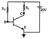
DifficultMCQ
For the given Common Emitter $(CE)$ transistor circuit,the base current is $I_B = 0.04 \text{ mA}$. If the current gain $\beta = 100$ and the collector-emitter voltage $V_{CE} = 12 \text{ V}$,find the value of the collector resistance $R_C$ in $\text{k}\Omega$.
A
$2$
B
$0.7$
C
$1.4$
D
$2.3$
Solution
(A) Given:
Base current $I_B = 0.04 \text{ mA} = 0.04 \times 10^{-3} \text{ A}$
Collector current gain $\beta = 100$
Supply voltage $V_{CC} = 20 \text{ V}$
Collector-emitter voltage $V_{CE} = 12 \text{ V}$
First,calculate the collector current $I_C$ using the relation:
$I_C = \beta \times I_B$
$I_C = 100 \times 0.04 \times 10^{-3} \text{ A} = 4 \times 10^{-3} \text{ A} = 4 \text{ mA}$
Now,apply Kirchhoff's Voltage Law to the collector circuit:
$V_{CC} = I_C R_C + V_{CE}$
$R_C = \frac{V_{CC} - V_{CE}}{I_C}$
$R_C = \frac{20 \text{ V} - 12 \text{ V}}{4 \times 10^{-3} \text{ A}}$
$R_C = \frac{8}{4 \times 10^{-3}} \Omega = 2 \times 10^3 \Omega = 2 \text{ k}\Omega$
Thus,the value of $R_C$ is $2 \text{ k}\Omega$.
0 likes
View Solution107
MediumMCQ
When a transistor is used as a $CB$ transistor amplifier,the current gain is $0.8$. If the change in base current is $6 \ mA$,then the change in collector current is ....... $mA$.
A
$6$
B
$4.8$
C
$24$
D
$8$
Solution
(C) Given,the current gain for $CB$ configuration is $\alpha = 0.8$.
The current gain for $CE$ configuration is given by $\beta = \frac{\alpha}{1 - \alpha}$.
Substituting the value of $\alpha$: $\beta = \frac{0.8}{1 - 0.8} = \frac{0.8}{0.2} = 4$.
We know that $\beta = \frac{\Delta I_C}{\Delta I_B}$,where $\Delta I_C$ is the change in collector current and $\Delta I_B$ is the change in base current.
Given $\Delta I_B = 6 \ mA$.
Therefore,$\Delta I_C = \beta \times \Delta I_B = 4 \times 6 \ mA = 24 \ mA$.
0 likes
View Solution108
MediumMCQ
$A$ transistor is connected in a common base circuit with $\beta = 75$. For an emitter current of $5 \text{ mA}$,the value of the collector current is ........ $\text{mA}$.
A
$1.03$
B
$6.21$
C
$2.4$
D
$4.93$
Solution
(D) Given: $\beta = 75$,$I_e = 5 \text{ mA}$.
We know the relationship between current gain $\beta$ and $\alpha$ is given by $\beta = \frac{\alpha}{1 - \alpha}$.
Substituting the value of $\beta$: $75 = \frac{\alpha}{1 - \alpha} \implies 75(1 - \alpha) = \alpha \implies 75 - 75\alpha = \alpha$.
Solving for $\alpha$: $76\alpha = 75 \implies \alpha = \frac{75}{76}$.
Since $\alpha = \frac{I_c}{I_e}$,the collector current $I_c$ is given by $I_c = \alpha I_e$.
Substituting the values: $I_c = \left(\frac{75}{76}\right) \times 5 \text{ mA} \approx 4.93 \text{ mA}$.
0 likes
View Solution109
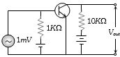
DifficultMCQ
For a common emitter transistor amplifier, the current gain is $\beta = 100$. Given the input voltage $V_{in} = 1 \text{ mV}$, input resistance $R_{in} = 1 \text{ k}\Omega$, and load resistance $R_L = 10 \text{ k}\Omega$, calculate the output voltage $V_{out}$ in $\text{V}$.
A
$100$
B
$0.1$
C
$1$
D
$10$
Solution
(C) The voltage gain $A_v$ of a common emitter amplifier is given by the product of current gain $\beta$ and resistance gain $\frac{R_L}{R_{in}}$.
$A_v = \beta \times \frac{R_L}{R_{in}}$
Given $\beta = 100$, $R_L = 10 \text{ k}\Omega$, and $R_{in} = 1 \text{ k}\Omega$.
$A_v = 100 \times \frac{10 \text{ k}\Omega}{1 \text{ k}\Omega} = 1000$.
The output voltage $V_{out}$ is given by $V_{out} = A_v \times V_{in}$.
Given $V_{in} = 1 \text{ mV} = 10^{-3} \text{ V}$.
$V_{out} = 1000 \times 10^{-3} \text{ V} = 1 \text{ V}$.
0 likes
View Solution110
DifficultMCQ
For a common emitter transistor,the current gain is $50$,the input resistance is $1 \ k\Omega$,and the input voltage is $0.01 \ V$. What is the collector current?
A
$100 \ \mu A$
B
$0.01 \ mA$
C
$0.25 \ mA$
D
$500 \ \mu A$
Solution
(D) Given:
Current gain $(\beta)$ = $50$
Input resistance $(R_i)$ = $1 \ k\Omega = 1000 \ \Omega$
Input voltage $(V_i)$ = $0.01 \ V$
First,calculate the base current $(i_b)$ using Ohm's law:
$i_b = \frac{V_i}{R_i} = \frac{0.01 \ V}{1000 \ \Omega} = 10^{-5} \ A$
Now,calculate the collector current $(i_c)$ using the current gain formula:
$i_c = \beta \times i_b$
$i_c = 50 \times 10^{-5} \ A$
$i_c = 5 \times 10^{-4} \ A = 500 \times 10^{-6} \ A = 500 \ \mu A$
0 likes
View Solution111
DifficultMCQ
For a common base transistor,the current gain is $\alpha = 0.98$. To produce a change of $2 \ mA$ in the emitter current,the change in the base current must be ......... $mA$.
A
$0.04$
B
$1.96$
C
$0.98$
D
$2$
Solution
(A) Given: Current gain $\alpha = 0.98$ and change in emitter current $\Delta i_e = 2 \ mA$.
We know that the collector current change is given by $\Delta i_c = \alpha \Delta i_e$.
Substituting the values: $\Delta i_c = 0.98 \times 2 = 1.96 \ mA$.
Using the relation for transistor currents,$\Delta i_e = \Delta i_b + \Delta i_c$,we can find the change in base current $\Delta i_b$.
$\Delta i_b = \Delta i_e - \Delta i_c = 2 \ mA - 1.96 \ mA = 0.04 \ mA$.
0 likes
View Solution112
MediumMCQ
What is the phase difference between the input and output voltage for a common-base amplifier?
A
$0$
B
$\pi /4$
C
$\pi /2$
D
$\pi$
Solution
(A) In a common-base $(CB)$ amplifier configuration,the input signal is applied between the emitter and base,and the output is taken between the collector and base.
Since the input current (emitter current) and output current (collector current) are in phase,the input voltage and output voltage are also in phase.
Therefore,the phase difference between the input and output voltage is $0$ radians.
Since the input current (emitter current) and output current (collector current) are in phase,the input voltage and output voltage are also in phase.
Therefore,the phase difference between the input and output voltage is $0$ radians.
0 likes
View Solution113
MediumMCQ
$A$ transistor is operated in common emitter configuration at a constant collector voltage $V_C = 1.5 \, V$ such that a change in the base current from $100 \, \mu A$ to $150 \, \mu A$ produces a change in the collector current from $5 \, mA$ to $10 \, mA$. The current gain $\beta$ is:
A
$50$
B
$67$
C
$75$
D
$100$
Solution
(D) The change in base current is $\Delta I_B = 150 \, \mu A - 100 \, \mu A = 50 \, \mu A = 50 \times 10^{-6} \, A$.
The change in collector current is $\Delta I_C = 10 \, mA - 5 \, mA = 5 \, mA = 5 \times 10^{-3} \, A$.
The current gain $\beta$ in common emitter configuration is defined as the ratio of the change in collector current to the change in base current:
$\beta = \frac{\Delta I_C}{\Delta I_B} = \frac{5 \times 10^{-3} \, A}{50 \times 10^{-6} \, A} = \frac{5000 \times 10^{-6}}{50 \times 10^{-6}} = 100$.
Therefore,the current gain $\beta$ is $100$.
0 likes
View Solution114
MediumMCQ
$A$ common emitter amplifier has a voltage gain of $50$,an input impedance of $100\; \Omega$,and an output impedance of $200\; \Omega$. The power gain of the amplifier is:
A
$1000$
B
$1250$
C
$100$
D
$5000$
Solution
(B) The voltage gain $(A_v)$ of an amplifier is given by the product of the current gain $(\beta)$ and the ratio of output impedance $(R_{\text{out}})$ to input impedance $(R_{\text{in}})$:
$A_v = \beta \times \frac{R_{\text{out}}}{R_{\text{in}}}$
Given $A_v = 50$,$R_{\text{in}} = 100\; \Omega$,and $R_{\text{out}} = 200\; \Omega$,we can find the current gain $(\beta)$:
$50 = \beta \times \frac{200}{100}$
$50 = \beta \times 2$
$\beta = 25$
The power gain $(A_p)$ is defined as the product of the current gain $(\beta)$ and the voltage gain $(A_v)$:
$A_p = \beta \times A_v$
$A_p = 25 \times 50 = 1250$
0 likes
View Solution115
MediumMCQ
For transistor action:
$(1)$ Base,emitter and collector regions should have similar size and doping concentrations.
$(2)$ The base region must be very thin and lightly doped.
$(3)$ The emitter-base junction is forward biased and base-collector junction is reverse biased.
$(4)$ Both the emitter-base junction as well as the base-collector junction are forward biased.
Which one of the following pairs of statements is correct?
A
$(4)$ and $(1)$
B
$(1)$ and $(2)$
C
$(2)$ and $(3)$
D
$(3)$ and $(4)$
Solution
(C) For effective transistor action,the following conditions must be met:
$1$. The base region must be very thin and lightly doped so that the majority of charge carriers from the emitter can pass through to the collector.
$2$. The emitter-base junction is forward biased to inject charge carriers into the base,and the base-collector junction is reverse biased to collect these carriers.
Therefore,statements $(2)$ and $(3)$ are correct.
0 likes
View Solution116
MediumMCQ
$A$ transistor is operated in common emitter configuration at $V_C = 2 \, V$ such that a change in the base current from $100 \, \mu A$ to $300 \, \mu A$ produces a change in the collector current from $10 \, mA$ to $20 \, mA$. The current gain is
A
$50$
B
$75$
C
$25$
D
$100$
Solution
(A) In a common emitter configuration,the current gain $\beta$ is defined as the ratio of the change in collector current to the change in base current.
$\beta = \frac{\Delta I_C}{\Delta I_B}$
Given:
Change in collector current,$\Delta I_C = 20 \, mA - 10 \, mA = 10 \, mA = 10 \times 10^{-3} \, A$
Change in base current,$\Delta I_B = 300 \, \mu A - 100 \, \mu A = 200 \, \mu A = 200 \times 10^{-6} \, A$
Substituting these values into the formula:
$\beta = \frac{10 \times 10^{-3}}{200 \times 10^{-6}}$
$\beta = \frac{10}{200} \times 10^3$
$\beta = \frac{1}{20} \times 1000 = 50$
Therefore,the current gain is $50$.
0 likes
View Solution117
MediumMCQ
In a $CE$ transistor amplifier,the audio signal voltage across the collector resistance of $2 \, k\Omega$ is $2 \, V$. If the base resistance is $1 \, k\Omega$ and the current amplification of the transistor is $100$,the input signal voltage is
A
$0.1 \, V$
B
$1 \, V$
C
$1 \, mV$
D
$10 \, mV$
Solution
(D) Given: Collector resistance $R_{C} = 2 \, k\Omega = 2 \times 10^{3} \, \Omega$.
Output voltage $V_{o} = 2 \, V$.
Base resistance $R_{B} = 1 \, k\Omega = 1 \times 10^{3} \, \Omega$.
Current amplification factor $\beta = 100$.
The output voltage is given by $V_{o} = I_{C} R_{C}$.
Therefore,the collector current is $I_{C} = \frac{V_{o}}{R_{C}} = \frac{2 \, V}{2 \times 10^{3} \, \Omega} = 10^{-3} \, A = 1 \, mA$.
Since $\beta = \frac{I_{C}}{I_{B}}$,the base current is $I_{B} = \frac{I_{C}}{\beta} = \frac{10^{-3} \, A}{100} = 10^{-5} \, A$.
The input signal voltage $V_{i}$ is given by $V_{i} = I_{B} R_{B}$.
Substituting the values: $V_{i} = (10^{-5} \, A) \times (1 \times 10^{3} \, \Omega) = 10^{-2} \, V = 10 \, mV$.
0 likes
View Solution118
MediumMCQ
The input resistance of a silicon transistor is $100\,\Omega$. Base current is changed by $40\,\mu A$,which results in a change in collector current by $2\,mA$. This transistor is used as a common emitter amplifier with a load resistance of $4\,k\Omega$. The voltage gain of the amplifier is:
A
$2000$
B
$3000$
C
$4000$
D
$1000$
Solution
(A) Given:
Input resistance,$R_{i} = 100\,\Omega$
Change in base current,$\Delta I_{B} = 40\,\mu A = 40 \times 10^{-6}\,A$
Change in collector current,$\Delta I_{C} = 2\,mA = 2 \times 10^{-3}\,A$
Load resistance,$R_{L} = 4\,k\Omega = 4000\,\Omega$
First,calculate the current gain $(\beta)$:
$\beta = \frac{\Delta I_{C}}{\Delta I_{B}} = \frac{2 \times 10^{-3}}{40 \times 10^{-6}} = \frac{2000}{40} = 50$
The voltage gain $(A_{V})$ of a common emitter amplifier is given by the formula:
$A_{V} = \beta \times \frac{R_{L}}{R_{i}}$
Substituting the values:
$A_{V} = 50 \times \frac{4000}{100}$
$A_{V} = 50 \times 40 = 2000$
Thus,the voltage gain of the amplifier is $2000$.
0 likes
View Solution119
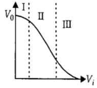
MediumMCQ
The transfer characteristics [output voltage $(V_o)$ vs input voltage $(V_i)$] for a base-biased transistor in $CE$ configuration are shown in the figure. For using a transistor as a switch,it is used:
A
in region $III$
B
both in region $I$ and $III$
C
in region $II$
D
in region $I$
Solution
(B) In the given graph:
Region $(I)$ represents the cutoff region,where the transistor is in the $OFF$ state.
Region $(II)$ represents the active region,where the transistor acts as an amplifier.
Region $(III)$ represents the saturation region,where the transistor is in the $ON$ state.
To use a transistor as a switch,it must be operated between the cutoff region ($OFF$ state) and the saturation region ($ON$ state).
Therefore,the transistor is used in both region $(I)$ and region $(III)$ for switching applications.
0 likes
View Solution120
MediumMCQ
To use a transistor as an amplifier,which of the following conditions must be satisfied?
A
no bias voltage is required
B
the emitter-base junction is forward-biased and the base-collector junction is reverse-biased
C
both junctions are forward-biased
D
both junctions are reverse-biased
Solution
(B) For a transistor to operate as an amplifier,it must be in the active region.
In the active region,the emitter-base junction is forward-biased,which allows charge carriers to flow from the emitter into the base.
The base-collector junction is reverse-biased,which allows the collector to collect the majority of the charge carriers injected from the emitter.
Therefore,the correct condition is that the emitter-base junction is forward-biased and the base-collector junction is reverse-biased.
0 likes
View Solution121
DifficultMCQ
In a common emitter $(CE)$ amplifier having a voltage gain $G,$ the transistor used has transconductance $0.03\, mho$ and current gain $25.$ If the above transistor is replaced with another one with transconductance $0.02\, mho$ and current gain $20,$ the voltage gain will be
A
$1.5 G$
B
$\frac{1}{3} G$
C
$\frac{5}{4} G$
D
$\frac{2}{3} G$
Solution
(D) Voltage gain is given by the product of current gain and resistance gain.
$A_{v} = \beta \times \frac{R_{\text{out}}}{R_{\text{in}}}$
Since transconductance $g_{m} = \frac{\beta}{R_{\text{in}}}$,we can write $R_{\text{in}} = \frac{\beta}{g_{m}}$.
Substituting this into the voltage gain formula: $A_{v} = \beta \times \frac{R_{\text{out}}}{\beta / g_{m}} = g_{m} R_{\text{out}}$.
For the first transistor: $G = 0.03 \times R_{\text{out}}$ (Equation $i$).
For the second transistor: $G' = 0.02 \times R_{\text{out}}$ (Equation $ii$).
Dividing Equation $ii$ by Equation $i$: $\frac{G'}{G} = \frac{0.02}{0.03} = \frac{2}{3}$.
Therefore,the new voltage gain is $G' = \frac{2}{3} G$.
0 likes
View Solution122
MediumMCQ
The input signal given to a $CE$ amplifier having a voltage gain of $150$ is $V_{in} = 2 \cos(15t + \frac{\pi}{3}) \text{ V}$. The corresponding output signal will be:
A
$300 \cos(15t + \frac{4\pi}{3}) \text{ V}$
B
$300 \cos(15t + \frac{\pi}{3}) \text{ V}$
C
$300 \cos(15t + \frac{2\pi}{3}) \text{ V}$
D
$2 \cos(15t + \frac{5\pi}{6}) \text{ V}$
Solution
(A) Given, input signal $V_{i} = 2 \cos(15t + \frac{\pi}{3})$ and voltage gain $A_{v} = 150$.
The voltage gain is defined as $A_{v} = \frac{V_{o}}{V_{i}}$, so the output signal magnitude is $V_{o} = A_{v} \times V_{i}$.
A common emitter $(CE)$ amplifier introduces a phase shift of $\pi$ $(180^{\circ})$ between the input and output signals.
Therefore, the output signal is $V_{o} = 150 \times 2 \cos(15t + \frac{\pi}{3} + \pi)$.
Simplifying the phase, $\frac{\pi}{3} + \pi = \frac{4\pi}{3}$.
Thus, $V_{o} = 300 \cos(15t + \frac{4\pi}{3}) \text{ V}$.
0 likes
View Solution123
MediumMCQ
For a $CE$ transistor amplifier,the audio signal voltage across the collector resistance of $2 \, k\Omega$ is $4 \, V$. If the current amplification factor $(\beta)$ of the transistor is $100$ and the base resistance is $1 \, k\Omega$,then the input signal voltage is ....... $mV$.
A
$30$
B
$15$
C
$10$
D
$20$
Solution
(D) Given: Collector resistance $R_C = 2 \, k\Omega = 2000 \, \Omega$,Output voltage $V_0 = 4 \, V$,Current amplification factor $\beta = 100$,Base resistance $R_B = 1 \, k\Omega = 1000 \, \Omega$.
The voltage gain $A_v$ of a $CE$ amplifier is given by the formula: $A_v = \beta \times \frac{R_C}{R_B}$.
Substituting the values: $A_v = 100 \times \frac{2000}{1000} = 200$.
We know that voltage gain $A_v = \frac{V_0}{V_i}$,where $V_i$ is the input signal voltage.
Therefore,$V_i = \frac{V_0}{A_v} = \frac{4 \, V}{200} = 0.02 \, V$.
Converting to millivolts $(mV)$: $V_i = 0.02 \times 1000 \, mV = 20 \, mV$.
0 likes
View Solution124
MediumMCQ
$A$ $npn$ transistor is connected in common emitter configuration in a given amplifier. $A$ load resistance of $800 \,\,\Omega$ is connected in the collector circuit and the voltage drop across it is $0.8 \,\, V$. If the current amplification factor is $0.96$ and the input resistance of the circuit is $192 \,\,\Omega$,the voltage gain and the power gain of the amplifier will respectively be
A
$3.69, 3.84$
B
$4, 4$
C
$4, 3.69$
D
$4, 3.84$
Solution
(D) Given: Load resistance $R_L = 800 \,\,\Omega$,Input resistance $R_i = 192 \,\,\Omega$,Current amplification factor $\beta = 0.96$.
The voltage gain $(A_v)$ for a common emitter amplifier is given by the formula:
$A_v = \beta \times \frac{R_L}{R_i}$
Substituting the values:
$A_v = 0.96 \times \frac{800}{192} = 0.96 \times 4.166... = 4$.
The power gain $(A_p)$ is given by the product of current gain and voltage gain:
$A_p = \beta \times A_v$
Substituting the values:
$A_p = 0.96 \times 4 = 3.84$.
Thus,the voltage gain is $4$ and the power gain is $3.84$.
0 likes
View Solution125
MediumMCQ
In a common emitter transistor amplifier,the audio signal voltage across the collector is $3\,V$. The resistance of the collector is $3\,k\Omega$. If the current gain is $100$ and the base resistance is $2\,k\Omega$,what are the voltage and power gain of the amplifier?
A
$15$ and $200$
B
$150$ and $15000$
C
$20$ and $2000$
D
$200$ and $1000$
Solution
(B) Given: Collector voltage $V_C = 3\,V$,Collector resistance $R_C = 3\,k\Omega$,Base resistance $R_B = 2\,k\Omega$,and Current gain $\beta = 100$.
The voltage gain $(A_V)$ of a common emitter $(CE)$ amplifier is given by the formula:
$A_V = \beta \times \left(\frac{R_C}{R_B}\right)$
Substituting the values:
$A_V = 100 \times \left(\frac{3\,k\Omega}{2\,k\Omega}\right) = 100 \times 1.5 = 150$.
The power gain $(A_P)$ is given by the product of current gain and voltage gain:
$A_P = \beta \times A_V$
Substituting the values:
$A_P = 100 \times 150 = 15000$.
Thus,the voltage gain is $150$ and the power gain is $15000$.
0 likes
View Solution126
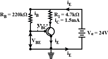
DifficultMCQ
$A$ common emitter amplifier circuit is shown in the figure. For the transistor used in the circuit,the current amplification factor is $\beta_{dc} = 100$. Other parameters are given in the figure.
A
$V_{BE} = +18.5 \text{ V}, V_{BC} = +2.85 \text{ V}$ and the amplifier is not working.
B
$V_{BE} = +20.7 \text{ V}, V_{BC} = +3.75 \text{ V}$ and the amplifier is not working.
C
$V_{BE} = +21.5 \text{ V}, V_{BC} = -2.75 \text{ V}$ and the amplifier is working.
D
$V_{BE} = +18.2 \text{ V}, V_{BC} = -3.45 \text{ V}$ and the amplifier is working.
Solution
(B) Given: $\beta_{dc} = 100$,$R_B = 220 \text{ k}\Omega$,$R_L = 4.7 \text{ k}\Omega$,$I_C = 1.5 \text{ mA}$,$V_{CC} = 24 \text{ V}$.
$1$. Calculate base current $I_B$:
$I_B = \frac{I_C}{\beta_{dc}} = \frac{1.5 \times 10^{-3} \text{ A}}{100} = 15 \times 10^{-6} \text{ A} = 15 \text{ } \mu\text{A}$.
$2$. Calculate $V_{BE}$ using Kirchhoff's voltage law in the base loop:
$V_{CC} = I_B R_B + V_{BE}$
$V_{BE} = V_{CC} - I_B R_B = 24 \text{ V} - (15 \times 10^{-6} \text{ A} \times 220 \times 10^3 \text{ } \Omega) = 24 \text{ V} - 3.3 \text{ V} = 20.7 \text{ V}$.
$3$. Calculate collector voltage $V_C$:
$V_C = V_{CC} - I_C R_L = 24 \text{ V} - (1.5 \times 10^{-3} \text{ A} \times 4.7 \times 10^3 \text{ } \Omega) = 24 \text{ V} - 7.05 \text{ V} = 16.95 \text{ V}$.
$4$. Calculate $V_{BC}$:
$V_{BC} = V_B - V_C = V_{BE} - V_C = 20.7 \text{ V} - 16.95 \text{ V} = 3.75 \text{ V}$.
$5$. Conclusion:
For an $NPN$ transistor to work as an amplifier,the base-emitter junction must be forward-biased $(V_{BE} > 0)$ and the base-collector junction must be reverse-biased $(V_{BC} < 0)$. Here,$V_{BC} = +3.75 \text{ V}$,which means the base-collector junction is forward-biased. Therefore,the transistor is in saturation and the amplifier is not working.
0 likes
View Solution127
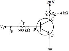
DifficultMCQ
In the circuit shown in the figure,the input voltage $V_i$ is $20\, V$,$V_{BE} = 0$,and $V_{CE} = 0$. The values of $I_B$,$I_C$,and $\beta$ are given by:
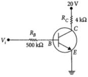
A
$I_B=40\,\mu A$,$I_C=10\,mA$,$\beta=250$
B
$I_B=25\,\mu A$,$I_C=5\,mA$,$\beta=200$
C
$I_B=40\,\mu A$,$I_C=5\,mA$,$\beta=125$
D
$I_B=20\,\mu A$,$I_C=5\,mA$,$\beta=250$
Solution
(C) Given: $V_{BE} = 0$,$V_{CE} = 0$,$V_i = 20\, V$,$R_B = 500\, k\Omega$,$R_C = 4\, k\Omega$.
For the output circuit (collector-emitter loop):
$V_{CC} = I_C R_C + V_{CE}$
Since $V_{CE} = 0$,we have:
$20\, V = I_C \times (4 \times 10^3\,\Omega) + 0$
$I_C = \frac{20}{4 \times 10^3} = 5 \times 10^{-3}\, A = 5\, mA$.
For the input circuit (base-emitter loop):
$V_i = I_B R_B + V_{BE}$
Since $V_{BE} = 0$,we have:
$20\, V = I_B \times (500 \times 10^3\,\Omega) + 0$
$I_B = \frac{20}{500 \times 10^3} = 40 \times 10^{-6}\, A = 40\,\mu A$.
The current gain $\beta$ is given by:
$\beta = \frac{I_C}{I_B} = \frac{5 \times 10^{-3}\, A}{40 \times 10^{-6}\, A} = \frac{5000}{40} = 125$.
0 likes
View Solution128
EasyMCQ
In a transistor,the forward bias is always kept smaller than the reverse bias. The correct reason is:
A
To avoid excessive heating of the transistor
B
To maintain a constant base current
C
To produce large voltage gain
D
None of these
Solution
(A) The correct option is $A$.
In a transistor,the emitter-base junction is forward-biased and the collector-base junction is reverse-biased.
If the forward bias is made too large,a very high number of majority charge carriers will be injected from the emitter into the base.
These carriers then move to the collector with high velocity.
This results in a high current flow,which leads to excessive heating of the transistor,potentially causing permanent damage to the device.
0 likes
View Solution129
EasyMCQ
In an $NPN$ transistor,if the doping in the base region is increased,then the collector current:
A
Increases
B
Decreases
C
Remains the same
D
None of these
Solution
(B) In an $NPN$ transistor,the base is $P$-type. Increasing the doping in the base region increases the number of holes available in the base.
This leads to a higher rate of recombination between the electrons (injected from the emitter) and the holes (in the base).
As a result,more electrons are lost in the base region,which increases the base current $(I_B)$.
Since the emitter current $(I_E)$ is constant,the increase in base current leads to a decrease in the collector current $(I_C)$,because $I_E = I_B + I_C$.
0 likes
View Solution130
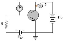
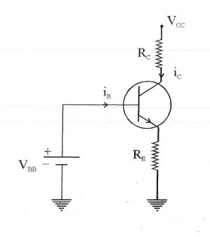
MediumMCQ
In the following circuit, a voltmeter $V$ is connected across a lamp $L$. What change would occur in the voltmeter reading if the resistance $R$ is reduced in value?
A
Increases
B
Decreases
C
Remains same
D
None of these
Solution
(A) In the given circuit, the emitter-base junction of the $N-P-N$ transistor is forward-biased by the battery $V_{BB}$ through the resistance $R$.
When the value of resistance $R$ is reduced, the base current $i_b$ increases according to Ohm's law $(i_b = (V_{BB} - V_{BE})/R)$.
Since the collector current $i_c$ is related to the base current by $i_c = \beta i_b$, an increase in $i_b$ leads to a significant increase in the collector current $i_c$.
The lamp $L$ is in the collector circuit. The potential difference across the lamp $L$ is given by $V_L = V_{CC} - i_c R_L$, where $R_L$ is the resistance of the lamp. However, in this specific common-emitter configuration, as $i_c$ increases, the voltage drop across the lamp $L$ increases because the transistor conducts more current from the $V_{CC}$ source through the lamp.
Therefore, the reading of the voltmeter $V$ connected across the lamp $L$ increases.
0 likes
View Solution131
EasyMCQ
In a common base mode of a transistor,the collector current is $5.488 \ mA$ for an emitter current of $5.60 \ mA$. The value of the base current amplification factor $(\beta)$ will be
A
$48$
B
$49$
C
$50$
D
$51$
Solution
(B) Given: Collector current $I_C = 5.488 \ mA$ and Emitter current $I_E = 5.60 \ mA$.
First,calculate the base current $I_B$ using the relation $I_B = I_E - I_C$.
$I_B = 5.60 \ mA - 5.488 \ mA = 0.112 \ mA$.
The base current amplification factor $\beta$ is defined as the ratio of collector current to base current: $\beta = \frac{I_C}{I_B}$.
Substituting the values: $\beta = \frac{5.488}{0.112} = 49$.
Thus,the value of $\beta$ is $49$.
0 likes
View Solution132
EasyMCQ
$A$ working transistor with its three legs marked $P, Q$ and $R$ is tested using a multimeter. No conduction is found between $P$ and $Q$. By connecting the common (negative) terminal of the multimeter to $R$ and the other (positive) terminal to $P$ or $Q$,some resistance is seen on the multimeter. Which of the following is true for the transistor?
A
It is an $npn$ transistor with $R$ as collector
B
It is an $npn$ transistor with $R$ as base
C
It is a $pnp$ transistor with $R$ as collector
D
It is a $pnp$ transistor with $R$ as emitter
Solution
(B) transistor consists of two $pn$ junctions.
$1$. No conduction between $P$ and $Q$ implies that $P$ and $Q$ are the collector and emitter terminals (or vice versa),as there is no direct $pn$ junction between them.
$2$. When the negative terminal of the multimeter is connected to $R$ and the positive terminal is connected to $P$ or $Q$,conduction (resistance) is observed.
$3$. In a multimeter,the common (negative) terminal is connected to the internal battery's negative pole,and the positive terminal is connected to the positive pole.
$4$. Conduction occurs when the $pn$ junction is forward-biased.
$5$. Since the negative terminal is at $R$ and the positive terminal is at $P$ or $Q$,$R$ must be the $p$-type material (base) and $P, Q$ must be $n$-type materials.
$6$. This configuration corresponds to an $npn$ transistor where $R$ is the base.
0 likes
View Solution133
MediumMCQ
For a common emitter configuration,if $\alpha$ and $\beta$ have their usual meanings,the incorrect relationship between $\alpha$ and $\beta$ is:
A
$\frac{1}{\alpha} = \frac{1}{\beta} - 1$
B
$\alpha = \frac{\beta^2}{1 + \beta^2}$
C
$\alpha = \frac{\beta}{1 - \beta}$
D
$\alpha = \frac{\beta}{1 + \beta}$
Solution
(C) We know that the current gain in common base configuration is $\alpha = \frac{I_C}{I_E}$ and in common emitter configuration is $\beta = \frac{I_C}{I_B}$.
Since $I_E = I_B + I_C$,we can write $\alpha = \frac{I_C}{I_B + I_C}$.
Dividing numerator and denominator by $I_B$,we get $\alpha = \frac{I_C/I_B}{1 + I_C/I_B} = \frac{\beta}{1 + \beta}$.
From this,we can derive $\frac{1}{\alpha} = \frac{1 + \beta}{\beta} = \frac{1}{\beta} + 1$,which implies $\frac{1}{\alpha} - \frac{1}{\beta} = 1$ or $\frac{1}{\alpha} = \frac{1}{\beta} + 1$.
Comparing the given options,option $C$ states $\alpha = \frac{\beta}{1 - \beta}$,which is incorrect because the correct relation is $\alpha = \frac{\beta}{1 + \beta}$.
0 likes
View Solution134
EasyMCQ
In a common emitter amplifier circuit using an $n-p-n$ transistor,the phase difference between the input and the output voltages will be.....$^o$
A
$45$
B
$90$
C
$135$
D
$180$
Solution
(D) In a common emitter configuration for an $n-p-n$ transistor,the input signal is applied to the base-emitter junction,and the output is taken from the collector-emitter junction.
When the input voltage increases,the base current increases,which in turn increases the collector current.
Due to the voltage drop across the load resistor $R_C$ connected to the collector,an increase in collector current leads to a decrease in the collector-emitter output voltage.
Therefore,the output voltage is $180^o$ out of phase with the input voltage.
0 likes
View Solution135
EasyMCQ
$A$ transistor is operating in the active mode. $v_1$ is the potential barrier across the base-emitter junction and $v_2$ is the potential barrier across the collector-base junction. $b_1$ is the width of the depletion layer of the base-emitter junction and $b_2$ is the width of the collector-base junction.
A
$v_1 > v_2, b_1 > b_2$
B
$v_1 < v_2, b_1 < b_2$
C
$v_1 > v_2, b_1 < b_2$
D
$v_1 < v_2, b_1 > b_2$
Solution
(B) In the active mode of a transistor,the base-emitter junction is forward-biased and the collector-base junction is reverse-biased.
Forward biasing reduces the potential barrier and the depletion layer width,while reverse biasing increases the potential barrier and the depletion layer width.
Since the base-emitter junction is forward-biased,its potential barrier $v_1$ is low and its depletion layer width $b_1$ is small.
Since the collector-base junction is reverse-biased,its potential barrier $v_2$ is high and its depletion layer width $b_2$ is large.
Therefore,$v_1 < v_2$ and $b_1 < b_2$.
0 likes
View Solution136
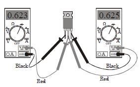
EasyMCQ
Identify the terminals of this $BJT$ and the type of $BJT$ $(NPN$ or $PNP)$. The multimeter is set to diode test mode (indicated by the symbol),and the black probe is connected to the $COM$ port while the red probe is connected to the $V\Omega$ port. Based on the connections shown in the image,determine the terminal configuration (from left to right) and the transistor type.
A
Emitter,Base,Collector,$NPN$
B
Emitter,Base,Collector,$PNP$
C
Collector,Base,Emitter,$NPN$
D
Collector,Base,Emitter,$PNP$
Solution
(A) $1$. In a $BJT$,the base terminal is common to both the emitter-base and collector-base junctions. When testing with a multimeter in diode mode,the base is the terminal that shows a forward voltage drop (typically $0.5 \ V$ to $0.8 \ V$) when connected to the red probe (positive) while the other two terminals are connected to the black probe (negative).
$2$. In the image,the center terminal is connected to both red probes. This indicates the center terminal is the Base.
$3$. Since the red probe (positive) is connected to the base and the black probe (negative) is connected to the other two terminals,the base is $P$-type. This identifies the transistor as an $NPN$ $BJT$.
$4$. The forward voltage drop from Base to Emitter is typically slightly higher than from Base to Collector. Here,the reading $0.625 \ V$ (left side) is slightly higher than $0.623 \ V$ (right side). Therefore,the left terminal is the Emitter and the right terminal is the Collector.
$5$. Thus,the configuration from left to right is Emitter,Base,Collector,and the type is $NPN$.
0 likes
View Solution137
MediumMCQ
In the transistor circuit shown,assume that the voltage drop between the base and the emitter is $0.5\ V$. What will be the ratio of the voltage across resistances $R_2$ and $R_1$ in order to make this circuit function as a source of constant current,$I = 1\ mA$?
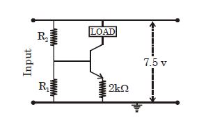
A
$4.5$
B
$3$
C
$2.5$
D
$2$
Solution
(D) The circuit is a constant current source where the emitter current $I_E \approx I_C = I = 1\ mA = 10^{-3}\ A$.
The voltage across the emitter resistor $R_E = 2\ k\Omega$ is $V_E = I_E \times R_E = 10^{-3}\ A \times 2 \times 10^3\ \Omega = 2\ V$.
The base-emitter voltage is $V_{BE} = 0.5\ V$.
Therefore,the base voltage is $V_B = V_E + V_{BE} = 2\ V + 0.5\ V = 2.5\ V$.
The total supply voltage is $V_{CC} = 7.5\ V$.
The voltage across $R_1$ is $V_{R_1} = V_B = 2.5\ V$.
The voltage across $R_2$ is $V_{R_2} = V_{CC} - V_B = 7.5\ V - 2.5\ V = 5\ V$.
The ratio of the voltage across $R_2$ to $R_1$ is $\frac{V_{R_2}}{V_{R_1}} = \frac{5\ V}{2.5\ V} = 2$.
0 likes
View Solution138
MediumMCQ
In a common base circuit of a transistor,the amplification factor is $0.95.$ The base current when the emitter current is $2\,mA,$ is ....$mA$
A
$0.1$
B
$0.2$
C
$0.19$
D
$1.9$
Solution
(A) Given the current amplification factor $\alpha = 0.95$ and the emitter current $I_{E} = 2\,mA$.
The collector current $I_{C}$ is given by the relation $I_{C} = \alpha \times I_{E}$.
Substituting the values,we get $I_{C} = 0.95 \times 2\,mA = 1.9\,mA$.
In a transistor,the emitter current is the sum of the collector current and the base current: $I_{E} = I_{C} + I_{B}$.
Therefore,the base current $I_{B} = I_{E} - I_{C}$.
Substituting the values,$I_{B} = 2\,mA - 1.9\,mA = 0.1\,mA$.
0 likes
View Solution139
MediumMCQ
In a common emitter transistor amplifier, an input signal of $10 \ mV$ is applied. Due to this signal, the change in base current is $50 \ \mu A$ and the corresponding change in collector current is $5 \ mA$. If the load resistance in the collector-emitter circuit is $5 \ k\Omega$, the change in output voltage will be ..... $V$.
A
$5$
B
$10$
C
$25$
D
$50$
Solution
(C) Given: Input signal voltage change $\Delta V_{in} = 10 \ mV = 10 \times 10^{-3} \ V$.
Change in base current $\Delta I_{B} = 50 \ \mu A = 50 \times 10^{-6} \ A$.
Change in collector current $\Delta I_{C} = 5 \ mA = 5 \times 10^{-3} \ A$.
Load resistance $R_{L} = 5 \ k\Omega = 5 \times 10^{3} \ \Omega$.
The change in output voltage $\Delta V_{out}$ is given by the product of the change in collector current and the load resistance:
$\Delta V_{out} = \Delta I_{C} \times R_{L}$
Substituting the values:
$\Delta V_{out} = (5 \times 10^{-3} \ A) \times (5 \times 10^{3} \ \Omega)$
$\Delta V_{out} = 25 \ V$.
Thus, the change in output voltage is $25 \ V$.
0 likes
View Solution140
MediumMCQ
The value of $I_c$ for the configuration shown is in $mA$.
A
$3.53$
B
$4.68$
C
$2.95$
D
$5.72$
Solution
(A) Given:
$V_{CC} = 12 \, V$
$R_B = 240 \, k\Omega$
$\beta = 75$
$V_{BE} = 0.7 \, V$
Step $1$: Calculate the base current $I_B$ using the input loop equation:
$I_B = \frac{V_{CC} - V_{BE}}{R_B} = \frac{12 \, V - 0.7 \, V}{240 \times 10^3 \, \Omega} = \frac{11.3 \, V}{240 \times 10^3 \, \Omega} = 47.08 \times 10^{-6} \, A = 47.08 \, \mu A$
Step $2$: Calculate the collector current $I_C$ using the relation $I_C = \beta I_B$:
$I_C = 75 \times 47.08 \, \mu A = 3531 \, \mu A = 3.53 \, mA$
Thus,the value of $I_C$ is $3.53 \, mA$.
0 likes
View Solution141
DifficultMCQ
In a common emitter transistor circuit,the base current is $40 \ \mu A$. Find the value of $V_{BE}$. (in $V$)
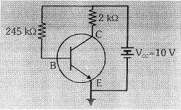
A
$2$
B
$0.2$
C
$0.8$
D
$0$
Solution
(B) From the given circuit diagram,the base-emitter loop consists of a voltage source $V_{CC} = 10 \ V$,a base resistor $R_B = 245 \ k\Omega$,and the base-emitter junction $V_{BE}$.
Applying Kirchhoff's Voltage Law $(KVL)$ to the base loop:
$V_{CC} - I_B R_B - V_{BE} = 0$
Given $I_B = 40 \ \mu A = 40 \times 10^{-6} \ A$ and $R_B = 245 \ k\Omega = 245 \times 10^3 \ \Omega$.
Substituting the values:
$10 - (40 \times 10^{-6} \times 245 \times 10^3) - V_{BE} = 0$
$10 - (40 \times 0.245) - V_{BE} = 0$
$10 - 9.8 - V_{BE} = 0$
$0.2 - V_{BE} = 0$
$V_{BE} = 0.2 \ V$.
0 likes
View Solution142
MediumMCQ
In an experiment,the input characteristics are shown for a $CE$ configuration $n-p-n$ transistor for different output voltages. Based on the graph,which of the following is correct?
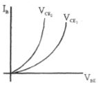
A
$V_{CE_1} > V_{CE_2}$
B
$V_{CE_1} = V_{CE_2}$
C
$V_{CE_1} < V_{CE_2}$
D
None of these
Solution
(A) In the input characteristics of a common-emitter $(CE)$ transistor,the base current $I_B$ is plotted against the base-emitter voltage $V_{BE}$ for a constant collector-emitter voltage $V_{CE}$.
As the collector-emitter voltage $V_{CE}$ increases,the depletion region width at the collector-base junction increases,which reduces the effective base width. This leads to a decrease in the recombination of charge carriers in the base region,causing the base current $I_B$ to decrease for a fixed $V_{BE}$.
Therefore,for a given $V_{BE}$,a higher $V_{CE}$ results in a lower $I_B$.
Looking at the graph,the curve for $V_{CE_2}$ is shifted to the left (higher $I_B$ for the same $V_{BE}$) compared to the curve for $V_{CE_1}$.
This implies that $V_{CE_2}$ must be smaller than $V_{CE_1}$,i.e.,$V_{CE_2} < V_{CE_1}$ or $V_{CE_1} > V_{CE_2}$.
0 likes
View Solution143
DifficultMCQ
For the given bipolar junction transistor,find the approximate value of $I_B$,if $V_{CC} = 9 \ V$,$V_{BB} = 1.5 \ V$,$R_C = 13 \ k\Omega$,$R_E = 17 \ k\Omega$,and $\beta = 100$. (Assume the transistor is in active mode and $V_{BE} = 0.7 \ V$)
A
$3 \times 10^{-4} \ mA$
B
$5 \times 10^{-4} \ mA$
C
$6 \times 10^{-4} \ mA$
D
$2 \times 10^{-4} \ mA$
Solution
(B) Applying Kirchhoff's voltage law to the base-emitter loop:
$V_{BB} = I_B R_B + V_{BE} + I_E R_E$
Since there is no base resistor $R_B$ in the circuit diagram,the equation simplifies to:
$V_{BB} = V_{BE} + I_E R_E$
Given $V_{BB} = 1.5 \ V$,$V_{BE} = 0.7 \ V$,and $R_E = 17 \ k\Omega = 17 \times 10^3 \ \Omega$:
$1.5 = 0.7 + I_E (17 \times 10^3)$
$0.8 = I_E (17 \times 10^3)$
$I_E = \frac{0.8}{17 \times 10^3} \ A = \frac{0.8}{17} \ mA \approx 0.047 \ mA = 47 \times 10^{-3} \ mA$
We know that $I_E = (\beta + 1) I_B$:
$I_B = \frac{I_E}{\beta + 1} = \frac{0.047 \ mA}{101} \approx 0.000465 \ mA = 4.65 \times 10^{-4} \ mA$
Rounding to the nearest provided option,we get $I_B \approx 5 \times 10^{-4} \ mA$.
0 likes
View Solution144
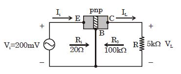
MediumMCQ
In the following transistor circuit,$R_i$ is the input resistance and $R_0$ is the output resistance. The approximate voltage gain for the circuit is:
A
$50$
B
$250$
C
$150$
D
$100$
Solution
(B) The input current $I_i$ is given by the ratio of input voltage $V_i$ to input resistance $R_i$:
$I_i = \frac{V_i}{R_i} = \frac{200 \text{ mV}}{20 \text{ } \Omega} = \frac{0.2 \text{ V}}{20 \text{ } \Omega} = 10 \text{ mA}$.
For a common-base transistor configuration,the collector current $I_C$ is approximately equal to the emitter current $I_E$ (i.e.,$I_C \approx I_E = I_i$):
$I_L \approx I_i = 10 \text{ mA}$.
The output load voltage $V_L$ across the load resistance $R = 5 \text{ k}\Omega$ is:
$V_L = I_L \times R = (10 \text{ mA}) \times (5 \text{ k}\Omega) = (10 \times 10^{-3} \text{ A}) \times (5 \times 10^3 \text{ } \Omega) = 50 \text{ V}$.
The voltage gain $A_V$ is defined as the ratio of output voltage $V_L$ to input voltage $V_i$:
$A_V = \frac{V_L}{V_i} = \frac{50 \text{ V}}{200 \text{ mV}} = \frac{50}{0.2} = 250$.
0 likes
View Solution145
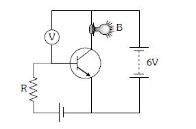
MediumMCQ
In the given circuit, a voltmeter $V$ is connected across a bulb $B$. If the value of the resistor $R$ is increased, what happens?
A
The voltmeter shows a lower voltage.
B
The voltmeter shows a higher voltage.
C
The voltmeter shows the same voltage.
D
The glow of the bulb will increase.
Solution
(A) In the given circuit, the transistor is in a common-emitter configuration. The input circuit (base-emitter) is forward-biased.
If the resistance $R$ in the input circuit is increased, the base current $I_{B}$ decreases according to Ohm's law $(I_{B} = \frac{V_{in} - V_{BE}}{R})$.
Since the collector current $I_{C}$ is related to the base current by the current gain $\beta$ $(I_{C} = \beta I_{B})$, a decrease in $I_{B}$ leads to a decrease in $I_{C}$.
The bulb $B$ is in the collector circuit. The voltage across the bulb is given by $V_{B} = V_{CC} - I_{C}R_{bulb}$.
As $I_{C}$ decreases, the voltage drop across the internal resistance of the transistor increases, and consequently, the voltage across the bulb $B$ decreases. Therefore, the voltmeter $V$ connected across the bulb will show a lower voltage.
0 likes
View Solution146
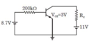
MediumMCQ
In the shown common emitter amplifier circuit,$\beta = 80$ and $V_{BE} = 0.7\,V$. The value of $R_C$ is:
A
$2.5\,\Omega$
B
$2.5\,k\Omega$
C
$1.5\,\Omega$
D
$1.5\,k\Omega$
Solution
(B) Applying Kirchhoff's Voltage Law $(KVL)$ to the input loop:
$8.7 - I_B(200 \times 10^3) - V_{BE} = 0$
$8.7 - I_B(200 \times 10^3) - 0.7 = 0$
$8 = I_B(200 \times 10^3)$
$I_B = \frac{8}{200 \times 10^3} = 4 \times 10^{-5}\,A = 40\,\mu A$
Given $\beta = 80$,we find the collector current $I_C$:
$I_C = \beta I_B = 80 \times 4 \times 10^{-5} = 320 \times 10^{-5} = 3.2 \times 10^{-3}\,A = 3.2\,mA$
Applying $KVL$ to the output loop:
$11 - I_C R_C - V_{CE} = 0$
$11 - (3.2 \times 10^{-3}) R_C - 3 = 0$
$8 = (3.2 \times 10^{-3}) R_C$
$R_C = \frac{8}{3.2 \times 10^{-3}} = 2.5 \times 10^3\,\Omega = 2.5\,k\Omega$
0 likes
View Solution147
DifficultMCQ
$A$ transistor is connected in common emitter $(CE)$ configuration. The collector supply is $8\ V$ and the voltage drop across a resistor of $800\,\Omega$ in the collector circuit is $0.5\ V$. If the current gain factor $\alpha$ is $0.96$,find the base current in $\mu A$.
A
$48$
B
$44$
C
$26$
D
$15$
Solution
(C) The current gain $\beta$ in common emitter configuration is related to $\alpha$ by the formula:
$\beta = \frac{\alpha}{1 - \alpha} = \frac{0.96}{1 - 0.96} = \frac{0.96}{0.04} = 24$.
The collector current $I_C$ is determined by the voltage drop across the collector resistor $R_C = 800\,\Omega$:
$I_C = \frac{V_{drop}}{R_C} = \frac{0.5\ V}{800\,\Omega} = 0.000625\ A = 0.625 \times 10^{-3}\ A$.
The base current $I_B$ is related to the collector current by $I_C = \beta I_B$,so:
$I_B = \frac{I_C}{\beta} = \frac{0.625 \times 10^{-3}\ A}{24} \approx 0.02604 \times 10^{-3}\ A$.
$I_B \approx 26 \times 10^{-6}\ A = 26\,\mu A$.
0 likes
View Solution148
DifficultMCQ
An $N-P-N$ transistor in a common emitter mode is used as a simple voltage amplifier with a collector current of $4 \ mA$. The terminal of an $8 \ V$ battery is connected to the collector through a load resistance $R_L$ and to the base through a resistance $R_B$. The collector-emitter voltage $V_{CE} = 4 \ V$,base-emitter voltage $V_{BE} = 0.6 \ V$ and base current amplification factor $\beta_{d.c.} = 100$. Calculate the values of $R_L$ and $R_B$.
A
$R_L = 1 \ k\Omega, R_B = 185 \ k\Omega$
B
$R_L = 2 \ k\Omega, R_B = 150 \ k\Omega$
C
$R_L = 1 \ k\Omega, R_B = 240 \ k\Omega$
D
$R_L = 3 \ k\Omega, R_B = 185 \ k\Omega$
Solution
(A) From the circuit diagram,the potential difference across the load resistance $R_L$ is given by:
$V_{R_L} = V_{CC} - V_{CE} = 8 \ V - 4 \ V = 4 \ V$
Using Ohm's law,$V_{R_L} = I_C R_L$,we have:
$R_L = \frac{V_{R_L}}{I_C} = \frac{4 \ V}{4 \times 10^{-3} \ A} = 10^3 \ \Omega = 1 \ k\Omega$
For the base circuit,the potential difference across the base resistance $R_B$ is:
$V_{R_B} = V_{CC} - V_{BE} = 8 \ V - 0.6 \ V = 7.4 \ V$
The base current $I_B$ is related to the collector current $I_C$ by the amplification factor $\beta$:
$I_B = \frac{I_C}{\beta} = \frac{4 \times 10^{-3} \ A}{100} = 4 \times 10^{-5} \ A$
Now,calculating $R_B$:
$R_B = \frac{V_{R_B}}{I_B} = \frac{7.4 \ V}{4 \times 10^{-5} \ A} = 1.85 \times 10^5 \ \Omega = 185 \ k\Omega$
Thus,$R_L = 1 \ k\Omega$ and $R_B = 185 \ k\Omega$.
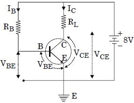
0 likes
View Solution149
MediumMCQ
In an $npn$ transistor,$10^{10}$ electrons enter the emitter in $10^{-8}$ second. If $1\%$ of electrons are lost in the base,the fraction of current that enters the collector and the current amplification factor are respectively:
A
$0.8$ and $49$
B
$0.9$ and $90$
C
$0.88$ and $88$
D
$0.99$ and $99$
Solution
(D) The emitter current $I_{E}$ is given by the rate of flow of charge: $I_{E} = \frac{n \cdot e}{t}$.
Given $n = 10^{10}$ electrons,$e = 1.6 \times 10^{-19} \ C$,and $t = 10^{-8} \ s$.
$I_{E} = \frac{10^{10} \times 1.6 \times 10^{-19}}{10^{-8}} = 1.6 \times 10^{-1} \ A = 0.16 \ A$.
Since $1\%$ of electrons are lost in the base,the base current $I_{B} = 0.01 \ I_{E}$.
The collector current $I_{C}$ is the remaining current: $I_{C} = I_{E} - I_{B} = I_{E} - 0.01 \ I_{E} = 0.99 \ I_{E}$.
The fraction of current entering the collector is $\frac{I_{C}}{I_{E}} = 0.99$.
The current amplification factor $\beta$ is defined as $\beta = \frac{I_{C}}{I_{B}} = \frac{0.99 \ I_{E}}{0.01 \ I_{E}} = 99$.
0 likes
View SolutionSemiconductor Electronics — Junction Transistor · Frequently Asked Questions
1Are these Semiconductor Electronics questions useful for JEE and NEET?
Yes. All questions in this section are mapped to JEE Main and NEET exam patterns. Previous year questions from JEE Main, NEET, GUJCET and state-level exams are included with full solutions.
2Can I switch to Hindi or Gujarati for these questions?
Yes. Use the language tabs in the hero section or the sidebar to view the same questions and solutions in English, Hindi or Gujarati.
3How do I generate a question paper from this subtopic?
Use the Vedclass Exam Paper Generator — select the chapter and subtopic, set difficulty, and generate Sets A, B, C, D automatically. First 3 chapters of every subject are free.
Vedclass Products
For Students
Vedclass Test Series
Mock tests in real JEE/NEET style with performance analysis. 5-day free trial.
Start Free TrialFor Teachers
Exam Paper Generator
Generate Set A/B/C/D papers from this chapter in 2 minutes. 3 chapters free.
Try FreeFor Institutes
Online Exam Module
Live online exams with unlimited students, 360° analytics & white-label branding.
See DemoFor Teachers & Institutes
Generate a Semiconductor Electronics Exam Paper in 2 Minutes
Select subtopic & difficulty — Sets A, B, C, D auto-generated with No Repeat logic.
First 3 chapters of every subject are free — no payment required.