
A English
Junction Transistor Questions in English
Class 12 Physics · Semiconductor Electronics · Junction Transistor
399+
Questions
English
Language
100%
With Solutions
Showing 48 of 399 questions in English
201
MediumMCQ
$Assertion$ : In common base configuration, the current gain of the transistor is less than unity.
$Reason$ : The collector terminal is reverse biased for amplification.
$Reason$ : The collector terminal is reverse biased for amplification.
A
If both Assertion and Reason are correct and the Reason is a correct explanation of the Assertion.
B
If both Assertion and Reason are correct but Reason is not a correct explanation of the Assertion.
C
If the Assertion is correct but Reason is incorrect.
D
If both the Assertion and Reason are incorrect.
Solution
(B) In a common base configuration, the input current is the emitter current $(I_e)$ and the output current is the collector current $(I_c)$.
The current gain $(\alpha)$ is defined as the ratio of the change in collector current to the change in emitter current: $\alpha = \frac{\Delta I_c}{\Delta I_e}$.
Since $I_e = I_c + I_b$ and the base current $(I_b)$ is always positive, $I_c < I_e$, which implies $\alpha < 1$.
Thus, the Assertion is correct.
The collector-base junction is indeed reverse-biased in a transistor to ensure that the majority of charge carriers injected from the emitter are collected at the collector, which is essential for amplification.
Thus, the Reason is also correct.
However, the fact that the collector is reverse-biased explains why the transistor works as an amplifier, but it is not the direct reason why the current gain is less than unity (which is due to the definition of the common base configuration where $I_c < I_e$).
Therefore, both are correct, but the Reason is not the correct explanation of the Assertion.
0 likes
View Solution202
MediumMCQ
Assertion: $A$ transistor amplifier in common emitter configuration has a low input impedance.
Reason: The base-to-emitter region is forward-biased.
Reason: The base-to-emitter region is forward-biased.
A
If both Assertion and Reason are correct and the Reason is a correct explanation of the Assertion.
B
If both Assertion and Reason are correct but Reason is not a correct explanation of the Assertion.
C
If the Assertion is correct but Reason is incorrect.
D
If both the Assertion and Reason are incorrect.
Solution
(A) The input impedance of a common emitter configuration is defined as $Z_{in} = \left| \frac{\Delta V_{BE}}{\Delta i_B} \right|_{V_{CE} = \text{constant}}$.
In a common emitter transistor, the base-emitter junction is forward-biased to allow current flow.
Because the base-emitter junction is forward-biased, the base current $\Delta i_B$ is relatively large for a small change in base-emitter voltage $\Delta V_{BE}$.
Since $Z_{in} = \frac{\Delta V_{BE}}{\Delta i_B}$, a small change in voltage divided by a relatively large change in current results in a low input impedance.
Therefore, both the Assertion and the Reason are correct, and the Reason is the correct explanation for the Assertion.
0 likes
View Solution203
EasyMCQ
What is the basic constitutional unit in the electronic circuit?
A
Resistor
B
Transistor
C
Capacitor
D
Inductor
Solution
(B) The transistor is considered the basic constitutional unit of modern electronic circuits. It acts as a fundamental building block for integrated circuits (ICs),microprocessors,and memory devices,functioning as either an electronic switch or an amplifier.
0 likes
View Solution204
Easy
In a $CE$ transistor amplifier,there is a current and voltage gain associated with the circuit. In other words,there is a power gain. Considering power as a measure of energy,does the circuit violate the law of conservation of energy?
Solution
(N/A) No,the law of conservation of energy is not violated. The increase in the energy of the output $AC$ signal is derived from the energy stored in the $DC$ power supply (battery).
When an amplifier is used,the $DC$ source provides the necessary energy to boost the weak input signal. Therefore,the energy of the output signal is equal to the energy of the input $AC$ signal plus the energy drawn from the $DC$ supply.
Thus,the law of conservation of energy is strictly maintained.
0 likes
View Solution205
Medium
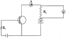
If the resistance $R_1$ is increased (see figure), how will the readings of the ammeter and voltmeter change?
Solution
(A-D) In the given common emitter transistor circuit, the input circuit consists of the base-emitter junction with resistance $R_1$.
When $R_1$ is increased, the base current $I_B$ decreases according to Ohm's law $(I_B = V_{in} / R_1)$.
The output collector current $I_C$ is related to the base current by the relation $I_C = \beta I_B$, where $\beta$ is the current gain of the transistor.
Since $I_B$ decreases, the collector current $I_C$ also decreases.
The ammeter is in series with the collector, so its reading decreases.
The voltmeter is connected across the resistor $R_2$ in the output circuit. The voltage across $R_2$ is given by $V_{out} = I_C R_2$.
As $I_C$ decreases, the voltage drop $V_{out}$ across $R_2$ decreases.
Therefore, the readings of both the ammeter and the voltmeter will decrease.
0 likes
View Solution206
Difficult
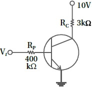
In the circuit shown in the figure,when the input voltage $V_i$ is $10\, V$,$V_{BE}$ is zero and $V_{CE}$ is also zero. Find the values of $I_B$,$I_C$,and $\beta$.
Solution
(D) In the input section:
$V_i = I_B R_B + V_{BE}$
Given $V_i = 10\, V$,$R_B = 400\, k\Omega = 400 \times 10^3\, \Omega$,and $V_{BE} = 0\, V$.
$10 = I_B (400 \times 10^3) + 0$
$I_B = \frac{10}{400 \times 10^3} = 0.025 \times 10^{-3}\, A = 25 \times 10^{-6}\, A = 25\, \mu A$
In the output section:
$V_{CC} = I_C R_C + V_{CE}$
Given $V_{CC} = 10\, V$,$R_C = 3\, k\Omega = 3 \times 10^3\, \Omega$,and $V_{CE} = 0\, V$.
$10 = I_C (3 \times 10^3) + 0$
$I_C = \frac{10}{3 \times 10^3} = 3.33 \times 10^{-3}\, A = 3.33\, mA = 3333\, \mu A$
Calculating current gain $\beta$:
$\beta = \frac{I_C}{I_B} = \frac{3.33 \times 10^{-3}}{25 \times 10^{-6}} = \frac{3333}{25} = 133.32$
0 likes
View Solution207
Difficult
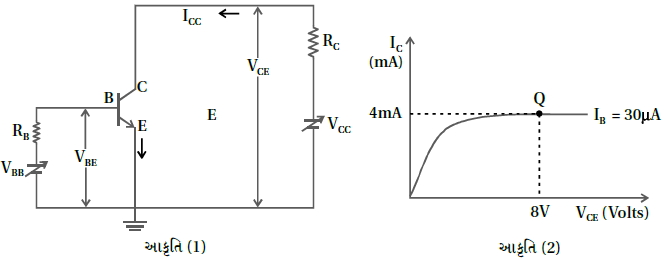
Consider the circuit arrangement shown in figure $(1)$ for studying input and output characteristics of an $n-p-n$ transistor in $CE$ configuration. Select the values of $R_B$ and $R_C$ for a transistor whose $V_{BE} = 0.7 \, V$, so that the transistor is operating at point $Q$ as shown in the characteristics shown in figure $(2)$. Given that the input impedance of the transistor is very small and $V_{CC} = V_{BB} = 16 \, V$, also find the voltage gain and power gain of the circuit making appropriate assumptions.
Solution
(N/A) From the graph in figure $(2)$, for the operating point $Q$, we have $I_B = 30 \, \mu A$, $I_C = 4 \, mA = 4 \times 10^{-3} \, A$, and $V_{CE} = 8 \, V$.
For the output circuit:
$V_{CC} = I_C R_C + V_{CE}$
$16 = (4 \times 10^{-3}) R_C + 8$
$R_C = \frac{8}{4 \times 10^{-3}} = 2 \times 10^3 \, \Omega = 2 \, k\Omega$.
For the input circuit:
$V_{BB} = I_B R_B + V_{BE}$
$16 = (30 \times 10^{-6}) R_B + 0.7$
$R_B = \frac{15.3}{30 \times 10^{-6}} = 0.51 \times 10^6 \, \Omega = 510 \, k\Omega$.
Voltage gain $A_V = \beta \frac{R_C}{R_{in}}$. Assuming input resistance $R_{in} \approx \frac{V_{BE}}{I_B} = \frac{0.7}{30 \times 10^{-6}} \approx 23.33 \, k\Omega$.
$A_V = \left( \frac{I_C}{I_B} \right) \left( \frac{R_C}{R_{in}} \right) = \left( \frac{4 \times 10^{-3}}{30 \times 10^{-6}} \right) \left( \frac{2000}{23333} \right) \approx 133.33 \times 0.0857 \approx 11.43$.
Power gain $A_P = A_V \times \beta = 11.43 \times 133.33 \approx 1524$.
0 likes
View Solution208
MediumMCQ
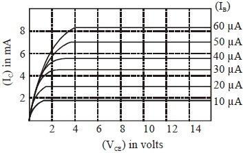
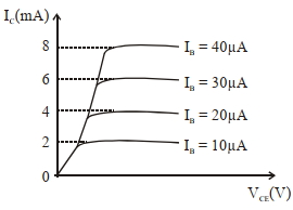
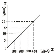
The output characteristics of a transistor are shown in the figure. When $V_{CE} = 10\, V$ and $I_{C} = 4.0\, mA$,then the value of $\beta_{ac}$ is:
A
$130$
B
$125$
C
$150$
D
$100$
Solution
(C) The $AC$ current gain $\beta_{ac}$ is defined as the ratio of the change in collector current $\Delta I_{C}$ to the change in base current $\Delta I_{B}$ at a constant collector-emitter voltage $V_{CE}$.
From the graph,at $V_{CE} = 10\, V$,the collector current $I_{C} = 4.0\, mA$ corresponds to a base current $I_{B} = 30\, \mu A$.
To find $\beta_{ac}$ around this operating point,we consider the adjacent curves for $I_{B} = 20\, \mu A$ and $I_{B} = 40\, \mu A$.
At $V_{CE} = 10\, V$:
For $I_{B} = 20\, \mu A$,$I_{C} = 3.0\, mA$.
For $I_{B} = 40\, \mu A$,$I_{C} = 6.0\, mA$.
Therefore,the change in base current is $\Delta I_{B} = 40\, \mu A - 20\, \mu A = 20\, \mu A = 20 \times 10^{-6}\, A$.
The change in collector current is $\Delta I_{C} = 6.0\, mA - 3.0\, mA = 3.0\, mA = 3.0 \times 10^{-3}\, A$.
The $AC$ current gain is $\beta_{ac} = \frac{\Delta I_{C}}{\Delta I_{B}} = \frac{3.0 \times 10^{-3}}{20 \times 10^{-6}} = \frac{3000}{20} = 150$.
0 likes
View Solution209
EasyMCQ
For transistor action,which of the following statements is correct?
A
The base region must be very thin and lightly doped.
B
Base,emitter and collector regions should have same doping concentrations.
C
Base,emitter and collector regions should have same size.
D
Both emitter junction as well as the collector junction are forward biased.
Solution
(A) For effective transistor action,the base region must be very thin and lightly doped to ensure that most of the charge carriers injected from the emitter reach the collector without recombining in the base.
0 likes
View Solution210
EasyMCQ
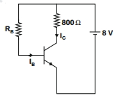
$A$ $N-P-N$ transistor is connected in common emitter configuration (see figure) in which the collector voltage drop across the load resistance $(800 \; \Omega)$ connected to the collector circuit is $0.8 \; V$. The collector current is .............. $mA$.
A
$0.2$
B
$2$
C
$0.1$
D
$1$
Solution
(D) The voltage drop across the load resistance $R_C$ is given by Ohm's law as:
$V_L = I_C \times R_C$
Given that the voltage drop $V_L = 0.8 \; V$ and the load resistance $R_C = 800 \; \Omega$.
Substituting these values into the equation:
$0.8 \; V = I_C \times 800 \; \Omega$
$I_C = \frac{0.8}{800} \; A$
$I_C = 0.001 \; A$
Since $1 \; A = 1000 \; mA$,we have:
$I_C = 0.001 \times 1000 \; mA = 1 \; mA$.
Therefore,the collector current is $1 \; mA$.
0 likes
View Solution211
DifficultMCQ
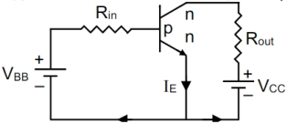
The given transistor operates in the saturation region. What should be the value of $V_{BB}$ (in $Volt$)?
$(R_{out} = 200 \, \Omega, R_{in} = 100 \, k\Omega, V_{CC} = 3 \, V, V_{BE} = 0.7 \, V, \beta = 200)$
$(R_{out} = 200 \, \Omega, R_{in} = 100 \, k\Omega, V_{CC} = 3 \, V, V_{BE} = 0.7 \, V, \beta = 200)$
A
$4.1$
B
$7.5$
C
$8.2$
D
$6.8$
Solution
(C) In the saturation region, the collector-emitter voltage $V_{CE}$ is approximately $0 \, V$.
From the output loop circuit:
$V_{CC} = I_C R_{out} + V_{CE}$
Since $V_{CE} = 0 \, V$ at saturation:
$3 = I_C (200)$
$I_C = \frac{3}{200} = 0.015 \, A = 15 \, mA$
Using the relation $\beta = \frac{I_C}{I_B}$, we find the base current $I_B$ required for saturation:
$I_B = \frac{I_C}{\beta} = \frac{15 \times 10^{-3}}{200} = 75 \times 10^{-6} \, A = 75 \, \mu A$
Now, applying Kirchhoff's Voltage Law $(KVL)$ to the input loop:
$V_{BB} = I_B R_{in} + V_{BE}$
$V_{BB} = (75 \times 10^{-6} \, A)(100 \times 10^3 \, \Omega) + 0.7 \, V$
$V_{BB} = 7.5 \, V + 0.7 \, V = 8.2 \, V$
Thus, the required value of $V_{BB}$ is $8.2 \, V$.
0 likes
View Solution212
MediumMCQ
What is the voltage gain in a common emitter amplifier,where input resistance is $3 \, \Omega$ and load resistance is $24 \, \Omega$,and the current gain $\beta = 0.6$?
A
$8.4$
B
$4.8$
C
$2.4$
D
$480$
Solution
(B) The voltage gain $A_v$ of a common emitter amplifier is defined as the ratio of the output voltage to the input voltage.
It is calculated using the formula:
$A_v = \beta \times \frac{R_L}{R_i}$
Given:
Input resistance $R_i = 3 \, \Omega$
Load resistance $R_L = 24 \, \Omega$
Current gain $\beta = 0.6$
Substituting the values into the formula:
$A_v = 0.6 \times \frac{24}{3}$
$A_v = 0.6 \times 8$
$A_v = 4.8$
Therefore,the voltage gain is $4.8$.
0 likes
View Solution213
MediumMCQ
An $npn$ transistor operates as a common emitter amplifier with a power gain of $10^{6}$. The input circuit resistance is $100\, \Omega$ and the output load resistance is $10\, k\Omega$. The common emitter current gain $\beta$ will be (Round off to the nearest integer).
A
$400$
B
$100$
C
$121$
D
$169$
Solution
(B) The power gain $(A_p)$ of a common emitter amplifier is given by the formula: $A_p = \beta^2 \times \frac{R_o}{R_i}$, where $\beta$ is the current gain, $R_o$ is the output resistance, and $R_i$ is the input resistance.
Given: $A_p = 10^6$, $R_i = 100\, \Omega$, and $R_o = 10\, k\Omega = 10^4\, \Omega$.
Substituting the values into the formula:
$10^6 = \beta^2 \times \frac{10^4}{10^2}$
$10^6 = \beta^2 \times 10^2$
$\beta^2 = \frac{10^6}{10^2} = 10^4$
$\beta = \sqrt{10^4} = 100$.
Thus, the common emitter current gain $\beta$ is $100$.
0 likes
View Solution214
MediumMCQ
The correct relation between $\alpha$ (ratio of collector current to emitter current) and $\beta$ (ratio of collector current to base current) of a transistor is :
A
$\beta=\frac{\alpha}{1+\alpha}$
B
$\alpha=\frac{\beta}{1-\alpha}$
C
$\beta=\frac{1}{1-\alpha}$
D
$\alpha=\frac{\beta}{1+\beta}$
Solution
(D) The current gain $\alpha$ is defined as the ratio of collector current $(I_{C})$ to emitter current $(I_{E})$: $\alpha = \frac{I_{C}}{I_{E}}$.
The current gain $\beta$ is defined as the ratio of collector current $(I_{C})$ to base current $(I_{B})$: $\beta = \frac{I_{C}}{I_{B}}$.
From Kirchhoff's current law for a transistor,the emitter current is the sum of base and collector currents: $I_{E} = I_{B} + I_{C}$.
Substituting $I_{E}$ in the expression for $\alpha$: $\alpha = \frac{I_{C}}{I_{B} + I_{C}}$.
Dividing the numerator and denominator by $I_{C}$: $\alpha = \frac{1}{\frac{I_{B}}{I_{C}} + 1}$.
Since $\frac{1}{\beta} = \frac{I_{B}}{I_{C}}$,we substitute this into the equation: $\alpha = \frac{1}{\frac{1}{\beta} + 1} = \frac{1}{\frac{1+\beta}{\beta}} = \frac{\beta}{1+\beta}$.
Therefore,the correct relation is $\alpha = \frac{\beta}{1+\beta}$.
0 likes
View Solution215
MediumMCQ
The typical output characteristics curve for a transistor working in the common-emitter configuration is shown in the figure. The estimated current gain from the figure is
A
$200$
B
$400$
C
$100$
D
$169$
Solution
(A) The current gain $\beta$ for a common-emitter configuration is defined as the ratio of the change in collector current $\Delta I_C$ to the change in base current $\Delta I_B$ at a constant collector-emitter voltage $V_{CE}$.
$\beta = \frac{\Delta I_C}{\Delta I_B}$
From the given graph,let us consider the change between two curves,for example,from $I_B = 10 \ \mu A$ to $I_B = 20 \ \mu A$ in the active region.
At $I_B = 10 \ \mu A$,the collector current $I_C = 2 \ mA = 2 \times 10^{-3} \ A$.
At $I_B = 20 \ \mu A$,the collector current $I_C = 4 \ mA = 4 \times 10^{-3} \ A$.
Therefore,$\Delta I_C = (4 - 2) \ mA = 2 \ mA = 2 \times 10^{-3} \ A$.
And $\Delta I_B = (20 - 10) \ \mu A = 10 \ \mu A = 10 \times 10^{-6} \ A$.
Now,calculating the current gain:
$\beta = \frac{2 \times 10^{-3}}{10 \times 10^{-6}} = \frac{2}{10} \times 10^3 = 0.2 \times 1000 = 200$.
Thus,the estimated current gain is $200$.
0 likes
View Solution216
MediumMCQ
If an emitter current is changed by $4\, mA$,the collector current changes by $3.5\, mA$. The value of $\beta$ will be
A
$7$
B
$0.5$
C
$0.875$
D
$3.5$
Solution
(A) The relationship between emitter current $(I_E)$,collector current $(I_C)$,and base current $(I_B)$ is given by $I_E = I_C + I_B$.
For small changes,this can be written as $\Delta I_E = \Delta I_C + \Delta I_B$.
Given $\Delta I_E = 4\, mA$ and $\Delta I_C = 3.5\, mA$,we find the change in base current:
$\Delta I_B = \Delta I_E - \Delta I_C = 4\, mA - 3.5\, mA = 0.5\, mA$.
The current gain $\beta$ is defined as the ratio of change in collector current to the change in base current:
$\beta = \frac{\Delta I_C}{\Delta I_B} = \frac{3.5\, mA}{0.5\, mA} = 7$.
Therefore,the value of $\beta$ is $7$.
0 likes
View Solution217
MediumMCQ
Given below are two statements:
Statement $I :$ $PN$ junction diodes can be used to function as a transistor,simply by connecting two diodes back-to-back,which acts as the base terminal.
Statement $II :$ In the study of transistors,the amplification factor $\beta$ indicates the ratio of the collector current to the base current.
In the light of the above statements,choose the correct answer from the options given below:
A
Statement $I$ is false but Statement $II$ is true
B
Both Statement $I$ and Statement $II$ are true
C
Both Statement $I$ and Statement $II$ are false
D
Statement $I$ is true but Statement $II$ is false
Solution
(A) Statement $I$ is false because a transistor is a single crystal device with specific doping profiles and regions (emitter,base,collector). Connecting two $PN$ junction diodes back-to-back does not create a functional transistor because it lacks the necessary charge carrier injection and control mechanisms inherent in a monolithic transistor structure.
Statement $II$ is true. The current amplification factor $\beta$ (or $h_{fe}$) for a common-emitter configuration is defined as the ratio of the collector current $(i_c)$ to the base current $(i_b)$,expressed as $\beta = \frac{i_c}{i_b}$.
Statement $II$ is true. The current amplification factor $\beta$ (or $h_{fe}$) for a common-emitter configuration is defined as the ratio of the collector current $(i_c)$ to the base current $(i_b)$,expressed as $\beta = \frac{i_c}{i_b}$.
0 likes
View Solution218
MediumMCQ
For a transistor in $CE$ mode to be used as an amplifier,it must be operated in:
A
Both cut-off and Saturation
B
Saturation region only
C
Cut-off region only
D
The active region only
Solution
(D) The active region of the $CE$ transistor is the linear region where the output current is directly proportional to the input current. This linearity makes it the best-suited region for operating the transistor as an amplifier.
0 likes
View Solution219
MediumMCQ
For a transistor,$\alpha$ and $\beta$ are given as $\alpha = \frac{I_{C}}{I_{E}}$ and $\beta = \frac{I_{C}}{I_{B}}$. Then the correct relation between $\alpha$ and $\beta$ is:
A
$\alpha = \frac{1-\beta}{\beta}$
B
$\beta = \frac{\alpha}{1-\alpha}$
C
$\alpha \beta = 1$
D
$\alpha = \frac{\beta}{1-\beta}$
Solution
(B) Given: $\alpha = \frac{I_{C}}{I_{E}}$ and $\beta = \frac{I_{C}}{I_{B}}$.
We know that the emitter current is the sum of collector current and base current: $I_{E} = I_{C} + I_{B}$.
Substituting $I_{E}$ in the expression for $\alpha$:
$\alpha = \frac{I_{C}}{I_{C} + I_{B}}$.
Dividing the numerator and denominator by $I_{B}$:
$\alpha = \frac{I_{C}/I_{B}}{(I_{C}/I_{B}) + (I_{B}/I_{B})} = \frac{\beta}{\beta + 1}$.
Now,rearrange to solve for $\beta$:
$\alpha(\beta + 1) = \beta$
$\alpha \beta + \alpha = \beta$
$\alpha = \beta - \alpha \beta$
$\alpha = \beta(1 - \alpha)$
$\beta = \frac{\alpha}{1 - \alpha}$.
0 likes
View Solution220
DifficultMCQ
$A$ transistor is connected in common emitter circuit configuration. The collector supply voltage is $10 \, V$ and the voltage drop across a resistor of $1000 \, \Omega$ in the collector circuit is $0.6 \, V$. If the current gain factor $(\beta)$ is $24$,then the base current is $.... \, \mu A$. (Round off to the Nearest Integer)
A
$5$
B
$10$
C
$25$
D
$30$
Solution
(C) Given:
Collector resistance $R_C = 1000 \, \Omega$
Voltage drop across collector resistor $\Delta V_C = 0.6 \, V$
Current gain $\beta = 24$
The collector current $I_C$ is given by Ohm's law:
$I_C = \frac{\Delta V_C}{R_C} = \frac{0.6 \, V}{1000 \, \Omega} = 0.6 \times 10^{-3} \, A = 6 \times 10^{-4} \, A$
The relationship between collector current $I_C$ and base current $I_B$ is:
$I_C = \beta \times I_B$
Therefore,the base current $I_B$ is:
$I_B = \frac{I_C}{\beta} = \frac{6 \times 10^{-4} \, A}{24} = 0.25 \times 10^{-4} \, A$
Converting to microamperes $(\mu A)$:
$I_B = 0.25 \times 10^{-4} \times 10^6 \, \mu A = 25 \, \mu A$.
0 likes
View Solution221
MediumMCQ
$A$ transistor is used in common-emitter mode in an amplifier circuit. When a signal of $10 \, mV$ is added to the base-emitter voltage, the base current changes by $10 \, \mu A$ and the collector current changes by $1.5 \, mA$. The load resistance is $5 \, k\Omega$. The voltage gain of the transistor will be
A
$950$
B
$750$
C
$780$
D
$790$
Solution
(B) The input resistance $r_i$ is calculated as the ratio of the change in base-emitter voltage to the change in base current:
$r_i = \frac{\Delta V_{BE}}{\Delta I_B} = \frac{10 \, mV}{10 \, \mu A} = \frac{10 \times 10^{-3} \, V}{10 \times 10^{-6} \, A} = 1000 \, \Omega = 1 \, k\Omega$.
The current gain $\beta$ is the ratio of the change in collector current to the change in base current:
$\beta = \frac{\Delta I_C}{\Delta I_B} = \frac{1.5 \, mA}{10 \, \mu A} = \frac{1.5 \times 10^{-3} \, A}{10 \times 10^{-6} \, A} = 150$.
The voltage gain $A_V$ for a common-emitter amplifier is given by the product of the current gain and the ratio of load resistance $R_L$ to input resistance $r_i$:
$A_V = \beta \times \frac{R_L}{r_i} = 150 \times \frac{5000 \, \Omega}{1000 \, \Omega} = 150 \times 5 = 750$.
0 likes
View Solution222
MediumMCQ
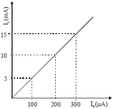
In an experiment of $CE$ configuration of $n-p-n$ transistor,the transfer characteristics are observed as given in the figure. If the input resistance is $200 \ \Omega$ and output resistance is $60 \ \Omega$,the voltage gain in this experiment will be:
A
$155$
B
$78$
C
$17$
D
$15$
Solution
(D) The voltage gain $A_v$ is given by the product of current gain $\beta$ and resistance gain.
$\beta = \frac{\Delta I_C}{\Delta I_B} = \frac{(15 - 5) \times 10^{-3} \text{ A}}{(300 - 100) \times 10^{-6} \text{ A}} = \frac{10 \times 10^{-3}}{200 \times 10^{-6}} = 50$.
The voltage gain $A_v = \beta \times \frac{R_o}{R_i} = 50 \times \frac{60 \ \Omega}{200 \ \Omega} = 50 \times 0.3 = 15$.
$\beta = \frac{\Delta I_C}{\Delta I_B} = \frac{(15 - 5) \times 10^{-3} \text{ A}}{(300 - 100) \times 10^{-6} \text{ A}} = \frac{10 \times 10^{-3}}{200 \times 10^{-6}} = 50$.
The voltage gain $A_v = \beta \times \frac{R_o}{R_i} = 50 \times \frac{60 \ \Omega}{200 \ \Omega} = 50 \times 0.3 = 15$.
0 likes
View Solution223
MediumMCQ
For a transistor to act as a switch,it must be operated in
A
Active region
B
Saturation state only
C
Cut-off state only
D
Saturation and cut-off state
Solution
(D) transistor acts as a switch by toggling between two states: the $Cut-off$ state and the $Saturation$ state.
In the $Cut-off$ state,the transistor is $OFF$ (no current flows).
In the $Saturation$ state,the transistor is $ON$ (maximum current flows).
Therefore,to function as a switch,it must be operated in both the $Saturation$ and $Cut-off$ states.
In the $Cut-off$ state,the transistor is $OFF$ (no current flows).
In the $Saturation$ state,the transistor is $ON$ (maximum current flows).
Therefore,to function as a switch,it must be operated in both the $Saturation$ and $Cut-off$ states.
0 likes
View Solution224
MediumMCQ
Given below are two statements: One is labelled as Assertion $A$ and the other is labelled as Reason $R$.
Assertion $A$: $n-p-n$ transistor permits more current than a $p-n-p$ transistor.
Reason $R$: Electrons have greater mobility as a charge carrier.
Choose the correct answer from the options given below:
Assertion $A$: $n-p-n$ transistor permits more current than a $p-n-p$ transistor.
Reason $R$: Electrons have greater mobility as a charge carrier.
Choose the correct answer from the options given below:
A
Both $A$ and $R$ are true and $R$ is the correct explanation of $A$.
B
Both $A$ and $R$ are true but $R$ is $NOT$ the correct explanation of $A$.
C
$A$ is true but $R$ is false.
D
$A$ is false but $R$ is true.
Solution
(A) In a transistor,the current is carried by charge carriers. In an $n-p-n$ transistor,the majority charge carriers are electrons,whereas in a $p-n-p$ transistor,the majority charge carriers are holes.
Electrons have higher mobility compared to holes because they are lighter and interact less with the crystal lattice.
Due to this higher mobility,electrons can move faster through the base region,allowing for higher current conduction in $n-p-n$ transistors compared to $p-n-p$ transistors.
Therefore,both Assertion $A$ and Reason $R$ are true,and $R$ is the correct explanation of $A$.
0 likes
View Solution225
MediumMCQ
$A$ transistor is used in an amplifier circuit in common emitter mode. If the base current changes by $100 \,\mu A$, it brings a change of $10 \,mA$ in collector current. If the load resistance is $2 \,k \Omega$ and input resistance is $1 \,k \Omega$, the value of power gain is $x \times 10^{4}$. The value of $x$ is . . . . . . .
A
$2$
B
$5$
C
$3$
D
$1$
Solution
(A) Given: Change in base current $\Delta i_{B} = 100 \,\mu A = 100 \times 10^{-6} \,A = 0.1 \,mA$.
Change in collector current $\Delta i_{C} = 10 \,mA$.
Load resistance $R_{L} = 2 \,k \Omega = 2000 \,\Omega$.
Input resistance $R_{in} = 1 \,k \Omega = 1000 \,\Omega$.
First, calculate the current gain $\beta$:
$\beta = \frac{\Delta i_{C}}{\Delta i_{B}} = \frac{10 \,mA}{0.1 \,mA} = 100$.
Power gain $A_{P}$ is given by the formula:
$A_{P} = \beta^{2} \times \frac{R_{L}}{R_{in}}$.
Substituting the values:
$A_{P} = (100)^{2} \times \frac{2000 \,\Omega}{1000 \,\Omega} = 10000 \times 2 = 20000$.
$A_{P} = 2 \times 10^{4}$.
Comparing this with $x \times 10^{4}$, we get $x = 2$.
0 likes
View Solution226
DifficultMCQ
The typical transfer characteristic of a transistor in $CE$ configuration is shown in the figure. $A$ load resistor of $2\,k\Omega$ is connected in the collector branch of the circuit used. The input resistance of the transistor is $0.50\,k\Omega$. The voltage gain of the transistor is:
A
$100$
B
$200$
C
$20$
D
$2000$
Solution
(B) The current gain $\beta$ in $CE$ configuration is given by $\beta = \frac{\Delta I_C}{\Delta I_B}$.
From the graph,we can choose two points to calculate the change in collector current $\Delta I_C$ and base current $\Delta I_B$.
Let us take the points $(I_B = 100\,\mu A, I_C = 5\,mA)$ and $(I_B = 200\,\mu A, I_C = 10\,mA)$.
$\Delta I_C = (10 - 5)\,mA = 5\,mA = 5 \times 10^{-3}\,A$.
$\Delta I_B = (200 - 100)\,\mu A = 100\,\mu A = 100 \times 10^{-6}\,A$.
Therefore,$\beta = \frac{5 \times 10^{-3}}{100 \times 10^{-6}} = \frac{5000}{100} = 50$.
The voltage gain $A_V$ is given by $A_V = \beta \times \frac{R_C}{R_{in}}$.
Given $R_C = 2\,k\Omega$ and $R_{in} = 0.50\,k\Omega$.
$A_V = 50 \times \frac{2\,k\Omega}{0.50\,k\Omega} = 50 \times 4 = 200$.
0 likes
View Solution227
MediumMCQ
For a constant collector-emitter voltage of $8\,V$,the collector current of a transistor changed from $4\,mA$ to $6\,mA$,whereas the base current changed from $20\,\mu A$ to $25\,\mu A$. If the transistor is in the active state,the small signal current gain (current amplification factor) will be:
A
$240$
B
$400$
C
$0.0025$
D
$200$
Solution
(B) The small signal current gain (current amplification factor) $\beta_{ac}$ is defined as the ratio of the change in collector current to the change in base current at a constant collector-emitter voltage $(V_{CE})$.
Given:
Change in collector current,$\Delta I_C = 6\,mA - 4\,mA = 2\,mA = 2 \times 10^{-3}\,A$
Change in base current,$\Delta I_B = 25\,\mu A - 20\,\mu A = 5\,\mu A = 5 \times 10^{-6}\,A$
The formula for current gain is:
$\beta_{ac} = \frac{\Delta I_C}{\Delta I_B}$
Substituting the values:
$\beta_{ac} = \frac{2 \times 10^{-3}}{5 \times 10^{-6}}$
$\beta_{ac} = \frac{2}{5} \times 10^3$
$\beta_{ac} = 0.4 \times 1000 = 400$
Thus,the current amplification factor is $400$.
0 likes
View Solution228
MediumMCQ
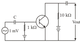
An $n-p-n$ transistor with current gain $\beta=100$ in common emitter configuration is shown in the figure. The output voltage of the amplifier will be $.....V$.
A
$0.1$
B
$1.0$
C
$10$
D
$100$
Solution
(B) The voltage gain $A_v$ of a common emitter amplifier is given by the formula:
$A_v = \frac{v_{\text{out}}}{v_{\text{in}}} = \beta \frac{R_{\text{out}}}{R_{\text{in}}}$
Given:
$\beta = 100$
$R_{\text{in}} = 1 \text{ k}\Omega = 10^3 \, \Omega$
$R_{\text{out}} = 10 \text{ k}\Omega = 10^4 \, \Omega$
$v_{\text{in}} = 1 \text{ mV} = 10^{-3} \, \text{V}$
Substituting the values:
$v_{\text{out}} = v_{\text{in}} \times \beta \times \frac{R_{\text{out}}}{R_{\text{in}}}$
$v_{\text{out}} = 10^{-3} \times 100 \times \frac{10 \times 10^3}{1 \times 10^3}$
$v_{\text{out}} = 10^{-3} \times 100 \times 10$
$v_{\text{out}} = 1 \, \text{V}$
0 likes
View Solution229
EasyMCQ
In which of the configurations of a transistor, the power gain is highest?
A
Common base
B
Common emitter
C
Common collector
D
Same in all the three
Solution
(B) The power gain of a transistor is defined as the product of current gain and voltage gain.
In a Common Emitter $(CE)$ configuration, both the current gain $(\beta)$ and the voltage gain are significantly high.
In a Common Base $(CB)$ configuration, the current gain $(\alpha)$ is less than $1$, resulting in low power gain.
In a Common Collector $(CC)$ configuration, the voltage gain is less than $1$, resulting in lower power gain compared to the $CE$ configuration.
Therefore, the power gain is highest in the Common Emitter configuration.
0 likes
View Solution230
EasyMCQ
In a transistor,the base is very lightly doped as compared to the emitter because by doing so:
A
The flow across the base region is mainly because of electrons
B
The flow across the base region is mainly because of holes
C
Recombination is decreased in the base region
D
Base current is high
Solution
(C) In a transistor,the base is made very thin and lightly doped to ensure that the majority of charge carriers injected from the emitter into the base pass through to the collector.
If the base were heavily doped,the number of majority charge carriers in the base would be high.
This would lead to a higher rate of recombination between the injected charge carriers from the emitter and the majority charge carriers in the base.
By keeping the base lightly doped,the recombination rate is significantly decreased,which allows most of the charge carriers to reach the collector,thereby increasing the current gain of the transistor.
0 likes
View Solution231
EasyMCQ
$A$ transistor is operated in $CE$ configuration at $V_{CC} = 2 \ V$ such that a change in base current from $100 \ \mu A$ to $200 \ \mu A$ produces a change in the collector current from $9 \ mA$ to $16.5 \ mA$. The value of current gain,$\beta$ is .........
A
$45$
B
$50$
C
$60$
D
$75$
Solution
(D) The current gain $\beta$ in a common emitter $(CE)$ configuration is defined as the ratio of the change in collector current $(\Delta I_C)$ to the change in base current $(\Delta I_B)$.
Given:
Change in base current,$\Delta I_B = 200 \ \mu A - 100 \ \mu A = 100 \ \mu A = 100 \times 10^{-6} \ A$.
Change in collector current,$\Delta I_C = 16.5 \ mA - 9 \ mA = 7.5 \ mA = 7.5 \times 10^{-3} \ A$.
Using the formula:
$\beta = \frac{\Delta I_C}{\Delta I_B}$
Substituting the values:
$\beta = \frac{7.5 \times 10^{-3} \ A}{100 \times 10^{-6} \ A}$
$\beta = \frac{7.5 \times 10^{-3}}{10^{-4}}$
$\beta = 7.5 \times 10^{1} = 75$.
Therefore,the value of current gain $\beta$ is $75$.
0 likes
View Solution232
EasyMCQ
Input signal to a common emitter amplifier having a voltage gain of $1000$ is given by $v_i = (0.004 \, V) \sin(\omega t + \pi/2)$. The corresponding output signal is
A
$(40 \, V) \sin(\omega t + \pi/2)$
B
$(0.004 \, V) \cos(\omega t + \pi/2)$
C
$(4 \, V) \cos(\omega t - \pi/2)$
D
$(4 \, V) \sin(\omega t - \pi/2)$
Solution
(D) The voltage gain $A_v$ of a common emitter amplifier is given as $1000$.
In a common emitter amplifier,there is a phase shift of $\pi$ radians $(180^{\circ})$ between the input and output signals.
The input signal is $v_i = (0.004 \, V) \sin(\omega t + \pi/2)$.
The output signal amplitude $V_0$ is given by $V_0 = A_v \times V_i = 1000 \times 0.004 \, V = 4 \, V$.
Due to the phase shift of $\pi$,the output signal is $v_o = 4 \sin(\omega t + \pi/2 + \pi) = 4 \sin(\omega t + 3\pi/2)$.
Since $\sin(\theta + 3\pi/2) = -\cos(\theta) = \sin(\theta - \pi/2)$,the output signal is $v_o = 4 \sin(\omega t - \pi/2) \, V$.
0 likes
View Solution233
EasyMCQ
In a common base transistor circuit,the current gain is $0.98$. On changing emitter current by $5.00 \,mA$,the change in collector current is ......... $mA$.
A
$0.196$
B
$2.45$
C
$4.9$
D
$5.1$
Solution
(C) In a common base $(CB)$ configuration,the current gain $\alpha$ is defined as the ratio of the change in collector current $(\Delta I_C)$ to the change in emitter current $(\Delta I_E)$.
$\alpha = \frac{\Delta I_C}{\Delta I_E}$
Given:
$\alpha = 0.98$
$\Delta I_E = 5.00 \,mA$
To find the change in collector current $(\Delta I_C)$:
$\Delta I_C = \alpha \times \Delta I_E$
$\Delta I_C = 0.98 \times 5.00 \,mA$
$\Delta I_C = 4.90 \,mA$
Therefore,the change in collector current is $4.9 \,mA$.
0 likes
View Solution234
EasyMCQ
For a transistor amplifier,the power gain and voltage gain are $7.5$ and $2.5$ respectively. The value of the current gain will be:
A
$0.33$
B
$0.66$
C
$0.99$
D
$3$
Solution
(D) The power gain $(A_p)$ of an amplifier is defined as the product of voltage gain $(A_v)$ and current gain $(A_i)$.
Mathematically,$A_p = A_v \times A_i$.
Given:
Power gain $(A_p)$ = $7.5$
Voltage gain $(A_v)$ = $2.5$
Substituting the values into the formula:
$7.5 = 2.5 \times A_i$
$A_i = \frac{7.5}{2.5} = 3$.
Therefore,the current gain is $3$.
Mathematically,$A_p = A_v \times A_i$.
Given:
Power gain $(A_p)$ = $7.5$
Voltage gain $(A_v)$ = $2.5$
Substituting the values into the formula:
$7.5 = 2.5 \times A_i$
$A_i = \frac{7.5}{2.5} = 3$.
Therefore,the current gain is $3$.
0 likes
View Solution235
EasyMCQ
The input resistance of a common-emitter amplifier is $2 \, k\Omega$ and a.c. current gain is $20$. If the load resistor used is $5 \, k\Omega$,calculate the transconductance of the transistor used in $\Omega^{-1}$.
A
$0.01$
B
$0.03$
C
$0.04$
D
$0.07$
Solution
(A) Given:
Input resistance $R_i = 2 \, k\Omega = 2 \times 10^3 \, \Omega$.
$A$.$C$. current gain $\beta = 20$.
Load resistance $R_L = 5 \, k\Omega$.
The transconductance $g_m$ of a transistor is defined as the ratio of the output current change to the input voltage change,which is given by the formula:
$g_m = \frac{\beta}{R_i}$
Substituting the given values:
$g_m = \frac{20}{2 \times 10^3 \, \Omega}$
$g_m = 10 \times 10^{-3} \, \Omega^{-1}$
$g_m = 0.01 \, \Omega^{-1}$
Thus,the transconductance is $0.01 \, \Omega^{-1}$.
0 likes
View Solution236
EasyMCQ
In a silicon transistor,a change of $7.89 \, mA$ in the emitter current produces a change of $7.8 \, mA$ in the collector current. What change in the base current is necessary to produce an equivalent change in the collector current (in $mA$)?
A
$9$
B
$0.9$
C
$0.09$
D
$0$
Solution
(C) The relationship between the emitter current $(\Delta I_E)$,collector current $(\Delta I_C)$,and base current $(\Delta I_B)$ in a transistor is given by the equation:
$\Delta I_E = \Delta I_C + \Delta I_B$
Given:
$\Delta I_E = 7.89 \, mA$
$\Delta I_C = 7.8 \, mA$
Substituting the values into the equation:
$7.89 \, mA = 7.8 \, mA + \Delta I_B$
$\Delta I_B = 7.89 \, mA - 7.8 \, mA$
$\Delta I_B = 0.09 \, mA$
Therefore,the change in base current required is $0.09 \, mA$.
0 likes
View Solution237
EasyMCQ
$A$ transistor has a current amplification factor of $60$. In a $CE$ amplifier, input resistance is $1 \, k\Omega$ and output voltage is $0.01 \, V$. The transconductance is (in $SI$ units)
A
$10^{-5}$
B
$6 \times 10^{-2}$
C
$6 \times 10^4$
D
$10$
Solution
(B) Given:
$Current \, amplification \, factor \, (\beta) = 60$
$Input \, resistance \, (R_i) = 1 \, k\Omega = 1000 \, \Omega$
The transconductance $(g_m)$ of a transistor is defined as the ratio of the current amplification factor to the input resistance:
$g_m = \frac{\beta}{R_i}$
Substituting the given values:
$g_m = \frac{60}{1000} \, \Omega^{-1}$
$g_m = 0.06 \, S = 6 \times 10^{-2} \, S$
Thus, the transconductance is $6 \times 10^{-2} \, SI \, units$.
0 likes
View Solution238
EasyMCQ
$A$ common emitter transistor amplifier has a current gain of $50$. If the load resistance is $9 \, k\Omega$ and the input resistance is $500 \, \Omega$,the voltage gain of the amplifier will be:
A
$900$
B
$300$
C
$200$
D
$100$
Solution
(A) The voltage gain $(A_v)$ of a common emitter transistor amplifier is given by the formula:
$A_v = \beta \times \frac{R_L}{R_i}$
Where $\beta$ is the current gain,$R_L$ is the load resistance,and $R_i$ is the input resistance.
Given:
$\beta = 50$
$R_L = 9 \, k\Omega = 9000 \, \Omega$
$R_i = 500 \, \Omega$
Substituting the values into the formula:
$A_v = 50 \times \frac{9000}{500}$
$A_v = 50 \times 18$
$A_v = 900$
Therefore,the voltage gain of the amplifier is $900$.
0 likes
View Solution239
EasyMCQ
$A$ transistor cannot be used as an
A
Amplifier
B
Oscillator
C
Modulator
D
Rectifier
Solution
(D) The correct answer is $D$.
$A$ transistor is a three-terminal semiconductor device used for amplification and switching. It can be configured as an amplifier,an oscillator,or a modulator.
$A$ rectifier is a device that converts alternating current $(AC)$ to direct current $(DC)$. Rectification is typically performed using $P-N$ junction diodes,not transistors. Therefore,a transistor cannot be used as a rectifier.
0 likes
View Solution240
EasyMCQ
What is the power gain in a $CE$ amplifier,where input resistance is $3 \, k\Omega$ and load resistance is $24 \, k\Omega$,given $\beta = 6$?
A
$180$
B
$288$
C
$240$
D
$480$
Solution
(B) The power gain $(A_p)$ of a common emitter $(CE)$ amplifier is given by the formula:
$A_p = \beta^2 \times \frac{R_L}{R_i}$
Where:
$\beta = 6$ (current gain)
$R_L = 24 \, k\Omega$ (load resistance)
$R_i = 3 \, k\Omega$ (input resistance)
Substituting the values into the formula:
$A_p = (6)^2 \times \left( \frac{24 \, k\Omega}{3 \, k\Omega} \right)$
$A_p = 36 \times 8$
$A_p = 288$
Thus,the power gain is $288$.
0 likes
View Solution241
EasyMCQ
$A$ transistor having $\alpha = 0.99$ is used in a common base amplifier. If the load resistance is $4.5 \, k\Omega$ and the dynamic resistance of the emitter junction is $50 \, \Omega$,the voltage gain of the amplifier will be:
A
$79.1$
B
$89.1$
C
$78.2$
D
$450$
Solution
(B) Given:
Common base current gain $\alpha = 0.99$
Load resistance $R_L = 4.5 \, k\Omega = 4500 \, \Omega$
Dynamic input resistance $R_i = 50 \, \Omega$
The voltage gain $A_v$ for a common base amplifier is given by the formula:
$A_v = \alpha \cdot \frac{R_L}{R_i}$
Substituting the given values:
$A_v = 0.99 \times \frac{4500}{50}$
$A_v = 0.99 \times 90$
$A_v = 89.1$
Thus,the voltage gain of the amplifier is $89.1$.
0 likes
View Solution242
MediumMCQ
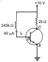
In the following transistor amplifier circuit,$\beta = 50$. The $V_{CE}$ of the transistor is .......... $V$.
A
$4$
B
$6$
C
$10$
D
$8$
Solution
(B) Given: $\beta = 50$,$I_B = 40 \, \mu A = 40 \times 10^{-6} \, A$,$V_{CC} = 10 \, V$,$R_C = 2 \, k\Omega = 2000 \, \Omega$.
Step $1$: Calculate the collector current $I_C$.
$I_C = \beta \times I_B = 50 \times 40 \times 10^{-6} \, A = 2000 \times 10^{-6} \, A = 2 \times 10^{-3} \, A = 2 \, mA$.
Step $2$: Apply Kirchhoff's Voltage Law to the output loop.
$V_{CE} = V_{CC} - I_C R_C$.
Step $3$: Substitute the values.
$V_{CE} = 10 \, V - (2 \times 10^{-3} \, A) \times (2000 \, \Omega) = 10 \, V - 4 \, V = 6 \, V$.
Therefore,the collector-emitter voltage $V_{CE}$ is $6 \, V$.
0 likes
View Solution243
EasyMCQ
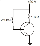
The given transistor amplifier connection is
A
Common base connection
B
Common emitter connection
C
Common collector connection
D
All of these
Solution
(B) In the given circuit diagram,the emitter terminal of the transistor is directly connected to the ground.
Since the emitter terminal is common to both the input (base-emitter) and output (collector-emitter) circuits,this configuration is known as the common emitter configuration.
Since the emitter terminal is common to both the input (base-emitter) and output (collector-emitter) circuits,this configuration is known as the common emitter configuration.
0 likes
View Solution244
EasyMCQ
Three amplifiers,each having a voltage gain of $10$,are connected in series. The resultant gain would be
A
$10$
B
$30$
C
$1000$
D
$10/3$
Solution
(C) When amplifiers are connected in series,the total voltage gain $(A_v)$ is the product of the individual voltage gains of each amplifier.
Given that there are $3$ amplifiers,each with a voltage gain of $A_1 = 10$,$A_2 = 10$,and $A_3 = 10$.
The resultant gain $A_{total} = A_1 \times A_2 \times A_3$.
$A_{total} = 10 \times 10 \times 10 = 1000$.
Therefore,the resultant gain is $1000$.
Given that there are $3$ amplifiers,each with a voltage gain of $A_1 = 10$,$A_2 = 10$,and $A_3 = 10$.
The resultant gain $A_{total} = A_1 \times A_2 \times A_3$.
$A_{total} = 10 \times 10 \times 10 = 1000$.
Therefore,the resultant gain is $1000$.
0 likes
View Solution245
EasyMCQ
In a transistor $(\beta=50)$,the voltage across $5 \, k\Omega$ load resistance in the collector circuit is $5 \, V$. The base current is ......... $mA$.
A
$0.02$
B
$0.03$
C
$0.08$
D
$0.09$
Solution
(A) Given: Current gain $\beta = 50$,Load resistance $R_C = 5 \, k\Omega = 5000 \, \Omega$,Voltage across load $V_C = 5 \, V$.
First,calculate the collector current $I_C$ using Ohm's law:
$I_C = \frac{V_C}{R_C} = \frac{5 \, V}{5000 \, \Omega} = 1 \times 10^{-3} \, A = 1 \, mA$.
Now,use the relation for current gain $\beta$ to find the base current $I_B$:
$\beta = \frac{I_C}{I_B} \implies I_B = \frac{I_C}{\beta}$.
Substituting the values:
$I_B = \frac{1 \, mA}{50} = 0.02 \, mA$.
Therefore,the base current is $0.02 \, mA$.
0 likes
View Solution246
MediumMCQ
For a $CE$ transistor amplifier,the audio signal voltage across the collector resistance of $2.0\,k\Omega$ is $2.0\,V$. Suppose the current amplification factor of the transistor is $100$. What should be the value of $R_B$ (in $k\Omega$) in series with $V_{BB}$ supply of $2.0\,V$ if the $dc$ base current has to be $10$ times the signal current?
A
$14$
B
$18$
C
$10$
D
$5$
Solution
(A) The output $ac$ voltage is $V_{out} = 2.0\,V$. The collector resistance is $R_C = 2.0\,k\Omega = 2000\,\Omega$.
The $ac$ collector current is $i_C = V_{out} / R_C = 2.0\,V / 2000\,\Omega = 1.0\,mA$.
The signal base current is $i_B = i_C / \beta = 1.0\,mA / 100 = 0.010\,mA$.
The $dc$ base current $I_B$ is given as $10$ times the signal current: $I_B = 10 \times 0.010\,mA = 0.10\,mA$.
Using the base circuit equation $V_{BB} = I_B R_B + V_{BE}$,we assume the standard base-emitter voltage $V_{BE} = 0.6\,V$.
$R_B = (V_{BB} - V_{BE}) / I_B = (2.0\,V - 0.6\,V) / 0.10\,mA = 1.4\,V / 0.10\,mA = 14\,k\Omega$.
0 likes
View Solution247
EasyMCQ
In a common emitter amplifier,the current gain is $62$. The collector resistance and input resistance are $5\,k\Omega$ and $500\,\Omega$ respectively. If the input voltage is $0.01\,V$,the output voltage is $..........\,V$.
A
$0.62$
B
$6.2$
C
$62$
D
$620$
Solution
(B) Given:
Current gain $(\beta)$ = $62$
Collector resistance $(R_C)$ = $5\,k\Omega = 5000\,\Omega$
Input resistance $(R_{in})$ = $500\,\Omega$
Input voltage $(V_{in})$ = $0.01\,V$
The voltage gain $(A_v)$ of a common emitter amplifier is given by:
$A_v = \beta \times \frac{R_C}{R_{in}}$
$A_v = 62 \times \frac{5000}{500} = 62 \times 10 = 620$
The output voltage $(V_o)$ is given by:
$V_o = A_v \times V_{in}$
$V_o = 620 \times 0.01\,V = 6.2\,V$
Therefore,the output voltage is $6.2\,V$.
0 likes
View Solution248
EasyMCQ
$A$ transistor connected in common emitter mode has a load resistance of $5 \, k\Omega$. If the input peak voltage is $5 \, mV$ and the current gain $(\beta)$ is $50$, find the voltage gain.
A
$250$
B
$500$
C
$125$
D
$50$
Solution
(A) The voltage gain $(A_v)$ of a common emitter transistor amplifier is given by the formula: $A_v = \beta \times \frac{R_L}{R_{in}}$, where $\beta$ is the current gain, $R_L$ is the load resistance, and $R_{in}$ is the input resistance.
Given: $\beta = 50$, $R_L = 5 \, k\Omega = 5000 \, \Omega$, and input peak voltage $V_{in} = 5 \, mV = 0.005 \, V$.
Assuming the input resistance $R_{in}$ is $1 \, k\Omega$ (as implied by the ratio in the provided context), the voltage gain is calculated as:
$A_v = 50 \times \frac{5 \, k\Omega}{1 \, k\Omega} = 50 \times 5 = 250$.
0 likes
View SolutionSemiconductor Electronics — Junction Transistor · Frequently Asked Questions
1Are these Semiconductor Electronics questions useful for JEE and NEET?
Yes. All questions in this section are mapped to JEE Main and NEET exam patterns. Previous year questions from JEE Main, NEET, GUJCET and state-level exams are included with full solutions.
2Can I switch to Hindi or Gujarati for these questions?
Yes. Use the language tabs in the hero section or the sidebar to view the same questions and solutions in English, Hindi or Gujarati.
3How do I generate a question paper from this subtopic?
Use the Vedclass Exam Paper Generator — select the chapter and subtopic, set difficulty, and generate Sets A, B, C, D automatically. First 3 chapters of every subject are free.
Vedclass Products
For Students
Vedclass Test Series
Mock tests in real JEE/NEET style with performance analysis. 5-day free trial.
Start Free TrialFor Teachers
Exam Paper Generator
Generate Set A/B/C/D papers from this chapter in 2 minutes. 3 chapters free.
Try FreeFor Institutes
Online Exam Module
Live online exams with unlimited students, 360° analytics & white-label branding.
See DemoFor Teachers & Institutes
Generate a Semiconductor Electronics Exam Paper in 2 Minutes
Select subtopic & difficulty — Sets A, B, C, D auto-generated with No Repeat logic.
First 3 chapters of every subject are free — no payment required.