
A English
Application of junction diode (Rectifier) Questions in English
Class 12 Physics · Semiconductor Electronics · Application of junction diode (Rectifier)
129+
Questions
English
Language
100%
With Solutions
Showing 49 of 129 questions in English
51
MediumMCQ
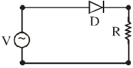
$A$ $p-n$ junction diode $(D)$ shown in the figure can act as a rectifier. An alternating current source $(V)$ is connected in the circuit. The current $(I)$ in the resistor $(R)$ can be shown by:
A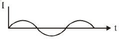
B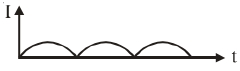
C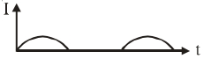
D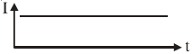
Solution
(C) single $p-n$ junction diode connected in series with an alternating current $(A.C.)$ source and a load resistor $(R)$ acts as a half-wave rectifier.
During the positive half-cycle of the input $A.C.$,the diode is forward-biased and conducts current through the resistor $(R)$.
During the negative half-cycle of the input $A.C.$,the diode is reverse-biased and does not conduct,resulting in zero current through the resistor $(R)$.
Therefore,the output current waveform consists of only the positive half-cycles,with gaps where the negative half-cycles would have been. This corresponds to the graph shown in option $C$.
0 likes
View Solution52
DifficultMCQ
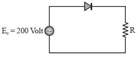
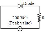
$A$ sinusoidal voltage of peak value $200 \ V$ is connected to a diode and resistor $R$ in the circuit shown so that half-wave rectification occurs. If the forward resistance of the diode is negligible compared to $R$,the rms voltage (in volt) across $R$ is approximately:
A
$200$
B
$100$
C
$\frac{200}{\sqrt{2}}$
D
$280$
Solution
(B) In a half-wave rectifier,the output voltage across the resistor $R$ exists only for the positive half-cycle of the input sinusoidal voltage.
The instantaneous voltage is given by $V(t) = V_0 \sin(\omega t)$,where $V_0 = 200 \ V$.
The root mean square (rms) voltage $V_{rms}$ is defined as:
$V_{rms} = \sqrt{\frac{1}{T} \int_{0}^{T} V^2(t) dt}$
For a half-wave rectified signal,the integration is over the interval $[0, T/2]$:
$V_{rms} = \sqrt{\frac{1}{T} \int_{0}^{T/2} (V_0 \sin(\omega t))^2 dt}$
Since $\omega = \frac{2\pi}{T}$,we have:
$V_{rms} = V_0 \sqrt{\frac{1}{T} \int_{0}^{T/2} \sin^2(\omega t) dt} = V_0 \sqrt{\frac{1}{T} \int_{0}^{T/2} \frac{1 - \cos(2\omega t)}{2} dt}$
$V_{rms} = V_0 \sqrt{\frac{1}{2T} [t - \frac{\sin(2\omega t)}{2\omega}]_{0}^{T/2}} = V_0 \sqrt{\frac{1}{2T} [\frac{T}{2} - 0]} = \frac{V_0}{2}$
Given $V_0 = 200 \ V$,the rms voltage is:
$V_{rms} = \frac{200}{2} = 100 \ V$.
0 likes
View Solution53
MediumMCQ
$A$ sinusoidal peak voltage of $15\ V$ is connected between the input terminals of the circuit shown in the figure. Assume the diodes are ideal. In the output waveform,
A
Positive peaks of input clipped at $+12\ V$ and negative peaks at $-6\ V$
B
Positive peaks of input dipped at $+6\ V$ and negative peaks at $-12\ V$
C
Positive peaks of input clipped at $+12\ V$ and negative peaks at $-12\ V$
D
Positive peaks of input clipped at $+6\ V$ and negative peaks at $-6\ V$
Solution
(A) For the positive half-cycle of the input voltage,diode $D_1$ becomes forward-biased when the input voltage exceeds $12\ V$. Thus,the output is clipped at $+12\ V$.
For the negative half-cycle of the input voltage,diode $D_2$ becomes forward-biased when the input voltage becomes more negative than $-6\ V$ (since the battery is connected with its positive terminal to the ground). Thus,the output is clipped at $-6\ V$.
Therefore,the positive peaks are clipped at $+12\ V$ and the negative peaks are clipped at $-6\ V$.
0 likes
View Solution54
DifficultMCQ
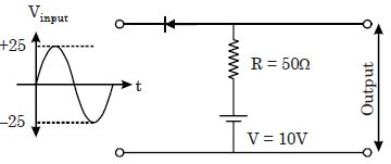
An ideal diode is connected in a circuit with resistance $R = 50\ \Omega$ and battery $V = 10\ V$ as shown in the figure. What are the maximum and minimum values of the output voltage when no load is applied?
A
$10\ V, -25\ V$
B
$10\ V, -15\ V$
C
$25\ V, -25\ V$
D
$25\ V, -15\ V$
Solution
(A) The input voltage $V_{\text{in}}$ varies sinusoidally between $+25\ V$ and $-25\ V$.
$1$. Positive half cycle $(V_{\text{in}} > 10\ V)$: The diode is forward-biased when $V_{\text{in}} > 10\ V$. Since the diode is ideal,it acts as a short circuit. The output voltage is clamped by the battery $V = 10\ V$. Thus,$V_{\text{out}} = 10\ V$.
$2$. Negative half cycle $(V_{\text{in}} < 10\ V)$: The diode is reverse-biased. It acts as an open circuit. No current flows through the resistor $R$,so there is no voltage drop across it. The output terminals are directly connected to the input source. Thus,$V_{\text{out}} = V_{\text{in}}$.
The maximum value of the output voltage is $10\ V$ (clamped).
The minimum value of the output voltage is the minimum input voltage,which is $-25\ V$.
Therefore,the maximum and minimum values are $10\ V$ and $-25\ V$ respectively.
0 likes
View Solution55
DifficultMCQ
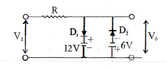
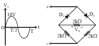
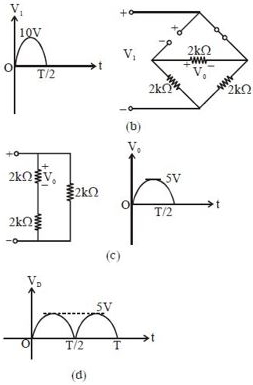
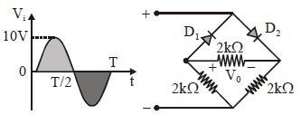
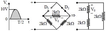
In the circuit shown in the figure, determine the output waveform and the output d.c. level of $V_0$.
A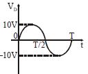
B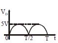
C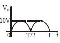
D
None of these
Solution
(C) For the positive half-cycle of the input, the resulting network is shown in figure $(b).$ Diode $D_1$ is in the "off" state and $D_2$ is in the "on" state.
The circuit can be simplified as a voltage divider consisting of two $2 \text{ k}\Omega$ resistors in series across the input voltage. It is clear that:
$V_0 = \frac{2 \text{ k}\Omega}{2 \text{ k}\Omega + 2 \text{ k}\Omega} V_i = \frac{1}{2} V_i$
Given the peak input voltage $V_{i \max} = 10 \text{ V}$, the peak output voltage is:
$V_{0 \max} = \frac{1}{2} (10 \text{ V}) = 5 \text{ V}$
During the negative half-cycle, the roles of diodes $D_1$ and $D_2$ are interchanged, and the output $V_0$ will appear as a full-wave rectified signal with a peak of $5 \text{ V}$, as shown in figure $(d).$
For full-wave rectification, the d.c. level is given by:
$V_{dc} = \frac{2 V_m}{\pi} = 0.636 V_m = 0.636 \times 5 \text{ V} = 3.18 \text{ V}$
0 likes
View Solution56
DifficultMCQ
$A$ half-wave rectifier is used to supply $100 \, V$ $dc$ to a load of $800 \, \Omega$. The diode resistance is $200 \, \Omega$. The $ac$ voltage required is :.......$V$
A
$392.5$
B
$280$
C
$\frac{392.5}{\sqrt{2}}$
D
$\frac{196.25}{\sqrt{2}}$
Solution
(A) For a half-wave rectifier, the $dc$ output voltage is given by $V_{dc} = I_{dc} \times R_L = \frac{I_0}{\pi} \times R_L$.
Since $I_0 = \frac{E_0}{r_f + R_L}$, we have $V_{dc} = \frac{E_0 \times R_L}{\pi(r_f + R_L)}$.
Given $V_{dc} = 100 \, V$, $R_L = 800 \, \Omega$, and $r_f = 200 \, \Omega$:
$100 = \frac{E_0 \times 800}{3.14(200 + 800)} = \frac{800 E_0}{3140}$.
Solving for the peak voltage $E_0$: $E_0 = \frac{100 \times 3140}{800} = 392.5 \, V$.
The $rms$ value of the $ac$ input voltage for a half-wave rectifier is $E_{rms} = \frac{E_0}{2} = \frac{392.5}{2} = 196.25 \, V$. However, standard textbook problems often ask for the peak voltage $E_0$ in this context. Based on the options provided, the peak voltage $E_0 = 392.5 \, V$ is the intended answer.
0 likes
View Solution57
EasyMCQ
Which of the following circuits provides full-wave rectification of an $A.C.$ input?
A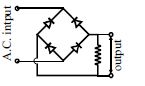
B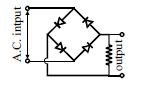
C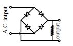
D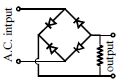
Solution
(B) full-wave bridge rectifier uses four diodes arranged in a bridge configuration to convert both halves of the $A.C.$ input cycle into a unidirectional output across the load resistor.
In the provided options,the circuit that correctly connects the $A.C.$ input to the bridge and the load resistor across the output terminals is shown in image $818-b639$.
In this configuration,during the positive half-cycle of the $A.C.$ input,two diodes conduct,and during the negative half-cycle,the other two diodes conduct,ensuring current flows through the load resistor in the same direction during both half-cycles.
0 likes
View Solution58
DifficultMCQ
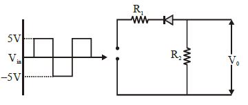
$A$ waveform shown is applied to the following circuit. Assuming an ideal diode configuration and $R_1 = R_2$, which of the following output waveforms will be produced?
A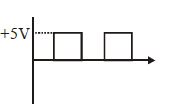
B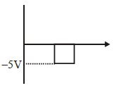
C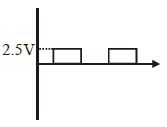
D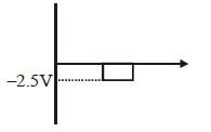
Solution
(D) The $P-N$ junction diode will conduct only when it is forward-biased. Looking at the circuit, the diode is oriented such that it conducts when the input voltage $V_{in}$ is negative (specifically $-5\,V$).
When $V_{in} = -5\,V$, the diode acts as a short circuit (ideal).
The circuit then becomes a voltage divider with two equal resistors $R_1$ and $R_2$ in series across the source voltage of $5\,V$ (magnitude).
The output voltage $V_0$ across $R_2$ is given by the voltage divider rule:
$V_0 = V_{in} \times \frac{R_2}{R_1 + R_2}$
Since $R_1 = R_2$, we have:
$V_0 = -5\,V \times \frac{R_2}{R_2 + R_2} = -5\,V \times \frac{R_2}{2R_2} = -5\,V \times 0.5 = -2.5\,V$.
Therefore, the output waveform will show a negative pulse of $-2.5\,V$ during the interval when the input is $-5\,V$.
0 likes
View Solution59
DifficultMCQ
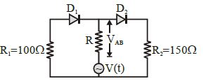
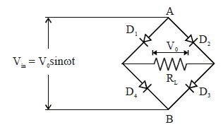
In the circuit given below, $V(t)$ is the sinusoidal voltage source. The voltage drop $V_{AB}(t)$ across the resistance $R$ is:
A
Is half wave rectified
B
Is full wave rectified
C
Has the same peak value in the positive and negative half cycles
D
Has different peak values during positive and negative half cycles
Solution
(D) In the positive half cycle of the input $V(t)$, diode $D_1$ is forward-biased and $D_2$ is reverse-biased. The current flows through the loop containing $R_1$ and $R$. The voltage drop across $R$ is determined by the voltage divider rule: $V_{AB, pos} = V(t) \cdot \frac{R}{R + R_1}$.
In the negative half cycle of the input $V(t)$, diode $D_2$ is forward-biased and $D_1$ is reverse-biased. The current flows through the loop containing $R_2$ and $R$. The voltage drop across $R$ is $V_{AB, neg} = V(t) \cdot \frac{R}{R + R_2}$.
Since the current direction through $R$ reverses in the two half cycles, the output is not rectified.
Because $R_1 = 100 \ \Omega$ and $R_2 = 150 \ \Omega$ are different, the peak values of the voltage drop $V_{AB}(t)$ during the positive and negative half cycles will be different.
0 likes
View Solution60
MediumMCQ
The frequency of the input $a.c.$ of a full-wave rectifier is $50\,Hz$. The frequency of the output is.....$Hz$.
A
$50$
B
$25$
C
$75$
D
$100$
Solution
(D) In a full-wave rectifier, the output signal completes two cycles for every one cycle of the input $a.c.$ signal.
Therefore, the frequency of the output wave is twice the frequency of the input wave.
Given, input frequency $f_{in} = 50\,Hz$.
Output frequency $f_{out} = 2 \times f_{in} = 2 \times 50\,Hz = 100\,Hz$.
Therefore, the frequency of the output wave is twice the frequency of the input wave.
Given, input frequency $f_{in} = 50\,Hz$.
Output frequency $f_{out} = 2 \times f_{in} = 2 \times 50\,Hz = 100\,Hz$.
0 likes
View Solution61
MediumMCQ
In the half-wave rectifier circuit shown,which of the following waveforms is true for $V_{CD}$,the output across $C$ and $D$?
A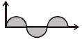
B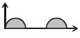
C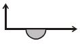
D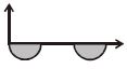
Solution
(B) half-wave rectifier consists of a diode in series with a load resistor.
During the positive half-cycle of the input $AC$ voltage,the diode is forward-biased and conducts current,allowing the positive half-cycle to appear across the load resistor $CD$.
During the negative half-cycle,the diode is reverse-biased and acts as an open circuit,resulting in zero voltage across the load resistor $CD$.
Therefore,the output waveform $V_{CD}$ consists of only the positive half-cycles,which corresponds to option $B$.
0 likes
View Solution62
MediumMCQ
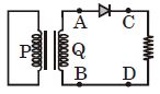
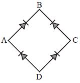
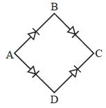
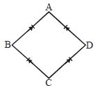
In the diagram,the input is across the terminals $A$ and $C$ and the output is across the terminals $B$ and $D$,then the output is
A
zero
B
Same as input
C
Full wave rectifier
D
Half wave rectifier
Solution
(C) The given circuit is a bridge rectifier configuration.
When an alternating voltage is applied across terminals $A$ and $C$,the diodes are arranged such that current flows through the load connected across $B$ and $D$ during both the positive and negative half-cycles of the input $AC$ signal.
Specifically,during the positive half-cycle,two diodes conduct,and during the negative half-cycle,the other two diodes conduct,ensuring that the current through the load remains in the same direction.
Therefore,this circuit acts as a full wave rectifier.
0 likes
View Solution63
MediumMCQ
The peak voltage in the output of a half-wave diode rectifier fed with a sinusoidal signal without a filter is $10 \, V$. The $dc$ component of the output voltage is
A
$\frac{10}{\sqrt{2}} \, V$
B
$\frac{10}{\pi} \, V$
C
$10 \, V$
D
$\frac{20}{\pi} \, V$
Solution
(B) For a half-wave rectifier,the output voltage is a series of half-sinusoidal pulses.
The average or $dc$ value of the output voltage is given by the formula $V_{dc} = \frac{V_0}{\pi}$,where $V_0$ is the peak voltage.
Given that the peak voltage $V_0 = 10 \, V$.
Substituting the value,we get $V_{dc} = \frac{10}{\pi} \, V$.
The average or $dc$ value of the output voltage is given by the formula $V_{dc} = \frac{V_0}{\pi}$,where $V_0$ is the peak voltage.
Given that the peak voltage $V_0 = 10 \, V$.
Substituting the value,we get $V_{dc} = \frac{10}{\pi} \, V$.
0 likes
View Solution64
DifficultMCQ
In the circuit shown in the figure, the maximum output voltage $V_0$ is.....$V$.
A
$0$
B
$5$
C
$10$
D
$\frac{5}{\sqrt{2}}$
Solution
(B) During the positive half cycle of the input voltage, diode $D_1$ is forward-biased and diode $D_2$ is reverse-biased.
The circuit simplifies to a voltage divider network consisting of three $2 \text{ k}\Omega$ resistors.
The input voltage $V_i$ is applied across a series combination of two $2 \text{ k}\Omega$ resistors, while the output voltage $V_0$ is taken across one of these $2 \text{ k}\Omega$ resistors.
Using the voltage divider rule:
$V_0 = V_i \times \frac{2 \text{ k}\Omega}{2 \text{ k}\Omega + 2 \text{ k}\Omega} = V_i \times \frac{2}{4} = \frac{V_i}{2}$.
Given the maximum input voltage $(V_i)_{\max} = 10 \text{ V}$, the maximum output voltage is:
$(V_0)_{\max} = \frac{(V_i)_{\max}}{2} = \frac{10 \text{ V}}{2} = 5 \text{ V}$.
0 likes
View Solution65
MediumMCQ
For the given circuit shown in the figure,to act as a full-wave rectifier: $a.c.$ input should be connected across .............. and .................,and the $d.c.$ output would appear across ............. and ..................
A
$A, C, B, D$
B
$B, D, A, C$
C
$A, B, C, D$
D
$C, A, D, B$
Solution
(B) In a bridge rectifier circuit,the $a.c.$ input is applied across the two opposite junctions that are not connected to the same diode terminals in a way that would block current. Looking at the diagram,the $a.c.$ input is connected across points $B$ and $D$.
During the positive half-cycle,diodes connected to $B$ and $D$ conduct such that current flows through the load connected across $A$ and $C$.
During the negative half-cycle,the other pair of diodes conducts,again maintaining the same direction of current through the load connected across $A$ and $C$.
Therefore,the $a.c.$ input is connected across $B$ and $D$,and the $d.c.$ output is taken across $A$ and $C$.
0 likes
View Solution66
MediumMCQ
Which of the following statements is correct for a diode in a rectifier circuit?
A
In a full-wave rectifier,both diodes work alternatively.
B
In a full-wave rectifier,both diodes work simultaneously.
C
The efficiency of a full-wave rectifier and a half-wave rectifier is the same.
D
$A$ full-wave rectifier is bidirectional.
Solution
(A) full-wave rectifier uses two diodes to convert both halves of the input $AC$ cycle into $DC$.
During the first half-cycle of the input $AC$,one diode is forward-biased and conducts,while the other is reverse-biased.
During the second half-cycle,the roles are reversed,and the second diode conducts while the first remains off.
Thus,both diodes work alternatively to rectify the complete cycle.
Therefore,the correct statement is that in a full-wave rectifier,both diodes work alternatively.
0 likes
View Solution67
MediumMCQ
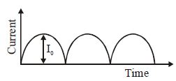
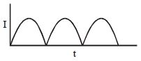
The output sinusoidal current versus time curve of a rectifier is shown in the figure. The average value of output current in this case is
A
$0$
B
$\frac{I_0}{2}$
C
$\frac{2I_0}{\pi}$
D
$I_0$
Solution
(C) The given figure represents a full-wave rectified output. The current varies as $I = I_0 \sin \omega t$ for the interval $0$ to $T/2$,where $T$ is the time period of the original $AC$ input. The time period of the rectified output is $T/2$.
The average value of the output current is given by:
$I_{av} = \frac{1}{T/2} \int_{0}^{T/2} I_0 \sin \omega t \, dt$
Substituting $\omega = \frac{2\pi}{T}$:
$I_{av} = \frac{2}{T} I_0 \int_{0}^{T/2} \sin \left( \frac{2\pi}{T} t \right) dt$
$I_{av} = \frac{2 I_0}{T} \left[ -\frac{\cos(\frac{2\pi}{T} t)}{\frac{2\pi}{T}} \right]_{0}^{T/2}$
$I_{av} = \frac{2 I_0}{T} \cdot \frac{T}{2\pi} \left[ -\cos(\pi) + \cos(0) \right]$
$I_{av} = \frac{I_0}{\pi} [ -(-1) + 1 ] = \frac{I_0}{\pi} [ 1 + 1 ] = \frac{2I_0}{\pi}$
0 likes
View Solution68
EasyMCQ
Which of the following circuits provides full wave rectification of an $ac$ input?
A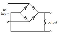
B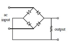
C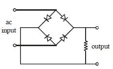
D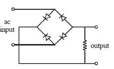
Solution
(A) full wave bridge rectifier uses four diodes arranged in a bridge configuration to ensure that current flows through the load resistor in the same direction during both the positive and negative half-cycles of the $ac$ input.
In a standard bridge rectifier,the diodes are oriented such that during the positive half-cycle,two diodes conduct,and during the negative half-cycle,the other two diodes conduct.
Analyzing the provided diagrams,the circuit that correctly connects the diodes to allow for this bidirectional current flow through the load is represented by the configuration where the diodes are oriented to form a closed loop with the $ac$ source and the load resistor,ensuring the output polarity remains constant.
Based on standard circuit diagrams for a bridge rectifier,the correct configuration is shown in option $A$.
0 likes
View Solution69
MediumMCQ
The output across the diode in the given circuit is:
A
Would be zero at all times.
B
Would be like a half wave rectifier with positive cycles in output.
C
Would be like a half wave rectifier with negative cycles in output.
D
Would be like that of a full wave rectifier.
Solution
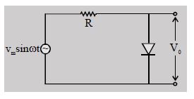
(C) In the given circuit, the diode is connected in parallel with the output terminals.
During the positive half cycle of the input $V_m \sin(\omega t)$, the diode is forward-biased. Since an ideal diode acts as a short circuit when forward-biased, the output voltage $V_0$ across the diode becomes $0 \ V$.
During the negative half cycle, the diode is reverse-biased. An ideal diode acts as an open circuit when reverse-biased. Therefore, the entire input voltage appears across the output terminals, i.e., $V_0 = V_m \sin(\omega t)$.
Thus, the output consists only of the negative half cycles of the input signal, which is characteristic of a half-wave rectifier with negative cycles in the output.
0 likes
View Solution70
MediumMCQ
The figure shows the current as a function of time at the output of a full-wave rectifier. The average value of this current is:
A
$\frac{I_0}{\sqrt{2}}$
B
$\frac{I_0}{2}$
C
$\frac{I_0}{\pi}$
D
$\frac{2I_0}{\pi}$
Solution
(D) In a full-wave rectifier,the output current consists of a series of half-sinusoidal pulses.
To find the average current $(I_{avg})$,we integrate the current over one complete cycle (from $t=0$ to $t=T/2$) and divide by the time interval $(T/2)$.
The current is given by $I = I_0 \sin(\omega t)$.
$I_{avg} = \frac{1}{T/2} \int_{0}^{T/2} I_0 \sin(\omega t) dt$
$I_{avg} = \frac{2}{T} \cdot I_0 \left[ -\frac{\cos(\omega t)}{\omega} \right]_{0}^{T/2}$
Since $\omega = \frac{2\pi}{T}$,we have $\omega \cdot \frac{T}{2} = \pi$.
$I_{avg} = \frac{2 I_0}{T \omega} [-\cos(\pi) + \cos(0)] = \frac{2 I_0}{T (2\pi/T)} [1 + 1] = \frac{2 I_0}{2\pi} \cdot 2 = \frac{2 I_0}{\pi}$.
0 likes
View Solution71
MediumMCQ
$A$ bridge rectifier is shown in the figure. Alternating input is given across $A$ and $C$. If the output is taken across $BD$,then it is
A
zero
B
same as input
C
half wave rectified
D
full wave rectified
Solution
(D) bridge rectifier circuit uses four diodes arranged in a bridge configuration to convert alternating current $(AC)$ into direct current $(DC)$.
In the given circuit,the input is applied across terminals $A$ and $C$.
During the positive half-cycle of the input,current flows through the diodes such that terminal $B$ becomes positive and terminal $D$ becomes negative.
During the negative half-cycle of the input,the current path changes,but due to the arrangement of the diodes,terminal $B$ remains positive and terminal $D$ remains negative relative to each other.
Since the output is taken across terminals $B$ and $D$,the current through the load resistor connected between $B$ and $D$ flows in the same direction for both the positive and negative half-cycles of the input.
Therefore,the output across $BD$ is a full-wave rectified signal.
0 likes
View Solution72
MediumMCQ
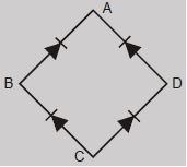
For the circuit shown in the adjoining figure,to act as a full-wave rectifier,the $AC$ input should be connected across $....$ and $....$ and the $DC$ output would appear across $....$ and $....$.
A
$B$ and $D$ and $A$ and $C$
B
$B$ and $A$ and $C$ and $D$
C
$C$ and $A$ and $B$ and $D$
D
$C$ and $D$ and $B$ and $A$
Solution
(A) In a bridge rectifier circuit,the $AC$ input is applied across two opposite junctions of the diode bridge,while the $DC$ output is taken across the other two opposite junctions.
Looking at the provided figure,the diodes are arranged such that they point towards $A$ and $D$ from $B$ and $C$ respectively. To achieve full-wave rectification,the $AC$ input must be connected across the junctions $B$ and $D$.
When the input is applied at $B$ and $D$,the $DC$ output is obtained across the junctions $A$ and $C$. During the positive half-cycle of the $AC$ input,two diodes conduct to provide current in one direction through the load,and during the negative half-cycle,the other two diodes conduct to provide current in the same direction through the load. Thus,the correct configuration is $AC$ input across $B$ and $D$,and $DC$ output across $A$ and $C$.
0 likes
View Solution73
DifficultMCQ
$A$ sinusoidal voltage of peak value $200\,V$ is connected to a diode and resistor $R$ in the circuit shown,so that half-wave rectification occurs. If the forward resistance of the diode is negligible compared to $R$,the rms value of voltage across $R$ is approximately (in volt):
A
$200$
B
$100$
C
$100/\sqrt{2}$
D
$141$
Solution
(B) For a half-wave rectifier,the output voltage across the resistor $R$ exists only for the positive half-cycle of the input sinusoidal voltage.
Let the input voltage be $V(t) = V_0 \sin(\omega t)$,where $V_0 = 200\,V$.
The rms voltage $V_{rms}$ is defined as $\sqrt{\frac{1}{T} \int_0^T V(t)^2 dt}$.
For half-wave rectification,the voltage across $R$ is $V_0 \sin(\omega t)$ for $0 \le t < T/2$ and $0$ for $T/2 \le t < T$.
Thus,$V_{rms} = \sqrt{\frac{1}{T} \int_0^{T/2} (V_0 \sin(\omega t))^2 dt} = \sqrt{\frac{V_0^2}{T} \int_0^{T/2} \sin^2(\omega t) dt}$.
Using $\sin^2(\omega t) = \frac{1 - \cos(2\omega t)}{2}$,we get $V_{rms} = \sqrt{\frac{V_0^2}{T} \cdot \frac{T}{4}} = \frac{V_0}{2}$.
Substituting $V_0 = 200\,V$,we get $V_{rms} = \frac{200}{2} = 100\,V$.
0 likes
View Solution74
MediumMCQ
The output form of a full wave rectifier is
A
An $AC$ voltage
B
An $DC$ voltage
C
Zero
D
$A$ pulsating unidirectional voltage
Solution
(D) full wave rectifier converts both halves of the input $AC$ cycle into a single polarity output.
Since the output voltage varies with time but maintains a single direction (always positive or always negative),it is referred to as a pulsating unidirectional voltage.
It is not a pure $DC$ voltage because it contains ripples,which are typically smoothed out using filters to obtain a steady $DC$ output.
0 likes
View Solution75
MediumMCQ
For the given circuit,the output voltage across the load resistance $R_L$ will be:
A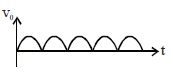
B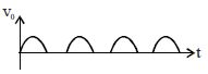
C
Zero.
D
None of these.
Solution
(A) The given circuit is a bridge rectifier circuit.
In a bridge rectifier,during the positive half-cycle of the input $AC$ signal,diodes $D_1$ and $D_3$ are forward-biased and conduct,while $D_2$ and $D_4$ are reverse-biased.
During the negative half-cycle,diodes $D_2$ and $D_4$ are forward-biased and conduct,while $D_1$ and $D_3$ are reverse-biased.
In both cases,the current flows through the load resistance $R_L$ in the same direction.
Therefore,the output voltage across the load resistance $R_L$ is a full-wave rectified signal.
0 likes
View Solution76
EasyMCQ
In the half wave rectifier circuit operating from $50\, Hz$ mains frequency,the fundamental frequency in the ripple would be......$ Hz$
A
$25$
B
$50$
C
$70.7$
D
$100$
Solution
(B) In a half-wave rectifier,the circuit allows only one half-cycle (either positive or negative) of the input alternating current $(AC)$ to pass through to the load.
Since the output consists of one pulse for every complete cycle of the input $AC$,the time period of the output ripple remains the same as the time period of the input $AC$ signal.
Therefore,the fundamental frequency of the ripple in a half-wave rectifier is equal to the input mains frequency.
Given the input frequency is $50\, Hz$,the fundamental frequency of the ripple is $50\, Hz$.
0 likes
View Solution77
Medium
In half-wave rectification,what is the output frequency if the input frequency is $50 \;Hz$? What is the output frequency of a full-wave rectifier for the same input frequency?
Solution
(N/A) Input frequency $= 50 \;Hz$.
For a half-wave rectifier,the output frequency is equal to the input frequency.
$\therefore$ Output frequency $= 50 \;Hz$.
For a full-wave rectifier,the output frequency is twice the input frequency.
$\therefore$ Output frequency $= 2 \times 50 = 100 \;Hz$.
For a half-wave rectifier,the output frequency is equal to the input frequency.
$\therefore$ Output frequency $= 50 \;Hz$.
For a full-wave rectifier,the output frequency is twice the input frequency.
$\therefore$ Output frequency $= 2 \times 50 = 100 \;Hz$.
0 likes
View Solution78
Medium
What is rectification and rectifier? Why is a $p-n$ junction diode used as a rectifier?
Solution
(N/A) Rectification is the process of converting alternating current $(AC)$ into direct current $(DC)$.
$A$ device that performs this process is called a rectifier.
$A$ $p-n$ junction diode is used as a rectifier because it exhibits unidirectional current flow properties.
When the diode is forward-biased,it offers very low resistance and allows current to flow.
When the diode is reverse-biased,it offers very high resistance and blocks the current flow.
This property allows the diode to conduct only during the positive half-cycle of the $AC$ input,effectively converting it into a pulsating $DC$ output.
0 likes
View Solution79
Medium
Write the principle of a rectifier.
Solution
(N/A) rectifier is an electrical device that converts alternating current $(AC)$,which periodically reverses direction,into direct current $(DC)$,which flows in only one direction.
The principle of a rectifier is based on the unidirectional property of a $p-n$ junction diode.
$A$ $p-n$ junction diode allows current to flow easily when it is forward-biased (low resistance) and blocks the flow of current when it is reverse-biased (high resistance).
By utilizing this property,the diode acts as a switch that conducts during the positive half-cycle of the $AC$ input and blocks during the negative half-cycle (or vice versa),thereby producing a pulsating $DC$ output.
0 likes
View Solution80
Difficult
Explain the use of the junction diode as a half-wave rectifier by drawing a circuit and draw input and output waves.
Solution
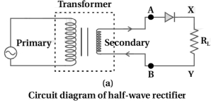
(N/A) half-wave rectifier consists of a transformer,a junction diode,and a load resistance $R_{L}$.
The primary coil of the transformer is connected to the $AC$ mains voltage. The secondary coil of the transformer is connected in series with the junction diode and the load resistance $R_{L}$. This circuit is called a half-wave rectifier.
The required $AC$ voltage is obtained between ends $A$ and $B$ of the secondary coil of the transformer.
During the first positive half-cycle of the $AC$ voltage,end $A$ is positive with respect to $B$. As a result,the $p-n$ junction diode is in forward bias,and current flows through the load resistance $R_{L}$ from direction $X$ to $Y$.
During the second half-cycle,$A$ becomes negative with respect to $B$. As a result,the $p-n$ junction diode is in reverse bias,and no current flows through the load resistance $R_{L}$.
Thus,during the positive half-cycle of incoming cycles,the current flows in $R_{L}$ in the $X$ to $Y$ direction.
The reverse saturated current for the diode is negligible and is ignored.
The reverse breakdown voltage of the diode must be sufficiently higher than the peak $AC$ voltage at the secondary of the transformer to protect the diode from reverse breakdown.
The $AC$ voltage across the ends of $R_{L}$ and the waveform of the rectified voltage are shown in the figure.
0 likes
View Solution81
Medium
Explain the use of a junction diode as a full-wave rectifier by drawing a circuit diagram and show the input and output waveforms.
Solution
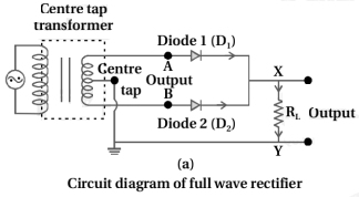
(N/A) full-wave rectifier consists of a center-tapped transformer,two junction diodes $D_{1}$ and $D_{2}$,and a load resistance $R_{L}$.
The primary coil of the transformer is connected to the a.c. supply. The $p$-sides of the two diodes are connected to the ends of the secondary coil of the transformer,and the $n$-sides are connected together to one end of the load resistance $R_{L}$. The other end of the load resistance is connected to the center tap of the secondary coil.
During the first half-cycle of the a.c. input,if the potential at $A$ is positive with respect to the center tap,diode $D_{1}$ is forward-biased and conducts,while diode $D_{2}$ is reverse-biased and does not conduct. Current flows through $R_{L}$ from $X$ to $Y$.
During the second half-cycle,the potential at $B$ becomes positive with respect to the center tap. Now,diode $D_{2}$ is forward-biased and conducts,while diode $D_{1}$ is reverse-biased. Current again flows through $R_{L}$ from $X$ to $Y$.
Since the current through the load resistance $R_{L}$ flows in the same direction during both half-cycles,a unidirectional (rectified) output is obtained across $R_{L}$.
0 likes
View Solution82
Medium
Describe the simple filter circuit for obtaining smooth rectified voltage from a junction diode rectifier.
Solution
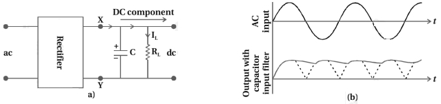
(N/A) The rectified voltage is in the form of pulses of the shape of half sinusoids. Although it is unidirectional,it does not have a steady value.
To get a steady $dc$ output from the pulsating voltage,normally a capacitor is connected across the output terminals parallel to the load $R_{L}$,or one can also use an inductor in series with $R_{L}$ for the same purpose. Since these additional circuits appear to filter out the $ac$ ripple and give a pure $dc$ voltage,they are called filters.
When the voltage across the capacitor is rising,it gets charged.
If there is no external load,it remains charged to the peak voltage of the rectified output.
When there is a load,it gets discharged through the load and the voltage across it begins to fall.
In the next half cycle of the rectified output,it again gets charged to the peak value. This is shown in the figure.
The rate of fall of the voltage across the capacitor depends inversely upon the product of capacitance $C$ and the effective resistance $R_{L}$ used in the circuit and is called the time constant $[t = RC]$.
To make the time constant large,the value of $C$ should be large.
So,capacitor input filters use large capacitors.
The output voltage obtained by using a capacitor input filter is nearer to the peak voltage of the rectified voltage.
This type of filter is most widely used in power supplies.
0 likes
View Solution83
Easy
What is rectification and rectifier?
Solution
(N/A) Rectification is the process of converting an alternating current $(AC)$ into a direct current $(DC)$.
$A$ rectifier is an electrical device that performs the process of rectification.
It typically uses one or more $p-n$ junction diodes,which allow current to flow in only one direction,thereby blocking the reverse half-cycle of the $AC$ input.
$A$ rectifier is an electrical device that performs the process of rectification.
It typically uses one or more $p-n$ junction diodes,which allow current to flow in only one direction,thereby blocking the reverse half-cycle of the $AC$ input.
0 likes
View Solution84
Easy
Why is a junction diode used for rectification?
Solution
(N/A) junction diode is used for rectification because it exhibits unidirectional current flow properties.
$1$. When the diode is forward-biased,it offers very low resistance,allowing current to pass through it easily.
$2$. When the diode is reverse-biased,it offers very high resistance,effectively blocking the current.
$3$. This property allows the diode to convert alternating current $(AC)$,which changes direction periodically,into direct current $(DC)$,which flows in only one direction.
$4$. By allowing current to flow only during the positive half-cycle of the $AC$ input,the diode acts as a rectifier.
0 likes
View Solution85
Easy
Write the types of rectifier.
Solution
(N/A) rectifier is an electrical device that converts alternating current $(AC)$,which periodically reverses direction,to direct current $(DC)$,which flows in only one direction. The process is known as rectification.
There are two main types of rectifiers based on the number of diodes used and the circuit configuration:
$1$. Half-wave rectifier: This type of rectifier uses only one diode. It converts only one half of the $AC$ input cycle into $DC$ output,while the other half is blocked. It is less efficient compared to full-wave rectifiers.
$2$. Full-wave rectifier: This type of rectifier converts both halves of the $AC$ input cycle into $DC$ output. It is further classified into two types:
- Center-tapped full-wave rectifier: Uses two diodes and a center-tapped transformer.
- Bridge rectifier: Uses four diodes arranged in a bridge configuration. It does not require a center-tapped transformer and is more commonly used in practical applications.
0 likes
View Solution86
EasyMCQ
How many junction diodes are used for half-wave and full-wave rectifiers,respectively?
A
$1$ and $2$
B
$2$ and $4$
C
$1$ and $4$
D
$2$ and $1$
Solution
(A) half-wave rectifier uses a single $p-n$ junction diode to convert alternating current $(AC)$ into pulsating direct current $(DC)$ by allowing current to flow only during the positive half-cycle of the input signal.
$A$ full-wave rectifier typically uses two diodes (with a center-tapped transformer) or four diodes (in a bridge rectifier configuration) to convert both the positive and negative half-cycles of the $AC$ input into pulsating $DC$.
In standard textbook contexts,a full-wave rectifier is most commonly associated with the bridge configuration using $4$ diodes,or the center-tapped configuration using $2$ diodes. Given the options provided,the standard answer for a half-wave rectifier is $1$ diode and for a full-wave rectifier is $2$ diodes (center-tapped) or $4$ diodes (bridge). Comparing with the options,$1$ and $2$ is the most appropriate choice for the basic configurations.
0 likes
View Solution87
MediumMCQ
What is a filter circuit?
A
$A$ circuit that converts $AC$ to $DC$.
B
$A$ circuit that removes the ripples from the pulsating $DC$ output of a rectifier.
C
$A$ circuit that amplifies the input signal.
D
$A$ circuit that maintains a constant voltage across the load.
Solution
(B) filter circuit is an electronic circuit designed to remove the unwanted $AC$ components (ripples) from the pulsating $DC$ output obtained from a rectifier.
It typically consists of passive components like capacitors $(C)$,inductors $(L)$,or a combination of both ($LC$ or $\pi$-filters).
The capacitor acts as a low-impedance path for $AC$ ripples to ground,while the inductor blocks $AC$ ripples due to its high inductive reactance $(X_L = 2\pi fL)$.
Thus,the filter circuit helps in obtaining a smooth,steady $DC$ voltage across the load.
0 likes
View Solution88
Medium
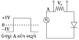
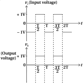
Draw the output waveform across the resistor for the given circuit and input waveform.
Solution
(N/A) The circuit consists of an input voltage source $v_{s}$,a resistor $R$,and a diode connected in series. The output voltage $v_{o}$ is measured across the resistor $R$.
The current $I$ in the circuit is given by:
$I = \frac{v_{i}}{R + R_{D}}$
where $R_{D}$ is the resistance of the diode.
$1$. During the positive half cycle of the input voltage $(v_{i} = +1 \text{ V})$,the diode is forward-biased. Assuming an ideal diode,$R_{D} = 0$. Therefore,the current $I = \frac{v_{i}}{R}$. The output voltage across the resistor is $v_{o} = I \cdot R = (\frac{v_{i}}{R}) \cdot R = v_{i} = +1 \text{ V}$.
$2$. During the negative half cycle of the input voltage $(v_{i} = -1 \text{ V})$,the diode is reverse-biased. For an ideal diode,$R_{D} = \infty$. Therefore,the current $I = 0$. The output voltage across the resistor is $v_{o} = I \cdot R = 0 \cdot R = 0 \text{ V}$.
Thus,the output waveform is a positive-going pulse train where the voltage is $+1 \text{ V}$ during the positive half cycle of the input and $0 \text{ V}$ during the negative half cycle.
0 likes
View Solution89
MediumMCQ
$A$ diode detector is used to detect an amplitude modulated wave of $60\%$ modulation by using a condenser of capacity $250\, pF$ in parallel with a load resistance $100\, k\Omega$. Find the maximum modulated frequency which could be detected by it.
A
$10.62\, MHz$
B
$10.61\, kHz$
C
$5.31\, MHz$
D
$5.31\, kHz$
Solution
(B) The condition for proper detection of an amplitude modulated signal without distortion is that the time constant $\tau = RC$ must satisfy the relation $\tau \le \frac{1}{\omega_m m_a}$,where $\omega_m = 2\pi f_m$ is the angular frequency of the modulating signal and $m_a$ is the modulation index.
Given:
$R = 100\, k\Omega = 10^5\, \Omega$
$C = 250\, pF = 250 \times 10^{-12}\, F$
$m_a = 60\% = 0.6$
The maximum frequency $f_m$ that can be detected is given by:
$f_m = \frac{1}{2\pi m_a RC}$
Calculating the time constant:
$\tau = RC = 10^5 \times 250 \times 10^{-12} = 2.5 \times 10^{-5}\, s$
Substituting the values:
$f_m = \frac{1}{2 \times 3.1416 \times 0.6 \times 2.5 \times 10^{-5}}$
$f_m = \frac{1}{9.4248 \times 10^{-5}}$
$f_m \approx 10610\, Hz = 10.61\, kHz$
0 likes
View Solution90
MediumMCQ
Match List $I$ with List $II$.
Choose the correct answer from the options given below:
| List $I$ | List $II$ |
| $(a)$ Rectifier | $(i)$ Used either for stepping up or stepping down the $a.c.$ voltage |
| $(b)$ Stabilizer | $(ii)$ Used to convert $a.c.$ voltage into $d.c.$ voltage |
| $(c)$ Transformer | $(iii)$ Used to remove any ripple in the rectified output voltage |
| $(d)$ Filter | $(iv)$ Used for constant output voltage even when the input voltage or load current change |
Choose the correct answer from the options given below:
A
$(a)-(ii), (b)-(iv), (c)-(i), (d)-(iii)$
B
$(a)-(iii), (b)-(iv), (c)-(i), (d)-(ii)$
C
$(a)-(ii), (b)-(i), (c)-(iv), (d)-(iii)$
D
$(a)-(ii), (b)-(i), (c)-(iii), (d)-(iv)$
Solution
(A) Rectifier: $A$ device used to convert alternating current $(a.c.)$ into direct current $(d.c.)$. Thus,$(a)-(ii)$.
$(b)$ Stabilizer: $A$ device used to maintain a constant output voltage even when the input voltage or load current changes. Thus,$(b)-(iv)$.
$(c)$ Transformer: $A$ device used to step up or step down the $a.c.$ voltage. Thus,$(c)-(i)$.
$(d)$ Filter: $A$ circuit used to remove any ripples (fluctuations) in the rectified output voltage to provide a smoother $d.c.$ output. Thus,$(d)-(iii)$.
Therefore,the correct matching is $(a)-(ii), (b)-(iv), (c)-(i), (d)-(iii)$.
0 likes
View Solution91
DifficultMCQ
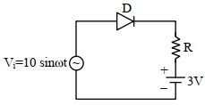
Choose the correct waveform that can represent the voltage across $R$ of the following circuit,assuming the diode is ideal one:
A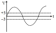
B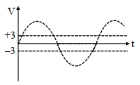
C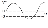
D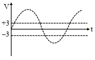
Solution
(A) The circuit consists of an $AC$ source $V_i = 10 \sin \omega t$,an ideal diode $D$,a resistor $R$,and a $3 \ V$ $DC$ battery in series.
For the diode to be forward-biased,the potential at the anode must be greater than the potential at the cathode.
The cathode is connected to the positive terminal of the $3 \ V$ battery.
Therefore,the diode conducts only when $V_i > 3 \ V$.
When $V_i > 3 \ V$,the diode acts as a short circuit (ideal diode). The voltage across the resistor $R$ is given by $V_R = V_i - 3 \ V$.
When $V_i \leq 3 \ V$,the diode is reverse-biased and acts as an open circuit. No current flows through the resistor $R$,so $V_R = 0 \ V$.
Thus,the waveform across $R$ will be a clipped sine wave that only exists when $V_i > 3 \ V$,with the peak value being $10 - 3 = 7 \ V$.
0 likes
View Solution92
MediumMCQ
Statement-$I$: To get a steady $DC$ output from the pulsating voltage received from a full wave rectifier,we can connect a capacitor across the output parallel to the load $R_L$.
Statement-$II$: To get a steady $DC$ output from the pulsating voltage received from a full wave rectifier,we can connect an inductor in series with $R_L$.
In the light of the above statements,choose the most appropriate answer from the options given below:
Statement-$II$: To get a steady $DC$ output from the pulsating voltage received from a full wave rectifier,we can connect an inductor in series with $R_L$.
In the light of the above statements,choose the most appropriate answer from the options given below:
A
Statement $I$ is true but Statement $II$ is false.
B
Statement $I$ is false but Statement $II$ is true.
C
Both Statement $I$ and Statement $II$ are false.
D
Both Statement $I$ and Statement $II$ are true.
Solution
(D) full-wave rectifier produces a pulsating $DC$ output. To smooth this output and obtain a steady $DC$ voltage,filter circuits are used.
$1$. $A$ capacitor connected in parallel to the load $R_L$ acts as a filter because it charges when the voltage increases and discharges through the load when the voltage decreases,thereby reducing ripples.
$2$. An inductor connected in series with the load $R_L$ also acts as a filter because it opposes any change in the current flowing through it,thereby smoothing the output current.
Since both methods are standard techniques for filtering pulsating $DC$ to obtain a steady $DC$ output,both Statement-$I$ and Statement-$II$ are true.
0 likes
View Solution93
EasyMCQ
In half wave rectification,if the input frequency is $60\,Hz$,then the output frequency would be $\dots\dots\dots\,Hz$.
A
$30$
B
$60$
C
$120$
D
Zero
Solution
(B) In a half-wave rectifier,the diode conducts only during the positive half-cycle of the input $AC$ signal.
Therefore,the output signal consists of one pulse for every complete cycle of the input signal.
As a result,the frequency of the output signal is equal to the frequency of the input signal.
Given that the input frequency $f_{\text{in}} = 60\,Hz$,the output frequency $f_{\text{out}}$ will also be $60\,Hz$.
0 likes
View Solution94
AdvancedMCQ
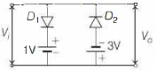
The figure below shows a circuit and its input voltage $V_i$ as a function of time $t$. Assuming the diodes to be ideal,which of the following graphs depicts the output voltage $V_o$ as a function of time $t$?
A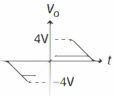
B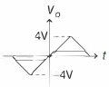
C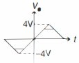
D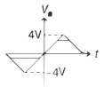
Solution
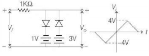
(A) The circuit consists of two diodes $D_1$ and $D_2$ in parallel with the output,each in series with a $DC$ voltage source.
$1$. For the positive half-cycle of $V_i$:
Diode $D_1$ is forward-biased when $V_i > 1 \, V$. Once $V_i$ exceeds $1 \, V$,$D_1$ conducts and clamps the output voltage $V_o$ to $1 \, V$. Thus,for $V_i > 1 \, V$,$V_o = 1 \, V$.
$2$. For the negative half-cycle of $V_i$:
Diode $D_2$ is forward-biased when $V_i < -3 \, V$. Once $V_i$ drops below $-3 \, V$,$D_2$ conducts and clamps the output voltage $V_o$ to $-3 \, V$. Thus,for $V_i < -3 \, V$,$V_o = -3 \, V$.
$3$. For the range $-3 \, V \leq V_i \leq 1 \, V$:
Both diodes are reverse-biased and do not conduct. Therefore,the output voltage follows the input voltage,i.e.,$V_o = V_i$.
Comparing this behavior with the given options,the graph that shows the output voltage clamped at $1 \, V$ for positive inputs and $-3 \, V$ for negative inputs is the correct representation.
0 likes
View Solution95
EasyMCQ
The value of the form factor in the case of a half-wave rectifier is
A
$1.11$
B
$1.57$
C
$1.27$
D
$0.48$
Solution
(B) The form factor is defined as the ratio of the root mean square $(RMS)$ value to the average value of the output voltage.
Form factor $= \frac{V_{\text{rms}}}{V_{\text{avg}}}$
For a half-wave rectifier,the $RMS$ value of the output voltage is $V_{\text{rms}} = \frac{V_{\text{max}}}{2}$.
The average value of the output voltage is $V_{\text{avg}} = \frac{V_{\text{max}}}{\pi}$.
Therefore,the form factor $= \frac{V_{\text{max}} / 2}{V_{\text{max}} / \pi} = \frac{\pi}{2} \approx 1.57$.
0 likes
View Solution96
EasyMCQ
The maximum efficiency of a full wave rectifier is .........
A
$\frac{4}{\pi^2} \times 100 \,\%$
B
$\frac{8}{\pi^2} \times 100 \,\%$
C
$40 \,\%$
D
$80 \,\%$
Solution
(B) The efficiency $(\eta)$ of a rectifier is defined as the ratio of the $DC$ output power to the $AC$ input power.
For a full-wave rectifier,the $DC$ output power is $P_{dc} = I_{dc}^2 R_L = (\frac{2I_m}{\pi})^2 R_L = \frac{4I_m^2 R_L}{\pi^2}$.
The $AC$ input power is $P_{ac} = I_{rms}^2 (R_f + R_L) = (\frac{I_m}{\sqrt{2}})^2 (R_f + R_L) = \frac{I_m^2}{2} (R_f + R_L)$.
Assuming the diode resistance $R_f$ is negligible compared to the load resistance $R_L$,the efficiency is $\eta = \frac{P_{dc}}{P_{ac}} = \frac{4I_m^2 R_L / \pi^2}{I_m^2 R_L / 2} = \frac{8}{\pi^2}$.
Converting this to a percentage,the maximum efficiency is $\frac{8}{\pi^2} \times 100 \% \approx 81.2 \%$.
0 likes
View Solution97
EasyMCQ
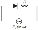
In the circuit shown,the average power dissipated in the resistor is (assume diode to be ideal).
A
$\frac{E_0^2}{2 R}$
B
$\frac{E_0^2}{4 R}$
C
$\frac{E_0^2}{R}$
D
Zero
Solution
(B) The circuit represents a half-wave rectifier where the diode conducts only during the positive half-cycle of the input $AC$ voltage $E = E_0 \sin \omega t$.
For a half-wave rectified sine wave,the root mean square $(RMS)$ voltage is given by $E_{rms} = \frac{E_0}{2}$.
The average power dissipated in the resistor $R$ is calculated using the formula $P_{av} = \frac{E_{rms}^2}{R}$.
Substituting the value of $E_{rms}$,we get $P_{av} = \frac{(\frac{E_0}{2})^2}{R} = \frac{E_0^2}{4R}$.
0 likes
View Solution98
EasyMCQ
$A$ full wave rectifier circuit consists of two $p-n$ junction diodes,a centre-tapped transformer,a capacitor,and a load resistance. Which of these components removes the $AC$ ripple from the rectified output?
A
Load resistance
B
$A$ centre-tapped transformer
C
$p-n$ junction diodes
D
Capacitor
Solution
(D) In a rectifier circuit,the output contains $AC$ ripples (fluctuations).
To obtain a smooth $DC$ output,a filter circuit is used.
$A$ capacitor is connected in parallel with the load resistance to act as a filter.
The capacitor charges when the output voltage increases and discharges through the load when the output voltage decreases,thereby smoothing out the ripples.
Therefore,the capacitor is the component that removes $AC$ ripples from the rectified output.
0 likes
View Solution99
MediumMCQ
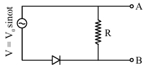
In the circuit shown here, assuming the threshold voltage of the diode is negligibly small, the voltage $V_{A B}$ is correctly represented by which of the following graphs?
A
$V_{A B}$ would be zero at all times
B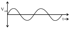
C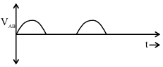
D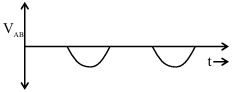
Solution
(D) The circuit consists of an $AC$ source $V = V_{0} \sin \omega t$ in series with a diode and a resistor $R$. The output voltage $V_{A B}$ is measured across the resistor $R$.
During the positive half-cycle of the input $AC$, the diode is reverse-biased ($R.B.$). Since the diode acts as an open circuit in reverse bias, no current flows through the resistor $R$, and thus $V_{A B} = 0$.
During the negative half-cycle of the input $AC$, the diode is forward-biased ($F.B.$). Since the threshold voltage is negligible, the diode acts as a short circuit. The entire input voltage appears across the resistor $R$. However, because the input voltage is negative during this half-cycle, $V_{A B}$ will also be negative.
Therefore, the output voltage $V_{A B}$ will show negative half-cycles corresponding to the negative half-cycles of the input, and zero during the positive half-cycles. This matches the graph shown in option $D$.
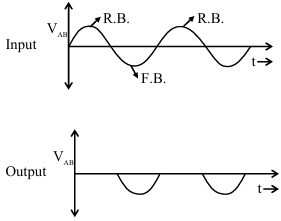
0 likes
View SolutionSemiconductor Electronics — Application of junction diode (Rectifier) · Frequently Asked Questions
1Are these Semiconductor Electronics questions useful for JEE and NEET?
Yes. All questions in this section are mapped to JEE Main and NEET exam patterns. Previous year questions from JEE Main, NEET, GUJCET and state-level exams are included with full solutions.
2Can I switch to Hindi or Gujarati for these questions?
Yes. Use the language tabs in the hero section or the sidebar to view the same questions and solutions in English, Hindi or Gujarati.
3How do I generate a question paper from this subtopic?
Use the Vedclass Exam Paper Generator — select the chapter and subtopic, set difficulty, and generate Sets A, B, C, D automatically. First 3 chapters of every subject are free.
Vedclass Products
For Students
Vedclass Test Series
Mock tests in real JEE/NEET style with performance analysis. 5-day free trial.
Start Free TrialFor Teachers
Exam Paper Generator
Generate Set A/B/C/D papers from this chapter in 2 minutes. 3 chapters free.
Try FreeFor Institutes
Online Exam Module
Live online exams with unlimited students, 360° analytics & white-label branding.
See DemoFor Teachers & Institutes
Generate a Semiconductor Electronics Exam Paper in 2 Minutes
Select subtopic & difficulty — Sets A, B, C, D auto-generated with No Repeat logic.
First 3 chapters of every subject are free — no payment required.