
A English
Application of junction diode (Rectifier) Questions in English
Class 12 Physics · Semiconductor Electronics · Application of junction diode (Rectifier)
129+
Questions
English
Language
100%
With Solutions
Showing 28 of 129 questions in English
101
DifficultMCQ
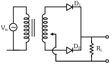
$A$ full-wave rectifier circuit with diodes $D_1$ and $D_2$ is shown in the figure. If the input supply voltage is $V_{in} = 220 \sin(100 \pi t) \ V$, then at $t = 15 \ ms$:
A
$D_1$ is forward biased, $D_2$ is reverse biased
B
$D_1$ is reverse biased, $D_2$ is forward biased
C
$D_1$ and $D_2$ both are forward biased
D
$D_1$ and $D_2$ both are reverse biased
Solution
(B) Given the input voltage $V_{in} = 220 \sin(100 \pi t) \ V$.
At time $t = 15 \ ms = 15 \times 10^{-3} \ s$, the input voltage is:
$V_{in} = 220 \sin(100 \pi \times 15 \times 10^{-3})$
$V_{in} = 220 \sin(1.5 \pi) = 220 \sin\left(\frac{3\pi}{2}\right)$
$V_{in} = 220 \times (-1) = -220 \ V$.
In a center-tapped full-wave rectifier, when the potential at the top terminal of the secondary coil is negative with respect to the center tap, diode $D_1$ is reverse biased and diode $D_2$ is forward biased.
0 likes
View Solution102
MediumMCQ
Match List-$I$ with List-$II$:
| List-$I$ | List-$II$ |
| $(a)$ Rectifier | $(i)$ Used for stepping up or stepping down the $\text{A.C.}$ voltage |
| $(b)$ Stabilizer | $(ii)$ Used to convert $\text{A.C.}$ voltage into $\text{D.C.}$ voltage |
| $(c)$ Transformer | $(iii)$ Used to remove any ripple in the rectified output voltage |
| $(d)$ Filter | $(iv)$ Used for constant output voltage |
A
$a-(ii), b-(iv), c-(i), d-(iii)$
B
$a-(iii), b-(iv), c-(i), d-(ii)$
C
$a-(ii), b-(i), c-(iv), d-(iii)$
D
$a-(ii), b-(i), c-(iii), d-(iv)$
Solution
(A) The correct matches are as follows:
$1$. Rectifier: $A$ device used to convert $\text{A.C.}$ voltage into $\text{D.C.}$ voltage. Thus,$(a)-(ii)$.
$2$. Stabilizer: $A$ device used to maintain a constant output voltage despite fluctuations in input voltage. Thus,$(b)-(iv)$.
$3$. Transformer: $A$ device used for stepping up or stepping down the $\text{A.C.}$ voltage. Thus,$(c)-(i)$.
$4$. Filter: $A$ circuit used to remove ripples (fluctuations) from the rectified output voltage to obtain a smoother $\text{D.C.}$ signal. Thus,$(d)-(iii)$.
Therefore,the correct sequence is $a-(ii), b-(iv), c-(i), d-(iii)$.
0 likes
View Solution103
MediumMCQ
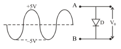
If in a $p-n$ junction,a sinusoidal input signal is applied at $A$ as shown,then the output voltage $V_0$ will be:
A
B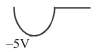
C
D
Solution
(C) The circuit shown is a parallel combination of a diode $D$ and the output terminals.
During the positive half-cycle of the input signal,the diode $D$ is forward-biased $(FB)$. An ideal diode in forward bias acts as a short circuit,meaning the potential difference across it is $0 \ V$. Thus,the output voltage $V_0$ becomes $0 \ V$.
During the negative half-cycle of the input signal,the diode $D$ is reverse-biased $(RB)$. An ideal diode in reverse bias acts as an open circuit,meaning no current flows through it. Thus,the entire input voltage appears across the output terminals. Therefore,the output voltage $V_0$ follows the input signal,which is $-5 \ V$ at its peak.
Combining these,the output is a half-wave rectified signal showing only the negative half-cycle with a peak of $-5 \ V$.
0 likes
View Solution104
EasyMCQ
If a full wave rectifier circuit is operating from $50 \,Hz$ mains, the fundamental frequency in the ripple will be (in $\,Hz$)
A
$70.7$
B
$100$
C
$25$
D
$59$
Solution
(B) In a full wave rectifier, the output consists of two pulses for every single cycle of the input $AC$ supply.
Therefore, the ripple frequency is twice the input frequency.
Given, input frequency $f = 50 \,Hz$.
Ripple frequency $= 2 \times f = 2 \times 50 \,Hz = 100 \,Hz$.
Therefore, the ripple frequency is twice the input frequency.
Given, input frequency $f = 50 \,Hz$.
Ripple frequency $= 2 \times f = 2 \times 50 \,Hz = 100 \,Hz$.
0 likes
View Solution105
EasyMCQ
If an alternating voltage is applied across a $p-n$ junction diode in series with a load,then:
A
no voltage appears across load.
B
a pulsating voltage appears across load.
C
an $a.c.$ voltage appears across load.
D
a $d.c.$ voltage appears across load which is not pulsating.
Solution
(B) When an alternating voltage is applied to a $p-n$ junction diode in series with a load,the diode acts as a rectifier.
During the positive half-cycle of the input $a.c.$ signal,the diode is forward-biased and conducts current,allowing voltage to appear across the load.
During the negative half-cycle,the diode is reverse-biased and does not conduct,resulting in zero voltage across the load.
Consequently,the output voltage across the load is unidirectional but varies with time,which is known as a pulsating $d.c.$ voltage.
0 likes
View Solution106
MediumMCQ
If a centre-tap transformer is used with two $p-n$ junction diodes for full-wave rectification,then the output voltage of the rectifier with respect to each diode is (secondary voltage of transformer $= V_s$)
A
$2 V_s$
B
$\frac{2}{3} V_s$
C
$\frac{1}{2} V_s$
D
$\frac{3}{2} V_s$
Solution
(C) In a centre-tap full-wave rectifier,the secondary winding of the transformer is divided into two equal halves by the centre tap.
If the total secondary voltage across the entire secondary winding is $V_s$,then the voltage across each half of the secondary winding is $\frac{V_s}{2}$.
During the positive half-cycle,one diode conducts and the voltage across the load is the voltage across the top half of the secondary,which is $\frac{V_s}{2}$.
During the negative half-cycle,the other diode conducts and the voltage across the load is the voltage across the bottom half of the secondary,which is also $\frac{V_s}{2}$.
Therefore,the output voltage with respect to each diode is $\frac{1}{2} V_s$.
0 likes
View Solution107
EasyMCQ
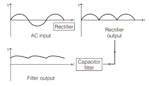
In the block diagram of a simple rectifier circuit,from a variable $A.C.$ voltage,constant $D.C.$ voltage is obtained. The correct order of operation is
A
voltage regulator,diode rectifier,filter.
B
diode rectifier,voltage regulator,filter.
C
diode rectifier,filter,voltage regulator.
D
filter,voltage regulator,diode rectifier.
Solution
(C) $1$. Diode Rectifier: This is the first stage,where the $A.C.$ voltage is rectified to produce a pulsating $D.C.$ voltage. The diode$(s)$ in the rectifier allow current to flow only in one direction,converting the $A.C.$ input into a unidirectional current.
$2$. Filter: After rectification,the output is a pulsating $D.C.$ that still contains ripples. $A$ filter (usually a capacitor or a combination of capacitors and inductors) smooths out these ripples,providing a more steady $D.C.$ output.
$3$. Voltage Regulator: The final stage is the voltage regulator,which ensures that the $D.C.$ voltage remains constant,even if the input $A.C.$ voltage fluctuates or if there are variations in load. The regulator keeps the output voltage at a constant level by adjusting the current flow as needed.
Therefore,the correct order of operation is:
- Diode rectifier $\rightarrow$ Filter $\rightarrow$ Voltage regulator
0 likes
View Solution108
EasyMCQ
$A$ $p-n$ junction diode as a rectifier converts
A
$a.c.$ to $d.c.$
B
$d.c.$ to $a.c.$
C
high voltage to low voltage.
D
low voltage to high voltage.
Solution
(A) The correct answer is $a.c.$ to $d.c.$.
$A$ rectifier is an electrical device that converts alternating current $(AC)$,which periodically reverses direction,to direct current $(DC)$,which flows in only one direction.
Since a $p-n$ junction diode allows current to flow only in one direction (forward bias),it acts as a rectifier.
$A$ rectifier is an electrical device that converts alternating current $(AC)$,which periodically reverses direction,to direct current $(DC)$,which flows in only one direction.
Since a $p-n$ junction diode allows current to flow only in one direction (forward bias),it acts as a rectifier.
0 likes
View Solution109
MediumMCQ
If the frequency of the input voltage is $50 \,Hz$, applied to a $(a)$ half-wave rectifier and $(b)$ full-wave rectifier, what is the output frequency in both cases, respectively?
A
$50 \,Hz, 50 \,Hz$
B
$50 \,Hz, 100 \,Hz$
C
$100 \,Hz, 100 \,Hz$
D
$100 \,Hz, 50 \,Hz$
Solution
(B) In a half-wave rectifier, the output pulse occurs once per input cycle. Therefore, the output frequency is equal to the input frequency, which is $50 \,Hz$.
In a full-wave rectifier, the output pulse occurs twice per input cycle (once for each half-cycle). Therefore, the output frequency is double the input frequency, which is $2 \times 50 \,Hz = 100 \,Hz$.
Thus, the output frequencies are $50 \,Hz$ and $100 \,Hz$ respectively.
In a full-wave rectifier, the output pulse occurs twice per input cycle (once for each half-cycle). Therefore, the output frequency is double the input frequency, which is $2 \times 50 \,Hz = 100 \,Hz$.
Thus, the output frequencies are $50 \,Hz$ and $100 \,Hz$ respectively.
0 likes
View Solution110
EasyMCQ
If the maximum efficiency of a full wave rectifier is $x \%$ and that of a half wave rectifier is $y \%$,then the relation between $x$ and $y$ is
A
$x=y$
B
$y=2x$
C
$x=2y$
D
$y=4x$
Solution
(C) The maximum efficiency of a full wave rectifier is given by $x = 81.2 \%$.
The maximum efficiency of a half wave rectifier is given by $y = 40.6 \%$.
Comparing these two values,we find that $x = 2 \times 40.6 \% = 2y$.
Therefore,the correct relation is $x = 2y$.
The maximum efficiency of a half wave rectifier is given by $y = 40.6 \%$.
Comparing these two values,we find that $x = 2 \times 40.6 \% = 2y$.
Therefore,the correct relation is $x = 2y$.
0 likes
View Solution111
EasyMCQ
In a full-wave rectifier circuit without a filter,the output current is
A
unidirectional but not steady current.
B
an eddy current.
C
a sinusoidal current.
D
a constant direct current.
Solution
(A) full-wave rectifier converts both halves of the input $AC$ cycle into a single polarity. Without a filter,the output consists of a series of pulsating pulses that are always in the same direction (unidirectional). However,because the magnitude of the current varies with time,it is not a steady or constant $DC$. Therefore,the output is a unidirectional but not steady current.
0 likes
View Solution112
EasyMCQ
$A$ rectifier is used to
A
convert $a.c.$ to $d.c.$
B
amplify a weak signal
C
generate intermittent voltage
D
convert $d.c.$ to $a.c.$
Solution
(A) rectifier is an electrical device that converts alternating current $(a.c.)$,which periodically reverses direction,into direct current $(d.c.)$,which flows in only one direction. This process is known as rectification. It typically uses one or more $p-n$ junction diodes to achieve this conversion.
0 likes
View Solution113
EasyMCQ
The frequency of a given $AC$ signal is $N \ Hz$. When it is connected to a half-wave rectifier,the number of output pulses given by the rectifier in $1 \ s$ is:
A
$\frac{N}{4}$
B
$\frac{N}{2}$
C
$N$
D
$2N$
Solution
(C) In an $AC$ signal with frequency $N \ Hz$,there are $N$ complete cycles per second.
In a half-wave rectifier,the diode conducts only during the positive half-cycle of the input $AC$ signal and blocks the negative half-cycle.
Therefore,for every complete cycle of the input $AC$ signal,the rectifier produces exactly one output pulse.
Since there are $N$ cycles per second,the number of output pulses produced by the half-wave rectifier in $1 \ s$ is $N$.
0 likes
View Solution114
MediumMCQ
The input a.c. voltage of frequency $60 \,Hz$ is applied to a half-wave rectifier and also to a full-wave rectifier. The output frequency in the case of the half-wave rectifier and that in the case of the full-wave rectifier is respectively:
A
$120 \,Hz, 60 \,Hz$
B
$60 \,Hz, 120 \,Hz$
C
$60 \,Hz, 60 \,Hz$
D
$120 \,Hz, 120 \,Hz$
Solution
(B) In a half-wave rectifier,the diode conducts only during the positive half-cycle of the input $a.c.$ signal. Therefore,the output frequency is equal to the input frequency,which is $60 \,Hz$.
In a full-wave rectifier,the circuit conducts during both the positive and negative half-cycles of the input $a.c.$ signal. This results in two output pulses for every single input cycle. Therefore,the output frequency is double the input frequency,which is $2 \times 60 \,Hz = 120 \,Hz$.
In a full-wave rectifier,the circuit conducts during both the positive and negative half-cycles of the input $a.c.$ signal. This results in two output pulses for every single input cycle. Therefore,the output frequency is double the input frequency,which is $2 \times 60 \,Hz = 120 \,Hz$.
0 likes
View Solution115
EasyMCQ
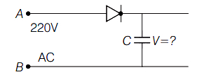
$A$ $220 \,V$ $AC$ supply is connected between points $A$ and $B$ as shown in the figure. What will be the potential difference $V$ across the capacitor?
A
$220 \,V$
B
$110 \,V$
C
zero
D
$220 \sqrt{2} \,V$
Solution
(D) The circuit acts as a half-wave rectifier with a capacitor filter.
When the $AC$ supply is connected, the $p-n$ junction diode conducts only during the positive half-cycle (forward biased condition).
During this cycle, the capacitor charges to the peak value of the input $AC$ voltage.
Once charged, the capacitor maintains this peak voltage as there is no discharge path provided in the circuit.
The potential difference $V$ across the capacitor is equal to the peak value of the input $AC$ voltage $(V_0)$.
Given that the $RMS$ voltage $V_{\text{rms}} = 220 \,V$, the peak voltage is calculated as:
$V = V_0 = V_{\text{rms}} \times \sqrt{2}$
$V = 220 \times \sqrt{2} \,V = 220 \sqrt{2} \,V$.
0 likes
View Solution116
EasyMCQ
$A$ full-wave rectifier with diodes $D_1$ and $D_2$ is used to rectify $50 \,Hz$ alternating voltage. The diode $D_1$ conducts .......... times in one second.
A
$100$
B
$25$
C
$75$
D
$50$
Solution
(D) In a full-wave rectifier, one diode conducts during the positive half-cycle, and the other diode conducts during the negative half-cycle of the input alternating voltage.
Since one complete cycle consists of one positive half-cycle and one negative half-cycle, each diode conducts exactly once per complete cycle.
Given the frequency of the $AC$ supply is $50 \,Hz$, which means there are $50$ complete cycles in $1 \,s$.
Therefore, the diode $D_1$ conducts $50$ times in $1 \,s$.
0 likes
View Solution117
MediumMCQ
Constant $DC$ voltage is required from a variable $AC$ voltage. Which of the following is the correct order of operation?
A
Regulator,filter,rectifier
B
Rectifier,regulator,filter
C
Rectifier,filter,regulator
D
Filter,regulator,rectifier
Solution
(C) To obtain a constant $DC$ voltage from a variable $AC$ source,the following operations must be performed in sequence:
$1$. Rectifier: It converts the $AC$ signal into a pulsating $DC$ signal.
$2$. Filter: The pulsating $DC$ signal is smoothed to remove ripples,converting it into a steady $DC$ signal.
$3$. Regulator: It provides a stable $DC$ voltage that is independent of load current and $AC$ source voltage variations.
0 likes
View Solution118
EasyMCQ
$A$ $PN$ junction diode is used as:
A
An amplifier
B
$A$ rectifier
C
An oscillator
D
$A$ modulator
Solution
(B) $PN$ junction diode allows current to flow in only one direction (forward bias) and blocks it in the opposite direction (reverse bias). This property makes it ideal for converting alternating current $(AC)$ into direct current $(DC)$,a process known as rectification. Therefore,a $PN$ junction diode is used as a rectifier.
0 likes
View Solution119
EasyMCQ
$A$ full-wave rectifier circuit is operating from $50 \text{ Hz}$ mains. The fundamental frequency in the ripple output will be: (in $\text{ Hz}$)
A
$50$
B
$70.7$
C
$100$
D
$25$
Solution
(C) In a full-wave rectifier, the output consists of two pulses for every cycle of the input $AC$ signal.
Therefore, the fundamental frequency of the output ripple is twice the input frequency.
Given, input frequency $f_{in} = 50 \text{ Hz}$.
Fundamental frequency of output ripple $f_0 = 2 \times f_{in} = 2 \times 50 \text{ Hz} = 100 \text{ Hz}$.
Therefore, the fundamental frequency of the output ripple is twice the input frequency.
Given, input frequency $f_{in} = 50 \text{ Hz}$.
Fundamental frequency of output ripple $f_0 = 2 \times f_{in} = 2 \times 50 \text{ Hz} = 100 \text{ Hz}$.
0 likes
View Solution120
MediumMCQ
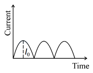
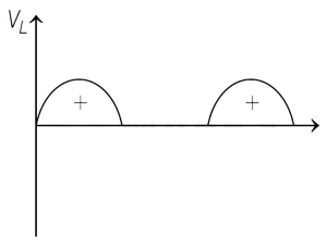
The output current versus time curve of a rectifier is shown in the figure. The average value of output current in this case is
A
$0$
B
$\frac{I_0}{2}$
C
$\frac{2 I_0}{\pi}$
D
$I_0$
Solution
(C) From the given figure,it is evident that the rectifier is a full-wave rectifier.
For a full-wave rectifier,the output current is given by $I = I_0 \sin(\omega t)$ for the first half-cycle and $I = I_0 \sin(\omega t)$ for the second half-cycle (due to rectification).
The average value of the current over one complete cycle $T$ is given by:
$I_{\text{avg}} = \frac{1}{T} \int_{0}^{T} I(t) dt$
For a full-wave rectifier,the period is $T/2$. The average value is calculated as:
$I_{\text{avg}} = \frac{1}{T/2} \int_{0}^{T/2} I_0 \sin(\omega t) dt$
$I_{\text{avg}} = \frac{2}{T} \cdot I_0 \left[ -\frac{\cos(\omega t)}{\omega} \right]_{0}^{T/2}$
Since $\omega = \frac{2\pi}{T}$,we have:
$I_{\text{avg}} = \frac{2 I_0}{T} \cdot \frac{T}{2\pi} [-\cos(\pi) + \cos(0)]$
$I_{\text{avg}} = \frac{I_0}{\pi} [1 + 1] = \frac{2 I_0}{\pi}$
0 likes
View Solution121
MediumMCQ
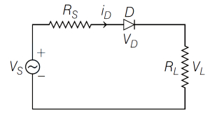
In the diode-based rectifier circuit given below,if $V_s=V_m \sin \omega t$ and the diode is ideal,then the average value of $V_L$ is
A
$\frac{R_L}{\left(R_L+R_S\right)} \frac{V_m}{\pi}$
B
$R_L V_m \sin \omega t$
C
$\frac{R_L}{\left(R_L+R_S\right)} V_m$
D
$\frac{R_L}{\left(R_L+R_S\right)} V_m \sin \omega t$
Solution
(A) Given,$AC$ voltage,$V_s=V_m \sin \omega t$,where $V_m$ is the maximum value of the voltage.
In the given half-wave rectifier circuit,the diode conducts only during the positive half-cycle of the input $AC$ signal.
For an ideal diode,the voltage across the load $R_L$ during the conduction period is given by the voltage divider rule: $V_{L,peak} = V_m \cdot \frac{R_L}{R_S+R_L}$.
The average value of a half-wave rectified sine wave is given by $V_{av} = \frac{V_{peak}}{\pi}$.
Substituting the peak voltage across the load,we get:
$V_{L,av} = \frac{V_{L,peak}}{\pi} = \frac{V_m}{\pi} \cdot \frac{R_L}{R_S+R_L} = \frac{R_L}{R_S+R_L} \cdot \frac{V_m}{\pi}$.
0 likes
View Solution122
MediumMCQ
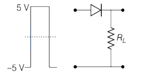
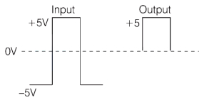
If in a $p-n$ junction diode, a square input signal of $5 \,V$ to $-5 \,V$ is applied as shown, then the output signal across $R_L$ will be:
A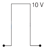
B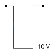
C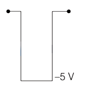
D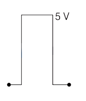
Solution
(D) $p-n$ junction diode acts as a rectifier.
When the input signal is positive $(+5 \,V)$, the diode is in forward bias and conducts current, allowing the signal to appear across the load resistor $R_L$.
When the input signal is negative $(-5 \,V)$, the diode is in reverse bias and acts as an open circuit, blocking the current.
Therefore, the output across $R_L$ will only show the positive half of the input signal, resulting in a square wave with a peak at $5 \,V$ and $0 \,V$ during the negative cycle.
0 likes
View Solution123
MediumMCQ
Normally,a capacitor is connected across the output terminals of a rectifier to
A
convert $AC$ to $DC$
B
convert $DC$ to $AC$
C
get a varying $DC$ output
D
get a steady $DC$ output
Solution
(D) rectifier converts $AC$ into pulsating $DC$. To remove the ripples and obtain a smooth or steady $DC$ output,a capacitor is connected in parallel across the output terminals. The capacitor acts as a filter by charging during the peak of the pulse and discharging during the valley,thereby smoothing out the voltage fluctuations.
0 likes
View Solution124
EasyMCQ
Normally,a capacitor is connected across the output terminals of a rectifier to
A
convert $AC$ to $DC$
B
convert $DC$ to $AC$
C
to get a varying $DC$ output
D
to get a steady $DC$ output
Solution
(D) rectifier converts $AC$ into a pulsating $DC$. To obtain a steady $DC$ output,a filter circuit is used. $A$ capacitor connected in parallel to the output terminals acts as a filter because it charges during the peak of the pulsating $DC$ and discharges when the voltage drops,thereby smoothing the output and providing a steady $DC$ voltage.
0 likes
View Solution125
EasyMCQ
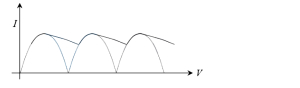
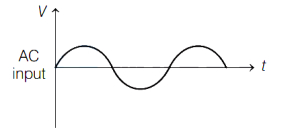
Which of the following depicts the output of the full-wave rectifier with a capacitor filter for the given $AC$ input?
A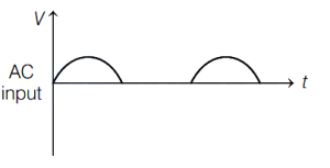
B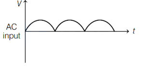
C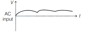
D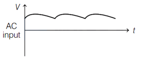
Solution
(D) full-wave rectifier converts both halves of the $AC$ input cycle into a pulsating $DC$ output.
When a capacitor filter is connected in parallel with the load,it charges during the rising part of the rectified output voltage and discharges through the load during the falling part.
This process reduces the ripple in the output voltage,resulting in a smoother $DC$ output that does not drop to zero.
Among the given options,the graph that shows a pulsating $DC$ output that remains above zero due to the filtering action of the capacitor is represented by option $D$.
0 likes
View Solution126
EasyMCQ
In a half-wave rectifier, an $AC$ input source of frequency $50 \,Hz$ is used. The fundamental frequency of the output is: (in $\,Hz$)
A
$50$
B
$150$
C
$200$
D
$75$
Solution
(A) In a half-wave rectifier, the diode conducts only during the positive half-cycle of the input $AC$ signal.
Since the output consists of one pulse for every full cycle of the input, the frequency of the output signal is equal to the frequency of the input signal.
Therefore, for an input frequency of $50 \,Hz$, the fundamental frequency of the output is $50 \,Hz$.
Since the output consists of one pulse for every full cycle of the input, the frequency of the output signal is equal to the frequency of the input signal.
Therefore, for an input frequency of $50 \,Hz$, the fundamental frequency of the output is $50 \,Hz$.
0 likes
View Solution127
MediumMCQ
If the output frequency of a full-wave rectifier is $100 \text{ Hz}$,then the input frequency will be . . . . . . . (in $\text{ Hz}$)
A
$50$
B
$200$
C
$100$
D
$25$
Solution
(A) For a full-wave rectifier,the output frequency $(f_{out})$ is twice the input frequency $(f_{in})$.
The relationship is given by the formula: $f_{out} = 2 \times f_{in}$.
Given that the output frequency $(f_{out})$ is $100 \text{ Hz}$.
Substituting the value into the formula: $100 \text{ Hz} = 2 \times f_{in}$.
Therefore,$f_{in} = \frac{100 \text{ Hz}}{2} = 50 \text{ Hz}$.
The relationship is given by the formula: $f_{out} = 2 \times f_{in}$.
Given that the output frequency $(f_{out})$ is $100 \text{ Hz}$.
Substituting the value into the formula: $100 \text{ Hz} = 2 \times f_{in}$.
Therefore,$f_{in} = \frac{100 \text{ Hz}}{2} = 50 \text{ Hz}$.
0 likes
View Solution128
MediumMCQ
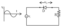
In the circuit shown below,the voltage appearing across the diode $D$ will be of the form:
A
B
C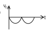
D
Solution
(D) The diode $D$ is in a half-wave rectifier configuration.
During the positive half-cycle of the input voltage $v_i$,the diode is forward-biased and acts as a short circuit (assuming an ideal diode),so the voltage drop across it is $v_D = 0$.
During the negative half-cycle,the diode is reverse-biased and acts as an open circuit,meaning no current flows through the resistor $R$. Consequently,the entire input voltage $v_i$ appears across the diode $D$,so $v_D = v_i$.
Therefore,the voltage across the diode $D$ follows the input wave only during the negative half-cycle,which corresponds to the waveform shown in option $D$.
0 likes
View SolutionSemiconductor Electronics — Application of junction diode (Rectifier) · Frequently Asked Questions
1Are these Semiconductor Electronics questions useful for JEE and NEET?
Yes. All questions in this section are mapped to JEE Main and NEET exam patterns. Previous year questions from JEE Main, NEET, GUJCET and state-level exams are included with full solutions.
2Can I switch to Hindi or Gujarati for these questions?
Yes. Use the language tabs in the hero section or the sidebar to view the same questions and solutions in English, Hindi or Gujarati.
3How do I generate a question paper from this subtopic?
Use the Vedclass Exam Paper Generator — select the chapter and subtopic, set difficulty, and generate Sets A, B, C, D automatically. First 3 chapters of every subject are free.
Vedclass Products
For Students
Vedclass Test Series
Mock tests in real JEE/NEET style with performance analysis. 5-day free trial.
Start Free TrialFor Teachers
Exam Paper Generator
Generate Set A/B/C/D papers from this chapter in 2 minutes. 3 chapters free.
Try FreeFor Institutes
Online Exam Module
Live online exams with unlimited students, 360° analytics & white-label branding.
See DemoFor Teachers & Institutes
Generate a Semiconductor Electronics Exam Paper in 2 Minutes
Select subtopic & difficulty — Sets A, B, C, D auto-generated with No Repeat logic.
First 3 chapters of every subject are free — no payment required.