
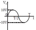
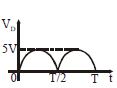
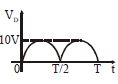
In the circuit shown in the figure, determine the output waveform and the output d.c. level of $V_0$.
- A
- B
- C
- DNone of these
Explore More
Similar Questions
$A$ sinusoidal peak voltage of $15\ V$ is connected between the input terminals of the circuit shown in the figure. Assume the diodes are ideal. In the output waveform,
Medium
View SolutionIf a full wave rectifier circuit is operating from $50\, Hz$ mains,the fundamental frequency in the ripple will be........$Hz$.
The frequency of the input $a.c.$ of a full-wave rectifier is $50\,Hz$. The frequency of the output is.....$Hz$.
Medium
View Solution$A$ waveform shown is applied to the following circuit. Assuming an ideal diode configuration and $R_1 = R_2$, which of the following output waveforms will be produced?
Difficult
View SolutionWhat is a filter circuit?
Medium
View SolutionVedclass Products
For Students
Vedclass Test Series
Mock tests in real JEE/NEET style with performance analysis. 5-day free trial.
Start Free TrialFor Teachers
Exam Paper Generator
Generate Set A/B/C/D exam papers from 7.5L+ questions in 2 minutes. 3 chapters free.
Try FreeFor Institutes
Online Exam Module
Live online exams with unlimited students, 360° analytics & white-label branding.
See Demo