
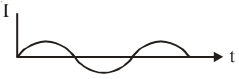
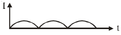
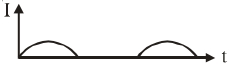
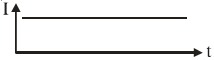
$A$ $p-n$ junction diode $(D)$ shown in the figure can act as a rectifier. An alternating current source $(V)$ is connected in the circuit. The current $(I)$ in the resistor $(R)$ can be shown by:
- A
- B
- C
- D
Explore More
Similar Questions
The output in the circuit shown in the figure is taken across a capacitor. The input signal is as shown in the figure.
Medium
View Solution$A$ full-wave rectifier circuit is operating from $50 \text{ Hz}$ mains. The fundamental frequency in the ripple output will be: (in $\text{ Hz}$)
If a full wave rectifier circuit is operating from $50 \,Hz$ mains, the fundamental frequency in the ripple will be (in $\,Hz$)
$A$ $PN$ junction diode is used as:
For a half-wave rectifier, the load resistance is $R_L = 2 \, k\Omega$ and the $P-N$ junction diode resistance is $R_d = 2 \, k\Omega$. The rectification efficiency is .... $\%$.
Difficult
View SolutionVedclass Products
For Students
Vedclass Test Series
Mock tests in real JEE/NEET style with performance analysis. 5-day free trial.
Start Free TrialFor Teachers
Exam Paper Generator
Generate Set A/B/C/D exam papers from 7.5L+ questions in 2 minutes. 3 chapters free.
Try FreeFor Institutes
Online Exam Module
Live online exams with unlimited students, 360° analytics & white-label branding.
See Demo