
A English
Application of junction diode (Rectifier) Questions in English
Class 12 Physics · Semiconductor Electronics · Application of junction diode (Rectifier)
129+
Questions
English
Language
100%
With Solutions
Showing 49 of 129 questions in English
1
EasyMCQ
The process by which $ac$ is converted into $dc$ is known as
A
Purification
B
Amplification
C
Rectification
D
Current amplification
Solution
(C) The process of converting alternating current $(ac)$ into direct current $(dc)$ is called $Rectification$. This process is typically performed using electronic components such as diodes,which allow current to flow in only one direction.
0 likes
View Solution2
EasyMCQ
The electrical circuit used to get smooth $dc$ output from a rectifier circuit is called
A
Oscillator
B
Filter
C
Amplifier
D
Logic gates
Solution
(B) rectifier circuit converts $ac$ into $dc$,but the output is pulsating in nature. To obtain a smooth $dc$ output,a filter circuit is used. $A$ filter circuit removes the $ac$ ripples from the rectified output. Common examples include capacitor filters,inductor filters,and $\pi$-filters.
0 likes
View Solution3
EasyMCQ
The $PN$ junction diode is used as:
A
An amplifier
B
$A$ rectifier
C
An oscillator
D
$A$ modulator
Solution
(B) $PN$ junction diode allows current to flow in only one direction (when forward-biased) and blocks it in the opposite direction (when reverse-biased). Due to this unidirectional property,it is primarily used as a rectifier to convert alternating current $(AC)$ into direct current $(DC)$.
0 likes
View Solution4
EasyMCQ
In comparison to a half-wave rectifier,the full-wave rectifier gives lower
A
Efficiency
B
Average dc
C
Average output voltage
D
None of these
Solution
(D) The efficiency of a half-wave rectifier is $40.6\%$,whereas the efficiency of a full-wave rectifier is $81.2\%$.
The average $DC$ output voltage for a half-wave rectifier is $V_{dc} = V_m / \pi$,while for a full-wave rectifier it is $V_{dc} = 2V_m / \pi$.
Since the full-wave rectifier has higher efficiency and a higher average output voltage compared to the half-wave rectifier,none of the given options are correct.
0 likes
View Solution5
EasyMCQ
The function of a rectifier is
A
To convert $ac$ into $dc$
B
To convert $dc$ into $ac$
C
Both $(a)$ and $(b)$
D
None of these
Solution
(A) rectifier is an electrical device that converts alternating current $(ac)$,which periodically reverses direction,into direct current $(dc)$,which flows in only one direction. This process is known as rectification. Therefore,the correct function is to convert $ac$ into $dc$.
0 likes
View Solution6
MediumMCQ
Which is the correct diagram of a half-wave rectifier?
A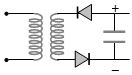
B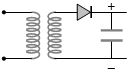
C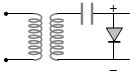
D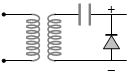
Solution
(B) half-wave rectifier uses a single diode to convert alternating current $(AC)$ into pulsating direct current $(DC)$.
In a half-wave rectifier circuit,the diode conducts only during the positive half-cycle of the input $AC$ signal and blocks the current during the negative half-cycle.
Diagram $B$ shows a transformer connected to a single diode in series with the load,which is the standard configuration for a half-wave rectifier.
Therefore,the correct diagram is $B$.
0 likes
View Solution7
EasyMCQ
The maximum efficiency of a full-wave rectifier is .........$\%$
A
$100$
B
$25.20$
C
$40.2$
D
$81.2$
Solution
(D) The efficiency $\eta$ of a full-wave rectifier is given by the formula: $\eta = \frac{81.2}{1 + \frac{r_f}{R_L}} \%$.
Here,$r_f$ is the forward resistance of the diode and $R_L$ is the load resistance.
For an ideal diode,the forward resistance $r_f$ is negligible compared to the load resistance $R_L$ (i.e.,$r_f \ll R_L$).
Therefore,the maximum efficiency is $\eta_{\max} = 81.2\%$.
Here,$r_f$ is the forward resistance of the diode and $R_L$ is the load resistance.
For an ideal diode,the forward resistance $r_f$ is negligible compared to the load resistance $R_L$ (i.e.,$r_f \ll R_L$).
Therefore,the maximum efficiency is $\eta_{\max} = 81.2\%$.
0 likes
View Solution8
EasyMCQ
If a full wave rectifier circuit is operating from $50\, Hz$ mains,the fundamental frequency in the ripple will be........$Hz$.
A
$50$
B
$70.7$
C
$100$
D
$25$
Solution
(C) In a full wave rectifier,the output consists of two pulses for every single cycle of the input $AC$ supply.
Since the input frequency is $f_{in} = 50\, Hz$,the output ripple frequency $f_{out}$ is given by the formula $f_{out} = 2 \times f_{in}$.
Substituting the given value: $f_{out} = 2 \times 50\, Hz = 100\, Hz$.
Therefore,the fundamental frequency in the ripple is $100\, Hz$.
Since the input frequency is $f_{in} = 50\, Hz$,the output ripple frequency $f_{out}$ is given by the formula $f_{out} = 2 \times f_{in}$.
Substituting the given value: $f_{out} = 2 \times 50\, Hz = 100\, Hz$.
Therefore,the fundamental frequency in the ripple is $100\, Hz$.
0 likes
View Solution9
EasyMCQ
In a full-wave rectifier,the input $AC$ current has a frequency '$v$'. The output frequency of the current is
A
$v/2$
B
$v$
C
$2v$
D
None of these
Solution
(C) In a full-wave rectifier,the circuit utilizes both halves of the input $AC$ cycle.
For every single cycle of the input $AC$ signal,the rectifier produces two pulses in the output.
Therefore,the frequency of the output signal is twice the frequency of the input signal.
Output frequency $= 2 \times$ Input frequency.
Given input frequency $= v$.
Thus,the output frequency $= 2v$.
For every single cycle of the input $AC$ signal,the rectifier produces two pulses in the output.
Therefore,the frequency of the output signal is twice the frequency of the input signal.
Output frequency $= 2 \times$ Input frequency.
Given input frequency $= v$.
Thus,the output frequency $= 2v$.
0 likes
View Solution10
EasyMCQ
$A$ diode is used as a/an
A
Oscillator
B
Amplifier
C
Rectifier
D
Modulator
Solution
(C) diode is a semiconductor device that allows current to flow in only one direction. Due to this unidirectional property,it is primarily used as a rectifier to convert alternating current $(AC)$ into direct current $(DC)$.
0 likes
View Solution11
EasyMCQ
The electrical circuits used to get smooth $d.c.$ output from a rectifier circuit are called:
A
Filter
B
Amplifier
C
Full wave rectifier
D
Oscillator
Solution
(A) rectifier circuit converts $a.c.$ into a pulsating $d.c.$ signal.
To obtain a smooth $d.c.$ output,we use a filter circuit.
$A$ filter circuit typically consists of components like capacitors and inductors that remove the ripples (fluctuations) from the pulsating $d.c.$ output of the rectifier.
Therefore,the correct answer is $A$ (Filter).
To obtain a smooth $d.c.$ output,we use a filter circuit.
$A$ filter circuit typically consists of components like capacitors and inductors that remove the ripples (fluctuations) from the pulsating $d.c.$ output of the rectifier.
Therefore,the correct answer is $A$ (Filter).
0 likes
View Solution12
MediumMCQ
The ripple factor in a half-wave rectifier is
A
$1.21$
B
$0.48$
C
$0.6$
D
None of these
Solution
(A) The ripple factor $r$ is defined as the ratio of the root mean square value of the ripple component to the direct current component of the output.
For a half-wave rectifier,the $rms$ value of the output current is $I_{rms} = I_0 / 2$ and the $dc$ value is $I_{dc} = I_0 / \pi$.
The formula for the ripple factor is $r = \sqrt{\left( \frac{I_{rms}}{I_{dc}} \right)^2 - 1}$.
Substituting the values: $r = \sqrt{\left( \frac{I_0 / 2}{I_0 / \pi} \right)^2 - 1} = \sqrt{\left( \frac{\pi}{2} \right)^2 - 1}$.
Since $\pi \approx 3.14$,$\pi / 2 \approx 1.57$.
$r = \sqrt{(1.57)^2 - 1} = \sqrt{2.46 - 1} = \sqrt{1.46} \approx 1.21$.
0 likes
View Solution13
EasyMCQ
Select the correct statement.
A
In a full wave rectifier,two diodes work alternately.
B
In a full wave rectifier,two diodes work simultaneously.
C
The efficiency of full wave and half wave rectifiers is same.
D
The full wave rectifier is bi-directional.
Solution
(A) full wave rectifier uses two diodes to convert both halves of the $AC$ input cycle into a unidirectional $DC$ output.
In a center-tapped full wave rectifier,the two diodes conduct during alternate half-cycles of the input $AC$ signal.
During the first half-cycle,one diode is forward-biased and conducts,while the other is reverse-biased.
During the second half-cycle,the roles are reversed.
Therefore,the two diodes work alternately to rectify the complete cycle.
0 likes
View Solution14
MediumMCQ
The peak voltage in the output of a half-wave diode rectifier fed with a sinusoidal signal without a filter is $10 \ V$. The $dc$ component of the output voltage is:
A
$10/\sqrt{2} \ V$
B
$10/\pi \ V$
C
$10 \ V$
D
$20/\pi \ V$
Solution
(B) For a half-wave rectifier,the output voltage is given by $V(t) = V_0 \sin(\omega t)$ for $0 \le t \le T/2$ and $V(t) = 0$ for $T/2 < t < T$.
The $dc$ component (average value) of the output voltage is calculated as:
$V_{dc} = \frac{1}{T} \int_{0}^{T} V(t) dt = \frac{1}{T} \int_{0}^{T/2} V_0 \sin(\omega t) dt$
Since $\omega = 2\pi/T$,we have:
$V_{dc} = \frac{V_0}{T} \left[ -\frac{\cos(\omega t)}{\omega} \right]_{0}^{T/2} = \frac{V_0}{T} \left( -\frac{1}{\omega} (\cos(\pi) - \cos(0)) \right) = \frac{V_0}{T} \left( \frac{2}{\omega} \right) = \frac{V_0}{T} \left( \frac{2}{2\pi/T} \right) = \frac{V_0}{\pi}$.
Given the peak voltage $V_0 = 10 \ V$,the $dc$ component is $V_{dc} = 10/\pi \ V$.
0 likes
View Solution15
MediumMCQ
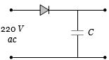
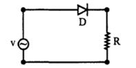
$A$ diode is connected to $220 \, V$ $(rms)$ $ac$ in series with a capacitor as shown in the figure. The voltage across the capacitor is..... $V$
A
$220$
B
$110$
C
$311.1$
D
$\frac{220}{\sqrt{2}}$
Solution
(C) The diode $D$ conducts during the positive half-cycle of the $ac$ supply because it is forward-biased. During the negative half-cycle,it is reverse-biased and does not conduct. The capacitor charges to the peak value of the input voltage during the positive half-cycle. The peak voltage $V_0$ is given by $V_0 = V_{rms} \times \sqrt{2} = 220\sqrt{2} \, V$. Since there is no load resistor to discharge the capacitor,it remains charged to the peak voltage $V_0 = 220\sqrt{2} \, V$. However,if we consider the average $DC$ output voltage for a half-wave rectifier,$V_{dc} = \frac{V_0}{\pi} = \frac{220\sqrt{2}}{\pi} \approx 99 \, V$. Given the options provided,the question likely refers to the peak voltage or a specific $RMS$ interpretation. Re-evaluating the standard interpretation for this specific textbook problem,the capacitor charges to the peak voltage $V_0 = 220\sqrt{2} \approx 311.1 \, V$. Thus,option $(C)$ is the correct answer.
0 likes
View Solution16
MediumMCQ
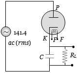
An alternating voltage of $141.4\,V$ (rms) is applied to a vacuum diode as shown in the figure. The maximum potential difference across the condenser will be......$V$
A
$100$
B
$200$
C
$100\sqrt{2}$
D
$200\sqrt{2}$
Solution
(B) The circuit shown is a half-wave rectifier circuit with a capacitor filter.
In a half-wave rectifier,the capacitor charges to the peak value of the input alternating voltage.
The relationship between the peak voltage $(V_{peak})$ and the root-mean-square voltage $(V_{rms})$ is given by:
$V_{peak} = \sqrt{2} \times V_{rms}$
Given that $V_{rms} = 141.4\,V$,we calculate the peak voltage as:
$V_{peak} = \sqrt{2} \times 141.4$
Since $\sqrt{2} \approx 1.414$,we have:
$V_{peak} = 1.414 \times 141.4 = 200\,V$
Therefore,the maximum potential difference across the condenser is $200\,V$.
0 likes
View Solution17
MediumMCQ
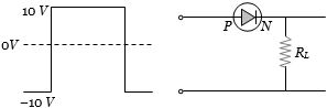
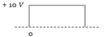
If the following input signal is sent through a $PN$-junction diode,then the output signal across $R_L$ will be:
A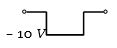
B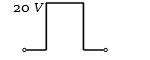
C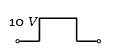
D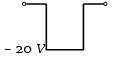
Solution
(C) The circuit acts as a half-wave rectifier.
When the input voltage is $+10 V$,the $P$-terminal of the diode is at a higher potential than the $N$-terminal,making the diode forward-biased. In this state,the diode conducts,and the output voltage across $R_L$ is $+10 V$.
When the input voltage is $-10 V$,the $P$-terminal is at a lower potential than the $N$-terminal,making the diode reverse-biased. In this state,the diode does not conduct,and the output voltage across $R_L$ is $0 V$.
Therefore,the output signal is a pulse that remains at $+10 V$ when the input is $+10 V$ and drops to $0 V$ when the input is $-10 V$.
0 likes
View Solution18
MediumMCQ
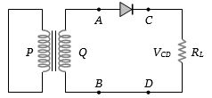
In the half-wave rectifier circuit shown,which one of the following waveforms is true for $V_{CD}$,the output across $C$ and $D$?
A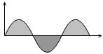
B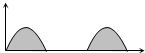
C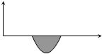
D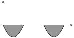
Solution
(B) half-wave rectifier uses a single diode to convert alternating current $(AC)$ into pulsating direct current $(DC)$.
It allows current to flow only during the positive half-cycle of the input $AC$ signal when the diode is forward-biased.
During the negative half-cycle,the diode is reverse-biased and blocks the current,resulting in zero output voltage across the load resistor $R_L$.
Therefore,the output waveform $V_{CD}$ consists of only the positive half-cycles of the input signal,with zero voltage during the negative half-cycles,which corresponds to the second waveform option.
0 likes
View Solution19
MediumMCQ
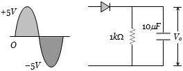
The output in the circuit shown in the figure is taken across a capacitor. The input signal is as shown in the figure.
A
B
C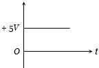
D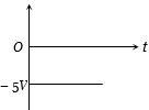
Solution
(D) The circuit acts as a half-wave rectifier with a filter capacitor.
During the positive half-cycle of the input,the diode is forward-biased,and the capacitor charges to the peak voltage of $5 \, V$.
During the negative half-cycle,the diode is reverse-biased and does not conduct.
The capacitor then discharges through the resistor $R$.
The time constant of the circuit is $\tau = RC = (1 \times 10^3 \, \Omega) \times (10 \times 10^{-6} \, F) = 0.01 \, s$.
Assuming the input frequency is standard (e.g.,$50 \, Hz$,period $T = 0.02 \, s$),the time constant $\tau$ is comparable to the period. However,in typical idealized problems of this type,the capacitor is assumed to hold its charge,resulting in a nearly constant $DC$ output voltage of $5 \, V$.
0 likes
View Solution20
MediumMCQ
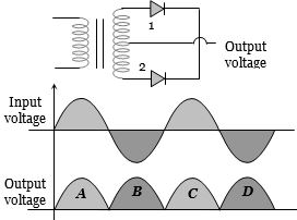
$A$ full-wave rectifier circuit along with the input and output voltage waveforms is shown in the figure. The contribution to the output voltage from diode $2$ is:
A
$A, C$
B
$B, D$
C
$B, C$
D
$A, D$
Solution
(B) In a full-wave rectifier circuit,during the positive half-cycle of the input $AC$ signal,diode $1$ is forward-biased and conducts,while diode $2$ is reverse-biased and does not conduct. Thus,the output pulses $A$ and $C$ are produced by diode $1$.
During the negative half-cycle of the input $AC$ signal,diode $2$ becomes forward-biased and conducts,while diode $1$ is reverse-biased. Thus,the output pulses $B$ and $D$ are produced by diode $2$.
Therefore,the contribution to the output voltage from diode $2$ corresponds to $B$ and $D$.
During the negative half-cycle of the input $AC$ signal,diode $2$ becomes forward-biased and conducts,while diode $1$ is reverse-biased. Thus,the output pulses $B$ and $D$ are produced by diode $2$.
Therefore,the contribution to the output voltage from diode $2$ corresponds to $B$ and $D$.
0 likes
View Solution21
MediumMCQ
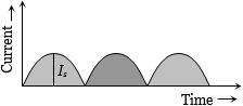
The output current versus time curve of a rectifier is shown in the figure. The average value of the output current in this case is
A
$0$
B
$i_0/\pi$
C
$2i_0/\pi$
D
$i_0$
Solution
(C) The given curve represents a full-wave rectified output current. The current $I$ varies as $I = I_0 \sin(\omega t)$ for the duration of each half-cycle.
To find the average value $(I_{avg})$ over one complete cycle of the rectified output (which has a period of $T/2 = \pi/\omega$),we integrate the current over one half-cycle and divide by the time interval:
$I_{avg} = \frac{1}{T/2} \int_0^{T/2} I_0 \sin(\omega t) dt$
$I_{avg} = \frac{\omega}{\pi} \int_0^{\pi/\omega} I_0 \sin(\omega t) dt$
$I_{avg} = \frac{\omega I_0}{\pi} \left[ -\frac{\cos(\omega t)}{\omega} \right]_0^{\pi/\omega}$
$I_{avg} = \frac{I_0}{\pi} [-\cos(\pi) + \cos(0)]$
$I_{avg} = \frac{I_0}{\pi} [1 + 1] = \frac{2I_0}{\pi}$
0 likes
View Solution22
MediumMCQ
In a diode $AM$ detector,the output circuit has $R = 1 \ k\Omega$ and $C = 10 \ pF$. Can it detect a carrier signal of $100 \ kHz$?
A
Yes
B
No
C
Data is insufficient
D
None of these
Solution
(B) For proper demodulation in an $AM$ detector,the time constant $RC$ must satisfy the condition: $\frac{1}{f_c} \ll RC < \frac{1}{f_m}$,where $f_c$ is the carrier frequency and $f_m$ is the message frequency.
First,calculate the period of the carrier signal: $\frac{1}{f_c} = \frac{1}{100 \times 10^3 \ Hz} = 10^{-5} \ s$.
Next,calculate the time constant of the circuit: $RC = (10^3 \ \Omega) \times (10 \times 10^{-12} \ F) = 10^{-8} \ s$.
Comparing the two,we see that $RC = 10^{-8} \ s$ is much smaller than $\frac{1}{f_c} = 10^{-5} \ s$.
Since the condition $\frac{1}{f_c} \ll RC$ is not satisfied,the circuit cannot effectively detect the $100 \ kHz$ carrier signal.
0 likes
View Solution23
MediumMCQ
In a rectifier circuit,the filter circuit:
A
Removes $AC$ components.
B
Removes $DC$ components.
C
Does not remove $AC$ components.
D
None of the above.
Solution
(A) rectifier converts $AC$ voltage into a pulsating $DC$ voltage. This pulsating $DC$ contains both $DC$ and $AC$ components (ripples). $A$ filter circuit,typically consisting of capacitors and inductors,is used to block or bypass the $AC$ ripples,thereby allowing only the $DC$ component to pass through to the load. Thus,the filter circuit removes $AC$ components from the rectified output.
0 likes
View Solution24
EasyMCQ
In a full-wave rectifier,the output is:
A
$AC$ voltage.
B
Pure $DC$ voltage.
C
Zero.
D
Unidirectional pulsating voltage.
Solution
(D) full-wave rectifier converts both halves of the input $AC$ cycle into a unidirectional output.
However,the output is not a steady $DC$ voltage like that from a battery.
It consists of a series of pulses that are always in the same direction,which is why it is referred to as a unidirectional pulsating voltage.
To obtain pure $DC$,a filter circuit is typically used after the rectifier.
However,the output is not a steady $DC$ voltage like that from a battery.
It consists of a series of pulses that are always in the same direction,which is why it is referred to as a unidirectional pulsating voltage.
To obtain pure $DC$,a filter circuit is typically used after the rectifier.
0 likes
View Solution25
EasyMCQ
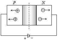
When $p$-type and $n$-type semiconductors are brought into contact,they form a $P-N$ junction which acts as a .........
A
Rectifier
B
Amplifier
C
Oscillator
D
Conductor
Solution
(A) $P-N$ junction diode allows current to flow in only one direction (forward bias) and blocks it in the opposite direction (reverse bias). This property of unidirectional conduction makes it suitable for converting alternating current $(AC)$ into direct current $(DC)$. This device is known as a rectifier.
0 likes
View Solution26
MediumMCQ
Which of the following figures represents a half-wave rectifier?
A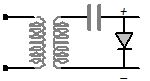
B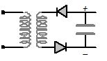
C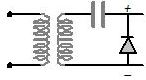
D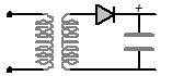
Solution
(D) half-wave rectifier uses a single diode in series with the load to convert $AC$ to $DC$.
In the provided options,the circuit in image $166-d103$ shows a transformer connected to a single diode in series with the load,which is the standard configuration for a half-wave rectifier.
Other options show either full-wave configurations or incorrect diode placements.
In the provided options,the circuit in image $166-d103$ shows a transformer connected to a single diode in series with the load,which is the standard configuration for a half-wave rectifier.
Other options show either full-wave configurations or incorrect diode placements.
0 likes
View Solution27
EasyMCQ
In a full-wave rectifier, if the input frequency is $50 \ Hz$, then the output ripple frequency is ......... $Hz$.
A
$50$
B
$100$
C
$200$
D
$25$
Solution
(B) In a full-wave rectifier, the circuit utilizes both halves of the input $AC$ cycle.
For each cycle of the input $AC$ signal, the output produces two pulses (one for the positive half-cycle and one for the negative half-cycle).
Therefore, the output frequency $(f_{out})$ is twice the input frequency $(f_{\in})$.
Given $f_{\in} = 50 \ Hz$.
$f_{out} = 2 \times f_{\in} = 2 \times 50 \ Hz = 100 \ Hz$.
0 likes
View Solution28
MediumMCQ
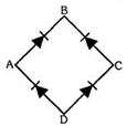
As shown in the figure,the input is applied between $A$ and $C$,and the output is taken between $B$ and $D$. What should the output be?
A
Zero
B
Same as input
C
Full-wave rectified
D
Half-wave rectified
Solution
(C) The given circuit is a bridge rectifier configuration.
When an $AC$ input is applied between terminals $A$ and $C$:
$1$. During the positive half-cycle,if $A$ is positive and $C$ is negative,the diodes connected to $A$ and $C$ will conduct such that current flows through the load connected between $B$ and $D$.
$2$. During the negative half-cycle,if $C$ is positive and $A$ is negative,the other pair of diodes will conduct,again ensuring that current flows through the load between $B$ and $D$ in the same direction.
Thus,the circuit acts as a full-wave rectifier,converting the $AC$ input into a pulsating $DC$ output across terminals $B$ and $D$.
0 likes
View Solution29
MediumMCQ
In a full-wave rectifier circuit, the input frequency is $50 \, Hz$. The fundamental frequency of the ripple is ....... $Hz$.
A
$50$
B
$25$
C
$100$
D
$70.7$
Solution
(C) In a full-wave rectifier, the output is obtained for both the positive and negative half-cycles of the input alternating current $(AC)$.
Since the output pulses twice for every single cycle of the input $AC$, the frequency of the ripple in the output is double the input frequency.
Given input frequency $f_{in} = 50 \, Hz$.
Therefore, the fundamental ripple frequency $f_{out} = 2 \times f_{in} = 2 \times 50 \, Hz = 100 \, Hz$.
Since the output pulses twice for every single cycle of the input $AC$, the frequency of the ripple in the output is double the input frequency.
Given input frequency $f_{in} = 50 \, Hz$.
Therefore, the fundamental ripple frequency $f_{out} = 2 \times f_{in} = 2 \times 50 \, Hz = 100 \, Hz$.
0 likes
View Solution30
MediumMCQ
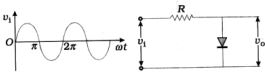
For the circuit shown in the figure,what will be the voltage waveform across the diode? Assume the diode is ideal.
A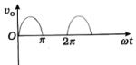
B
C
D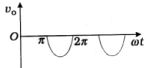
Solution
(D) During the positive half-cycle of the input voltage $(0 \leq \omega t \leq \pi)$,the diode is forward-biased. Since an ideal diode has zero resistance in forward bias,the voltage across it is zero.
During the negative half-cycle of the input voltage $(\pi \leq \omega t \leq 2\pi)$,the diode is reverse-biased and no current flows through it. Therefore,the input voltage appears across the diode.
Thus,the waveform shown in option $D$ will be obtained across the diode.
During the negative half-cycle of the input voltage $(\pi \leq \omega t \leq 2\pi)$,the diode is reverse-biased and no current flows through it. Therefore,the input voltage appears across the diode.
Thus,the waveform shown in option $D$ will be obtained across the diode.
0 likes
View Solution31
MediumMCQ
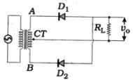
What will be the output waveform for the rectifier shown in the figure?
A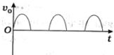
B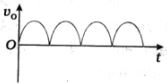
C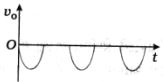
D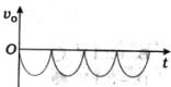
Solution
(D) The circuit shown is a full-wave rectifier. The anodes of both diodes $D_1$ and $D_2$ are connected to the transformer terminals $A$ and $B$ respectively,while the cathodes are connected together to one end of the load resistor $R_L$. The center tap $CT$ is connected to the other end of $R_L$.
When terminal $A$ is positive with respect to $CT$,diode $D_1$ is forward-biased,and current flows through $R_L$.
When terminal $B$ is positive with respect to $CT$,diode $D_2$ is forward-biased,and current flows through $R_L$ in the same direction.
However,in this specific circuit diagram,the diodes are oriented such that they conduct when the terminals $A$ and $B$ are negative with respect to $CT$. Thus,the current flows through $R_L$ in a direction that produces a negative voltage across it. Therefore,the output waveform shows full-wave rectification in the negative direction,which corresponds to option $D$.
0 likes
View Solution32
MediumMCQ
$A$ half-wave rectifier provides a load current of $1 \ k\Omega$. The input voltage is $220 \ V$. Neglecting the diode resistance,the values of average $DC$ voltage and average $DC$ current are respectively:
A
$90 \ V, 90 \ mA$
B
$85 \ V, 95 \ mA$
C
$99 \ V, 99 \ mA$
D
$75 \ V, 80 \ mA$
Solution
(C) For a half-wave rectifier,the peak voltage $V_m$ is given by $V_m = \sqrt{2} \times V_{rms}$.
Given $V_{rms} = 220 \ V$,so $V_m = 1.414 \times 220 \approx 311.13 \ V$.
The average $DC$ voltage $V_{dc}$ is given by $V_{dc} = \frac{V_m}{\pi}$.
$V_{dc} = \frac{311.13}{3.14} \approx 99.08 \ V \approx 99 \ V$.
The average $DC$ current $I_{dc}$ is given by $I_{dc} = \frac{V_{dc}}{R_L}$.
Given $R_L = 1 \ k\Omega = 1000 \ \Omega$.
$I_{dc} = \frac{99 \ V}{1000 \ \Omega} = 0.099 \ A = 99 \ mA$.
Thus,the average $DC$ voltage is $99 \ V$ and the average $DC$ current is $99 \ mA$.
0 likes
View Solution33
DifficultMCQ
For a half-wave rectifier, the load resistance is $R_L = 2 \, k\Omega$ and the $P-N$ junction diode resistance is $R_d = 2 \, k\Omega$. The rectification efficiency is .... $\%$.
A
$22.4$
B
$25.0$
C
$20.3$
D
$15.2$
Solution
(C) The efficiency of a half-wave rectifier is given by the formula: $\eta = 40.6 \left( \frac{R_L}{R_d + R_L} \right) \%$.
Given: $R_L = 2 \, k\Omega$ and $R_d = 2 \, k\Omega$.
Substituting the values into the formula:
$\eta = 40.6 \left( \frac{2 \, k\Omega}{2 \, k\Omega + 2 \, k\Omega} \right) \%$.
$\eta = 40.6 \left( \frac{2}{4} \right) \%$.
$\eta = 40.6 \times 0.5 = 20.3 \%$.
Thus, the rectification efficiency is $20.3 \%$.
0 likes
View Solution34
MediumMCQ
If a square signal of $10 \ V$ (varying from $+5 \ V$ to $-5 \ V$) is applied to a $P-N$ junction diode as shown,the output signal across $R_L$ will be:
A
B
C
D
Solution
(A) The circuit consists of a $P-N$ junction diode in series with a load resistor $R_L$.
When the input signal is positive $(+5 \ V)$,the diode is forward-biased and acts as a closed switch (assuming an ideal diode). Thus,the entire input voltage appears across the load resistor $R_L$.
When the input signal is negative $(-5 \ V)$,the diode is reverse-biased and acts as an open switch. Thus,no current flows through $R_L$,and the output voltage across $R_L$ is $0 \ V$.
Therefore,the output signal is a square wave that varies between $0 \ V$ and $+5 \ V$.
0 likes
View Solution35
EasyMCQ
When a sinusoidal $AC$ voltage is applied to a half-wave rectifier,the peak output voltage is $10 \ V$. The value of the $DC$ voltage in this output is .......
A
$10 \sqrt{2} \ V$
B
$\frac{10}{\pi} \ V$
C
$10 \ V$
D
$\frac{20}{\pi} \ V$
Solution
(B) For a half-wave rectifier,the average or $DC$ output voltage $(V_{DC})$ is given by the formula:
$V_{DC} = \frac{V_m}{\pi}$
where $V_m$ is the peak (maximum) output voltage.
Given that $V_m = 10 \ V$,
$V_{DC} = \frac{10}{\pi} \ V$.
$V_{DC} = \frac{V_m}{\pi}$
where $V_m$ is the peak (maximum) output voltage.
Given that $V_m = 10 \ V$,
$V_{DC} = \frac{10}{\pi} \ V$.
0 likes
View Solution36
EasyMCQ
Which of the following circuits represents a full-wave rectifier?
A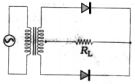
B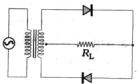
C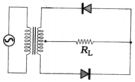
D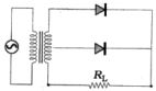
Solution
(A) full-wave rectifier circuit uses a center-tapped transformer and two diodes. The two diodes are connected to the two ends of the secondary coil of the transformer. The load resistor $R_L$ is connected between the center tap of the secondary coil and the common junction of the two diodes. During the first half cycle of the $AC$ input,one diode is forward-biased and conducts,while the other is reverse-biased. During the second half cycle,the roles are reversed. This ensures that current flows through the load resistor $R_L$ in the same direction during both half cycles. Option $A$ correctly depicts this configuration.
0 likes
View Solution37
MediumMCQ
The $P-N$ junction diode acts as a rectifier in the circuit shown below. An alternating current source is connected to the circuit. The current in the resistor $(R)$ can be observed as follows. Which of the following is correct?
A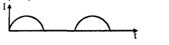
B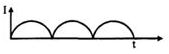
C
D
Solution
(C) The circuit shown is a half-wave rectifier circuit.
During the positive half-cycle of the input $AC$ voltage,the diode is forward-biased and conducts current through the resistor $R$.
During the negative half-cycle of the input $AC$ voltage,the diode is reverse-biased and does not conduct,so the current through the resistor $R$ is zero.
Therefore,the output current waveform across the resistor $R$ consists of only the positive half-cycles,which corresponds to the waveform shown in option $C$.
0 likes
View Solution38
DifficultMCQ
In a full-wave $P-N$ junction diode rectifier, a load resistance of $1500 \ \Omega$ is used. No filter is used. Assume each diode has a forward resistance $R_f = 10 \ \Omega$ and reverse resistance $R_r = \infty$. When a sinusoidal voltage with a peak amplitude of $30 \ V$ and frequency $50 \ Hz$ is applied, calculate the $D.C.$ power output and $A.C.$ power input respectively.
A
$255.5 \ mW, 155.8 \ mW$
B
$262.1 \ mW, 155.8 \ mW$
C
$275.3 \ mW, 205.5 \ mW$
D
$240.4 \ mW, 295.9 \ mW$
Solution
$(D)$ The peak current $I_m$ is given by $I_m = \frac{V_m}{R_f + R_L} = \frac{30}{10 + 1500} = \frac{30}{1510} \approx 0.01987 \ A = 19.87 \ mA$.
The $D.C.$ load current is $I_{dc} = \frac{2I_m}{\pi} = \frac{2 \times 19.87 \ mA}{3.1416} \approx 12.65 \ mA$.
The $D.C.$ power output is $P_{dc} = I_{dc}^2 \times R_L = (12.65 \times 10^{-3})^2 \times 1500 \approx 240.1 \ mW$.
The $R.M.S.$ current for a full-wave rectifier is $I_{rms} = \frac{I_m}{\sqrt{2}} = \frac{19.87}{\sqrt{2}} \approx 14.05 \ mA$.
The $A.C.$ power input is $P_{in} = I_{rms}^2 \times (R_f + R_L) = (14.05 \times 10^{-3})^2 \times (10 + 1500) = 1.974 \times 10^{-4} \times 1510 \approx 298.1 \ mW$.
Comparing with the given options, the closest values are $240.4 \ mW$ and $295.9 \ mW$.
0 likes
View Solution39
MediumMCQ
In a full-wave $P-N$ junction diode rectifier,a load resistance of $1500 \ \Omega$ is used. No filter is used. Assume each diode has a forward resistance $R_f = 10 \ \Omega$ and a reverse resistance $R_f = \infty$. When an input voltage with an amplitude of $30 \ V$ and a frequency of $50 \ Hz$ is applied,what are the peak,average,and $RMS$ values of the load current,respectively?
A
$20.75 \ mA, 7.88 \ mA, 12.3 \ mA$
B
$19.9 \ mA, 12.66 \ mA, 14.08 \ mA$
C
$24.75 \ mA, 12.3 \ mA, 12.3 \ mA$
D
$19.05 \ mA, 6.88 \ mA, 10.3 \ mA$
Solution
(B) The peak current $I_m$ is given by $I_m = \frac{V_m}{R_f + R_L}$.
Given $V_m = 30 \ V$,$R_f = 10 \ \Omega$,and $R_L = 1500 \ \Omega$:
$I_m = \frac{30}{10 + 1500} = \frac{30}{1510} \approx 0.019868 \ A \approx 19.9 \ mA$.
For a full-wave rectifier,the average $(DC)$ current $I_{dc}$ is given by $I_{dc} = \frac{2 I_m}{\pi}$.
$I_{dc} = \frac{2 \times 19.9 \ mA}{3.14159} \approx 12.66 \ mA$.
The $RMS$ current $I_{rms}$ for a full-wave rectifier is given by $I_{rms} = \frac{I_m}{\sqrt{2}}$.
$I_{rms} = \frac{19.9 \ mA}{1.414} \approx 14.08 \ mA$.
Thus,the values are $19.9 \ mA, 12.66 \ mA, 14.08 \ mA$.
0 likes
View Solution40
MediumMCQ
In a half-wave rectifier using a $PN$ junction diode,the input voltage has an amplitude of $25 \ V$ and a frequency of $50 \ Hz$. No filter is used,and the load resistance is $1000 \ \Omega$. The forward resistance of the diode is $10 \ \Omega$. Calculate the peak,average,and $rms$ values of the load current,respectively.
A
$24.75 \ mA, 7.88 \ mA, 12.38 \ mA$
B
$20.75 \ mA, 7.15 \ mA, 11.3 \ mA$
C
$24.75 \ mA, 12.3 \ mA, 12.3 \ mA$
D
$20.05 \ mA, 6.88 \ mA, 10.3 \ mA$
Solution
(A) The peak current $I_m$ is given by $I_m = \frac{V_m}{R_f + R_L} = \frac{25}{10 + 1000} = \frac{25}{1010} \approx 24.75 \ mA$.
The average current $I_{dc}$ for a half-wave rectifier is $I_{dc} = \frac{I_m}{\pi} = \frac{24.75}{3.14} \approx 7.88 \ mA$.
The $rms$ current $I_{rms}$ for a half-wave rectifier is $I_{rms} = \frac{I_m}{2} = \frac{24.75}{2} = 12.375 \ mA \approx 12.38 \ mA$.
The average current $I_{dc}$ for a half-wave rectifier is $I_{dc} = \frac{I_m}{\pi} = \frac{24.75}{3.14} \approx 7.88 \ mA$.
The $rms$ current $I_{rms}$ for a half-wave rectifier is $I_{rms} = \frac{I_m}{2} = \frac{24.75}{2} = 12.375 \ mA \approx 12.38 \ mA$.
0 likes
View Solution41
DifficultMCQ
$A$ full-wave rectifier provides a load of $1 \ k\Omega$. The diode is supplied with an $a.c.$ voltage of $220 \ V_{rms}$. If the diode resistance is neglected,the average $d.c.$ voltage and average $d.c.$ current are respectively:
A
$190 \ V, 190 \ mA$
B
$185 \ V, 195 \ mA$
C
$198 \ V, 198 \ mA$
D
$175 \ V, 180 \ mA$
Solution
(C) For a full-wave rectifier,the average $d.c.$ voltage is given by $V_{dc} = \frac{2V_m}{\pi} \approx 0.636 V_m$,where $V_m$ is the peak voltage of each secondary half-cycle.
Given the $rms$ voltage $V = 220 \ V$,the peak voltage is $V_m = V\sqrt{2} = 220\sqrt{2} \approx 311.13 \ V$.
Substituting this into the formula: $V_{dc} = 0.636 \times 311.13 \approx 198 \ V$.
Alternatively,$V_{dc} = \frac{2 \times (V\sqrt{2})}{\pi} = \frac{2\sqrt{2}}{\pi} V \approx 0.9 \times 220 = 198 \ V$.
The average $d.c.$ current is $I_{dc} = \frac{V_{dc}}{R_L} = \frac{198 \ V}{1000 \ \Omega} = 0.198 \ A = 198 \ mA$.
0 likes
View Solution42
DifficultMCQ
$A$ full-wave rectifier supplies a load of $1 \ k\Omega$. The $a.c.$ voltage applied to the diode is $220 \ V_{rms}$. If the diode resistance is neglected,the value of the ripple voltage $(rms)$ is .... $V$.
A
$90$
B
$101.85$
C
$99.99$
D
$95.43$
Solution
(D) For a full-wave rectifier,the peak voltage $V_m$ is given by $V_m = V_{rms} \times \sqrt{2}$.
Given $V_{rms} = 220 \ V$,so $V_m = 220 \times 1.414 = 311.13 \ V$.
The average $d.c.$ voltage is $V_{dc} = \frac{2V_m}{\pi} = 0.6366 \times 311.13 \approx 198.07 \ V$.
The ripple factor $r$ for a full-wave rectifier is $0.482$.
The ripple voltage $(rms)$ is given by $V_{r(rms)} = r \times V_{dc}$.
$V_{r(rms)} = 0.482 \times 198.07 \approx 95.47 \ V$.
Rounding to the nearest option,the value is $95.43 \ V$.
0 likes
View Solution43
DifficultMCQ
In a half-wave rectifier using a $PN$ junction diode,the input voltage has an amplitude of $25 \ V$ and a frequency of $50 \ Hz$. No filter is used,and the load resistance is $1000 \ \Omega$. The forward resistance of the diode is $10 \ \Omega$. The ripple factor is:
A
$0.15$
B
$1.5$
C
$1.21$
D
$1.73$
Solution
(C) The peak current $I_m$ is given by $I_m = \frac{V_m}{R_f + R_L} = \frac{25}{10 + 1000} = \frac{25}{1010} \approx 0.02475 \ A = 24.75 \ mA$.
The $DC$ current $I_{dc}$ is $I_{dc} = \frac{I_m}{\pi} = \frac{24.75}{\pi} \approx 7.88 \ mA$.
The $RMS$ current $I_{rms}$ for a half-wave rectifier is $I_{rms} = \frac{I_m}{2} = \frac{24.75}{2} = 12.375 \ mA$.
The ripple factor $\gamma$ is defined as $\gamma = \sqrt{\left( \frac{I_{rms}}{I_{dc}} \right)^2 - 1}$.
Substituting the values: $\gamma = \sqrt{\left( \frac{12.375}{7.88} \right)^2 - 1} = \sqrt{(1.57)^2 - 1} = \sqrt{2.46 - 1} = \sqrt{1.46} \approx 1.21$.
0 likes
View Solution44
MediumMCQ
$A$ half-wave rectifier provides a load current of $1 \ k\Omega$. The input voltage is $220 \ V$. Neglecting the diode resistance,the value of the ripple voltage $(rms)$ is .... $V$.
A
$90$
B
$101.85$
C
$99.99$
D
$119.79$
Solution
(D) For a half-wave rectifier,the peak voltage is $V_m = \sqrt{2} \times V_{rms} = \sqrt{2} \times 220 \approx 311.13 \ V$.
The $DC$ output voltage is $V_{dc} = \frac{V_m}{\pi} = \frac{311.13}{3.14} \approx 99 \ V$.
The ripple factor $r$ for a half-wave rectifier is $1.21$.
The ripple voltage $(rms)$ is given by $(V_r)_{rms} = r \times V_{dc}$.
Substituting the values: $(V_r)_{rms} = 1.21 \times 99 = 119.79 \ V$.
The $DC$ output voltage is $V_{dc} = \frac{V_m}{\pi} = \frac{311.13}{3.14} \approx 99 \ V$.
The ripple factor $r$ for a half-wave rectifier is $1.21$.
The ripple voltage $(rms)$ is given by $(V_r)_{rms} = r \times V_{dc}$.
Substituting the values: $(V_r)_{rms} = 1.21 \times 99 = 119.79 \ V$.
0 likes
View Solution45
DifficultMCQ
In a half-wave rectifier using a $PN$ junction diode,the input voltage has an amplitude of $25 \ V$ and a frequency of $50 \ Hz$. No filter is used,and the load resistance is $1000 \ \Omega$. The forward resistance of the diode is $10 \ \Omega$. The $d.c.$ power output and $a.c.$ power input are respectively:
A
$55 \ mW, 155 \ mW$
B
$62 \ mW, 155 \ mW$
C
$75 \ mW, 205 \ mW$
D
$70 \ mW, 170 \ mW$
Solution
(B) The peak current $I_m$ is given by $I_m = \frac{V_m}{R_f + R_L} = \frac{25}{10 + 1000} = 24.75 \ mA$.
The $d.c.$ current is $I_{dc} = \frac{I_m}{\pi} = \frac{24.75}{3.14} \approx 7.88 \ mA$.
The $r.m.s.$ current is $I_{rms} = \frac{I_m}{2} = \frac{24.75}{2} = 12.38 \ mA$.
The $d.c.$ power output is $P_{dc} = I_{dc}^2 \times R_L = (7.88 \times 10^{-3})^2 \times 1000 \approx 62 \ mW$.
The $a.c.$ power input is $P_{ac} = I_{rms}^2 \times (R_f + R_L) = (12.38 \times 10^{-3})^2 \times (10 + 1000) \approx 155 \ mW$.
0 likes
View Solution46
DifficultMCQ
In a half-wave rectifier using a $PN$ junction diode, the input voltage has an amplitude of $25 \ V$ and a frequency of $50 \ Hz$. No filter is used, and the load resistance is $1000 \ \Omega$. The forward resistance of the diode is $10 \ \Omega$. The efficiency of the rectifier is approximately ...... $\%$.
A
$10$
B
$20$
C
$30$
D
$40$
Solution
(D) The peak current $I_m$ is given by $I_m = \frac{V_m}{R_f + R_L} = \frac{25}{10 + 1000} = \frac{25}{1010} \approx 0.02475 \ A = 24.75 \ mA$.
The $DC$ current is $I_{dc} = \frac{I_m}{\pi} = \frac{24.75}{\pi} \approx 7.88 \ mA$.
The $RMS$ current is $I_{rms} = \frac{I_m}{2} = \frac{24.75}{2} = 12.375 \ mA$.
The $DC$ output power is $P_{dc} = I_{dc}^2 \times R_L = (7.88 \times 10^{-3})^2 \times 1000 \approx 0.0621 \ W = 62.1 \ mW$.
The $AC$ input power is $P_{ac} = I_{rms}^2 \times (R_f + R_L) = (12.375 \times 10^{-3})^2 \times (10 + 1000) \approx 0.1547 \ W = 154.7 \ mW$.
The efficiency $\eta$ is given by $\eta = \frac{P_{dc}}{P_{ac}} \times 100 = \frac{62.1}{154.7} \times 100 \approx 40.14 \ \%$.
Thus, the efficiency is approximately $40 \ \%$.
0 likes
View Solution47
MediumMCQ
For a half-wave rectifier,if the maximum output voltage is $10 \ V$,what will be the $D.C.$ output voltage?
A
$20/\pi \ V$
B
$10/\sqrt{2} \ V$
C
$10/\pi \ V$
D
$10 \ V$
Solution
(C) For a half-wave rectifier,the average or $D.C.$ output voltage $(V_{dc})$ is given by the formula:
$V_{dc} = \frac{V_0}{\pi}$
where $V_0$ is the peak or maximum output voltage.
Given that $V_0 = 10 \ V$,we substitute this value into the formula:
$V_{dc} = \frac{10}{\pi} \ V$
Therefore,the $D.C.$ output voltage is $10/\pi \ V$.
$V_{dc} = \frac{V_0}{\pi}$
where $V_0$ is the peak or maximum output voltage.
Given that $V_0 = 10 \ V$,we substitute this value into the formula:
$V_{dc} = \frac{10}{\pi} \ V$
Therefore,the $D.C.$ output voltage is $10/\pi \ V$.
0 likes
View Solution48
MediumMCQ
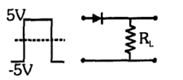
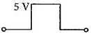
If in a $p-n$ junction circuit,a square input signal of $5\,V$ is applied as shown,then the output across $R_L$ will be:

A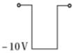
B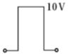
C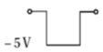
D
Solution
(D) The given circuit is a half-wave rectifier circuit.
When the input signal is positive $(+5\,V)$,the diode is in forward bias and acts as a closed switch. Thus,the output voltage across $R_L$ is equal to the input voltage,which is $5\,V$.
When the input signal is negative $(-5\,V)$,the diode is in reverse bias and acts as an open switch. Thus,no current flows through $R_L$,and the output voltage across $R_L$ is $0\,V$.
Therefore,the output across $R_L$ will be a square wave with a peak voltage of $5\,V$ during the positive half-cycle and $0\,V$ during the negative half-cycle.
0 likes
View Solution49
DifficultMCQ
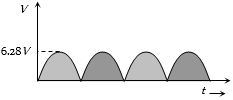
For the given electric voltage signal,the $dc$ value is......$V$.
A
$6.28$
B
$3.14$
C
$4$
D
$0$
Solution
(C) The given waveform represents a full-wave rectified signal.
For a full-wave rectified signal,the average or $dc$ value is given by the formula:
$V_{dc} = \frac{2V_0}{\pi}$
From the graph,the peak voltage $V_0 = 6.28 \ V$.
Substituting the values:
$V_{dc} = \frac{2 \times 6.28}{3.14}$
$V_{dc} = 2 \times 2 = 4 \ V$.
Therefore,the correct option is $C$.
For a full-wave rectified signal,the average or $dc$ value is given by the formula:
$V_{dc} = \frac{2V_0}{\pi}$
From the graph,the peak voltage $V_0 = 6.28 \ V$.
Substituting the values:
$V_{dc} = \frac{2 \times 6.28}{3.14}$
$V_{dc} = 2 \times 2 = 4 \ V$.
Therefore,the correct option is $C$.
0 likes
View SolutionSemiconductor Electronics — Application of junction diode (Rectifier) · Frequently Asked Questions
1Are these Semiconductor Electronics questions useful for JEE and NEET?
Yes. All questions in this section are mapped to JEE Main and NEET exam patterns. Previous year questions from JEE Main, NEET, GUJCET and state-level exams are included with full solutions.
2Can I switch to Hindi or Gujarati for these questions?
Yes. Use the language tabs in the hero section or the sidebar to view the same questions and solutions in English, Hindi or Gujarati.
3How do I generate a question paper from this subtopic?
Use the Vedclass Exam Paper Generator — select the chapter and subtopic, set difficulty, and generate Sets A, B, C, D automatically. First 3 chapters of every subject are free.
Vedclass Products
For Students
Vedclass Test Series
Mock tests in real JEE/NEET style with performance analysis. 5-day free trial.
Start Free TrialFor Teachers
Exam Paper Generator
Generate Set A/B/C/D papers from this chapter in 2 minutes. 3 chapters free.
Try FreeFor Institutes
Online Exam Module
Live online exams with unlimited students, 360° analytics & white-label branding.
See DemoFor Teachers & Institutes
Generate a Semiconductor Electronics Exam Paper in 2 Minutes
Select subtopic & difficulty — Sets A, B, C, D auto-generated with No Repeat logic.
First 3 chapters of every subject are free — no payment required.