
A English
PN Junction and Diode Questions in English
Class 12 Physics · Semiconductor Electronics · PN Junction and Diode
404+
Questions
English
Language
100%
With Solutions
Showing 48 of 404 questions in English
101
EasyMCQ
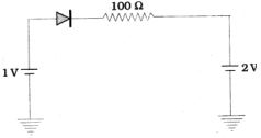
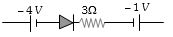
In the given circuit,the current flowing through the ideal $P-N$ junction diode is .......$mA$.
A
$0$
B
$1$
C
$10$
D
$30$
Solution
(A) In the given circuit,the $P$-terminal of the diode is connected to $1 \ V$ and the $N$-terminal is connected to $2 \ V$ through a $100 \ \Omega$ resistor.
Since the potential at the $N$-terminal $(2 \ V)$ is higher than the potential at the $P$-terminal $(1 \ V)$,the diode is in reverse bias.
An ideal diode in reverse bias acts as an open circuit (infinite resistance).
Therefore,no current flows through the circuit.
Hence,the current $I = 0 \ mA$.
Since the potential at the $N$-terminal $(2 \ V)$ is higher than the potential at the $P$-terminal $(1 \ V)$,the diode is in reverse bias.
An ideal diode in reverse bias acts as an open circuit (infinite resistance).
Therefore,no current flows through the circuit.
Hence,the current $I = 0 \ mA$.
0 likes
View Solution102
DifficultMCQ
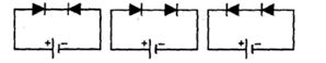
Two identical $P-N$ junctions are connected in series with a battery in three ways as shown in the figure. In which two circuits will the potential difference across the $P-N$ junctions be equal?
A
In circuits $1$ and $2$
B
In circuits $2$ and $3$
C
In circuits $3$ and $1$
D
In circuit $1$ only
Solution
(B) In circuit $1$,the two diodes are connected in opposite directions (one forward biased,one reverse biased). The reverse biased diode acts as a high resistance,so almost the entire battery voltage appears across it.
In circuit $2$,both diodes are forward biased. They share the battery voltage equally,so each has a potential difference of $V/2$.
In circuit $3$,both diodes are reverse biased. They share the battery voltage equally,so each has a potential difference of $V/2$.
Since the potential difference across each diode in circuit $2$ and circuit $3$ is $V/2$,the potential difference is equal in circuits $2$ and $3$.
0 likes
View Solution103
MediumMCQ
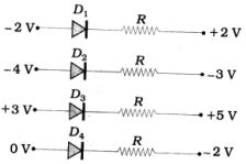
In the given circuits,which diode is in forward bias?
A
$D_1$
B
$D_2$
C
$D_3$
D
$D_4$
Solution
(D) diode is in forward bias if the potential at the $p$-side $(V_p)$ is higher than the potential at the $n$-side $(V_n)$.
For $D_1$: $V_p = -2 \ V$,$V_n = +2 \ V$. Since $V_p < V_n$,it is reverse biased.
For $D_2$: $V_p = -4 \ V$,$V_n = -3 \ V$. Since $V_p < V_n$,it is reverse biased.
For $D_3$: $V_p = +3 \ V$,$V_n = +5 \ V$. Since $V_p < V_n$,it is reverse biased.
For $D_4$: $V_p = 0 \ V$,$V_n = -2 \ V$. Since $V_p > V_n$,it is forward biased.
Therefore,diode $D_4$ is in forward bias.
0 likes
View Solution104
MediumMCQ
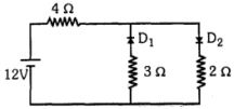
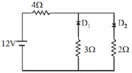
In the given circuit,two ideal diodes are connected in parallel in opposite directions. What is the current $I$ flowing in the circuit (in $A$)?
A
$1.71$
B
$2$
C
$2.31$
D
$1.33$
Solution
(B) In the given circuit,the diode $D_1$ is in reverse bias,so it acts as an open circuit (infinite resistance). The diode $D_2$ is in forward bias,so it acts as a short circuit (zero resistance).
Applying Kirchhoff's voltage law to the loop containing the battery,the $4 \ \Omega$ resistor,and the branch with $D_2$ and the $2 \ \Omega$ resistor:
$12 \ V - I(4 \ \Omega) - I(2 \ \Omega) = 0$
$12 - 6I = 0$
$6I = 12$
$I = 2 \ A$
Applying Kirchhoff's voltage law to the loop containing the battery,the $4 \ \Omega$ resistor,and the branch with $D_2$ and the $2 \ \Omega$ resistor:
$12 \ V - I(4 \ \Omega) - I(2 \ \Omega) = 0$
$12 - 6I = 0$
$6I = 12$
$I = 2 \ A$
0 likes
View Solution105
EasyMCQ
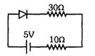
In the given circuit,the current is $0.1 \ A$. The resistance of the $P-N$ junction is .... $\Omega$.
A
$10$
B
$20$
C
$18$
D
$12$
Solution
(A) Let the resistance of the $P-N$ junction be $R$.
According to Ohm's law for the series circuit:
$I = \frac{V}{R_{total}}$
$0.1 = \frac{5}{R + 30 + 10}$
$0.1 = \frac{5}{R + 40}$
$R + 40 = \frac{5}{0.1}$
$R + 40 = 50$
$R = 50 - 40 = 10 \ \Omega$
Thus,the resistance of the $P-N$ junction is $10 \ \Omega$.
According to Ohm's law for the series circuit:
$I = \frac{V}{R_{total}}$
$0.1 = \frac{5}{R + 30 + 10}$
$0.1 = \frac{5}{R + 40}$
$R + 40 = \frac{5}{0.1}$
$R + 40 = 50$
$R = 50 - 40 = 10 \ \Omega$
Thus,the resistance of the $P-N$ junction is $10 \ \Omega$.
0 likes
View Solution106
MediumMCQ
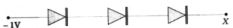
In the given figure,three silicon diodes are connected in series. What voltage at point $X$ will make all three diodes forward-biased?
A
$0 \ V$
B
$+2.1 \ V$
C
$-2.1 \ V$
D
$-3.1 \ V$
Solution
(D) For a silicon diode,the barrier potential is approximately $0.7 \ V$.
Since there are three silicon diodes connected in series,the total voltage drop required to forward-bias all of them is $V_{total} = 3 \times 0.7 \ V = 2.1 \ V$.
For the diodes to be forward-biased,the anode potential must be higher than the cathode potential by at least $2.1 \ V$.
Let the potential at point $X$ be $V_X$. The anode is connected to $-1 \ V$ and the cathode is at point $X$.
For forward bias,$V_{anode} - V_{cathode} \geq 2.1 \ V$.
$-1 \ V - V_X = 2.1 \ V$.
$V_X = -1 \ V - 2.1 \ V = -3.1 \ V$.
Thus,the potential at point $X$ must be $-3.1 \ V$.
0 likes
View Solution107
EasyMCQ
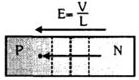
Suppose the thickness of the depletion layer in a $P-N$ junction is $10^{-6} \ m$ and the value of the depletion barrier is $0.1 \ V$. Then the electric field is ....... $V \ m^{-1}$.
A
$10^7$
B
$10^{-6}$
C
$10^5$
D
$10^{-5}$
Solution
(C) Given:
Thickness of the depletion layer,$d = 10^{-6} \ m$
Depletion barrier potential,$V = 0.1 \ V$
The relationship between the electric field $E$,potential $V$,and distance $d$ is given by $V = E \times d$.
Therefore,$E = \frac{V}{d}$.
Substituting the values:
$E = \frac{0.1}{10^{-6}} = 0.1 \times 10^6 = 10^5 \ V \ m^{-1}$.
Thus,the electric field is $10^5 \ V \ m^{-1}$.
0 likes
View Solution108
MediumMCQ
In a $P-N$ junction,the thickness of the depletion layer is $10^{-6} \ m$ and the potential barrier is $0.1 \ V$. The electric field in $V/m$ is:
A
$10^7$
B
$10^{-6}$
C
$10^5$
D
$10^{-5}$
Solution
(C) The electric field $E$ in a depletion layer is given by the formula $E = \frac{V}{d}$,where $V$ is the potential barrier and $d$ is the thickness of the depletion layer.
Given: $V = 0.1 \ V$ and $d = 10^{-6} \ m$.
Substituting the values: $E = \frac{0.1}{10^{-6}} = 0.1 \times 10^6 = 10^5 \ V/m$.
Therefore,the electric field is $10^5 \ V/m$.
Given: $V = 0.1 \ V$ and $d = 10^{-6} \ m$.
Substituting the values: $E = \frac{0.1}{10^{-6}} = 0.1 \times 10^6 = 10^5 \ V/m$.
Therefore,the electric field is $10^5 \ V/m$.
0 likes
View Solution109
MediumMCQ
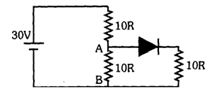
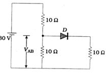
For the given circuit,find $V_{AB} = ......V$.
A
$10$
B
$20$
C
$30$
D
None of these
Solution
(A) The diode is in forward bias because the potential at point $A$ is higher than the potential at point $B$.
The diode and the $10R$ resistor in parallel with the lower $10R$ resistor form an equivalent resistance of $R_{eq} = \frac{10R \times 10R}{10R + 10R} = 5R$.
Now,the circuit acts as a voltage divider with a $10R$ resistor in series with the equivalent $5R$ resistance.
The voltage $V_{AB}$ across the parallel combination is given by the voltage divider rule:
$V_{AB} = \left( \frac{5R}{10R + 5R} \right) \times 30V$
$V_{AB} = \left( \frac{5R}{15R} \right) \times 30V$
$V_{AB} = \frac{1}{3} \times 30V = 10V$.
0 likes
View Solution110
MediumMCQ
The ratio of forward bias resistance to reverse bias resistance of a $P-N$ junction is approximately .......
A
$10^{-1} : 1$
B
$10^{-2} : 1$
C
$10^{-3} : 1$
D
$10^{-4} : 1$
Solution
(D) In forward bias,the resistance of a $P-N$ junction $(r_{fb})$ is typically of the order of $10^2 \ \Omega$ (approx $100 \ \Omega$).
In reverse bias,the resistance of a $P-N$ junction $(r_{rb})$ is typically of the order of $10^6 \ \Omega$.
Therefore,the ratio of forward bias resistance to reverse bias resistance is:
$\frac{r_{fb}}{r_{rb}} = \frac{10^2}{10^6} = 10^{-4} : 1$.
In reverse bias,the resistance of a $P-N$ junction $(r_{rb})$ is typically of the order of $10^6 \ \Omega$.
Therefore,the ratio of forward bias resistance to reverse bias resistance is:
$\frac{r_{fb}}{r_{rb}} = \frac{10^2}{10^6} = 10^{-4} : 1$.
0 likes
View Solution111
EasyMCQ
Which of the following diodes is reverse biased?
A
B
C
D
Solution
(A, B, D) diode is reverse biased when the potential at its cathode $(V_K)$ is higher than the potential at its anode $(V_A)$,i.e.,$V_K > V_A$.
Let us analyze each option:
$A$: $V_A = +5V$,$V_K = +10V$. Since $V_K > V_A$,it is reverse biased.
$B$: $V_A = -12V$,$V_K = -10V$. Since $V_K > V_A$,it is reverse biased.
$C$: $V_A = 0V$,$V_K = -10V$. Since $V_A > V_K$,it is forward biased.
$D$: $V_A = 0V$,$V_K = +5V$. Since $V_K > V_A$,it is reverse biased.
Note: In many standard textbook problems of this type,multiple options might satisfy the condition. Based on the provided image options,$A$,$B$,and $D$ are all reverse biased. However,if we assume the question asks for a specific configuration or if there is a single correct choice intended,we evaluate the potential differences. Given the standard interpretation,$A$,$B$,and $D$ are all reverse biased.
0 likes
View Solution112
MediumMCQ
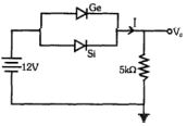
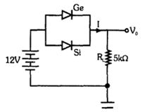
If $Si$ and $Ge$ diodes have barrier potentials of $0.7 \ V$ and $0.3 \ V$ respectively,as shown in the circuit,find the values of $V_0$ and $I$. If the $Ge$ diode connection is reversed,find the new values of $V_0$ and $I$ respectively.
A
$11.3 \ mA, 2.26 \ mA$
B
$2.34 \ mA, 2.20 \ mA$
C
$2.50 \ mA, 1.80 \ mA$
D
$10.2 \ mA, 3.20 \ mA$
Solution
(A) In the given circuit,the diodes are in parallel. The diode with the lower barrier potential will conduct first. Since $Ge$ $(0.3 \ V)$ has a lower barrier potential than $Si$ $(0.7 \ V)$,the $Ge$ diode will conduct.
$V_0 = 12 \ V - 0.3 \ V = 11.7 \ V$
$I = \frac{V_0}{R_L} = \frac{11.7 \ V}{5 \times 10^3 \ \Omega} = 2.34 \ mA$
If the $Ge$ diode is reversed,it becomes reverse-biased and does not conduct. The $Si$ diode will now conduct.
$V_0' = 12 \ V - 0.7 \ V = 11.3 \ V$
$I' = \frac{V_0'}{R_L} = \frac{11.3 \ V}{5 \times 10^3 \ \Omega} = 2.26 \ mA$
Thus,the values are $2.34 \ mA$ and $2.26 \ mA$ (for the reversed case).
0 likes
View Solution113
EasyMCQ
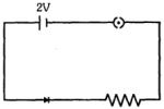
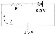
$A$ $2 \text{ V}$ battery is connected to a diode in forward bias. $A$ voltage of $0.5 \text{ V}$ is dropped across the diode,which is independent of the current flowing through it. $A$ current greater than $10 \text{ mA}$ causes excessive heating and damages the diode. If a current of $5 \text{ mA}$ is required in the diode,what value of series resistance must be connected in the circuit?
A
$3 \text{ k}\Omega$
B
$300 \text{ k}\Omega$
C
$300 \Omega$
D
$200 \text{ k}\Omega$
Solution
(C) Given:
Battery voltage $V = 2 \text{ V}$
Diode voltage drop $V_d = 0.5 \text{ V}$
Required current $I = 5 \text{ mA} = 5 \times 10^{-3} \text{ A}$
According to Kirchhoff's voltage law for the series circuit:
$V = V_d + I \times R$
$2 \text{ V} = 0.5 \text{ V} + (5 \times 10^{-3} \text{ A}) \times R$
$2 - 0.5 = 5 \times 10^{-3} \times R$
$1.5 = 5 \times 10^{-3} \times R$
$R = \frac{1.5}{5 \times 10^{-3}}$
$R = 0.3 \times 10^3 \Omega$
$R = 300 \Omega$
0 likes
View Solution114
DifficultMCQ
The forbidden energy gap of $Ge$ is $0.75 \ eV$. The maximum wavelength of incident photon radiation that can generate an electron-hole pair in a $Ge$ semiconductor is ........... $\mathring{A}$.
A
$4200$
B
$16500$
C
$4700$
D
$4000$
Solution
(B) The energy of the incident photon must be at least equal to the forbidden energy gap $(E_g)$ to create an electron-hole pair.
$E = E_g = 0.75 \ eV$
Using the relation between energy $(E)$ in $eV$ and wavelength $(\lambda)$ in $\mathring{A}$:
$E = \frac{12400}{\lambda (\mathring{A})}$
Rearranging for $\lambda$:
$\lambda = \frac{12400}{E_g} = \frac{12400}{0.75} \ \mathring{A}$
$\lambda = 16533.33 \ \mathring{A} \approx 16500 \ \mathring{A}$
Thus,the maximum wavelength is $16500 \ \mathring{A}$.
0 likes
View Solution115
EasyMCQ
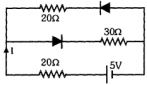
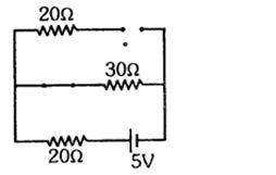
What will be the current flowing in the circuit?
A
$\frac{5}{40}$
B
$\frac{5}{50}$
C
$\frac{5}{10}$
D
$\frac{5}{20}$
Solution
(B) In the given circuit,the diode in the upper branch is in reverse bias. Therefore,no current flows through the $20 \, \Omega$ resistor in that branch.
Assuming the forward bias resistance of the diode in the middle branch is zero,the total resistance of the circuit is the sum of the $20 \, \Omega$ resistor in series with the battery and the $30 \, \Omega$ resistor in the middle branch.
Total resistance $R = 20 \, \Omega + 30 \, \Omega = 50 \, \Omega$.
The current $I$ flowing in the circuit is given by Ohm's law: $I = \frac{V}{R} = \frac{5 \, V}{50 \, \Omega} = \frac{5}{50} \, A$.
0 likes
View Solution116
MediumMCQ
In the given circuit,the voltage across the $P-N$ junction diode remains constant at $0.5 \ V$ regardless of the current. The maximum power rating of the diode is $100 \ mW$. What should be the value of $R$ in $\Omega$ to obtain the maximum current in the circuit?
A
$6.76$
B
$5$
C
$20$
D
$5.6$
Solution
(B) The maximum power rating of the diode is given by $P = V_D \times I_{max}$.
Given $P = 100 \ mW = 100 \times 10^{-3} \ W$ and $V_D = 0.5 \ V$.
Substituting the values: $100 \times 10^{-3} = 0.5 \times I_{max}$.
$I_{max} = \frac{100 \times 10^{-3}}{0.5} = 200 \times 10^{-3} \ A = 200 \ mA$.
Applying Kirchhoff's voltage law to the circuit: $V_{source} = I_{max} \times R + V_D$.
$1.5 = (200 \times 10^{-3}) \times R + 0.5$.
$1.5 - 0.5 = 0.2 \times R$.
$1.0 = 0.2 \times R$.
$R = \frac{1.0}{0.2} = 5 \ \Omega$.
0 likes
View Solution117
DifficultMCQ
$A$ $P-N$ junction has a potential barrier of $0.5 \ V$. If an electron enters the $P-N$ junction diode from the $N$-side with a speed of $5 \times 10^5 \ m/s$,what will be its speed when it emerges from the $P$-side?
A
$5.1 \times 10^4 \ m/s$
B
$2.1 \times 10^4 \ m/s$
C
$2.7 \times 10^2 \ m/s$
D
$2.7 \times 10^5 \ m/s$
Solution
(D) The potential barrier $V = 0.5 \ V$. The mass of an electron $m = 9.1 \times 10^{-31} \ kg$ and its charge $e = 1.6 \times 10^{-19} \ C$.
According to the law of conservation of energy,the initial kinetic energy of the electron is equal to the final kinetic energy plus the potential energy barrier it must overcome:
$\frac{1}{2}mv_i^2 = \frac{1}{2}mv_f^2 + eV$
$\frac{1}{2}mv_f^2 = \frac{1}{2}mv_i^2 - eV$
$v_f^2 = v_i^2 - \frac{2eV}{m}$
$v_f = \sqrt{v_i^2 - \frac{2eV}{m}}$
Substituting the values:
$v_f = \sqrt{(5 \times 10^5)^2 - \frac{2 \times 1.6 \times 10^{-19} \times 0.5}{9.1 \times 10^{-31}}}$
$v_f = \sqrt{25 \times 10^{10} - \frac{1.6 \times 10^{-19}}{9.1 \times 10^{-31}}}$
$v_f = \sqrt{25 \times 10^{10} - 0.1758 \times 10^{12}}$
$v_f = \sqrt{25 \times 10^{10} - 17.58 \times 10^{10}}$
$v_f = \sqrt{7.42 \times 10^{10}} \approx 2.72 \times 10^5 \ m/s$.
0 likes
View Solution118
MediumMCQ
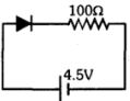
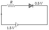
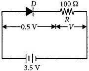
As shown in the figure,a diode is connected to an external resistor. Assume that the barrier potential developed in the diode is $0.5 \ V$. Find the value of the current in the circuit in milliamperes. (in $mA$)
A
$50$
B
$30$
C
$40$
D
$25$
Solution
(C) Given: Battery voltage $E = 4.5 \ V$,Barrier potential $V_b = 0.5 \ V$,Resistance $R = 100 \ \Omega$.
The effective voltage $V$ across the resistor is the battery voltage minus the barrier potential of the diode:
$V = E - V_b = 4.5 \ V - 0.5 \ V = 4.0 \ V$.
Using Ohm's law,the current $I$ in the circuit is:
$I = \frac{V}{R} = \frac{4.0 \ V}{100 \ \Omega} = 0.04 \ A$.
To convert the current to milliamperes $(mA)$:
$I = 0.04 \ \text{A} \times 1000 \ \text{mA/A} = 40 \ mA$.
0 likes
View Solution119
MediumMCQ
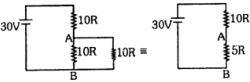
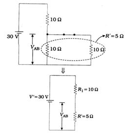
For the circuit shown in the figure,$V_{AB} = $ ....... $V$.
A
$10$
B
$20$
C
$30$
D
$5$
Solution
(A) The diode $D$ is in forward bias,so we can replace it with a short circuit (assuming an ideal diode with zero resistance).
Now,the $10 \ \Omega$ resistor in the middle and the $10 \ \Omega$ resistor on the right are in parallel.
The equivalent resistance $R'$ of these two parallel resistors is:
$R' = \frac{10 \times 10}{10 + 10} = 5 \ \Omega$.
Now,the circuit simplifies to a series circuit with a $30 \ V$ source,a $10 \ \Omega$ resistor $(R_1)$,and the equivalent $5 \ \Omega$ resistor $(R')$.
Using the voltage divider rule,the voltage $V_{AB}$ across the parallel combination is:
$V_{AB} = V \times \frac{R'}{R_1 + R'} = 30 \times \frac{5}{10 + 5} = 30 \times \frac{5}{15} = 10 \ V$.
0 likes
View Solution120
MediumMCQ
$A$ $P-N$ junction diode is in forward bias with a current of $10 \ mA$. The potential drop across the diode is $0.5 \ V$. Assuming the current is independent of the potential,what is the maximum voltage of the battery in series with a $200 \ \Omega$ resistor to maintain this forward bias condition? (in $V$)
A
$1.8$
B
$4.2$
C
$2.5$
D
$3$
Solution
(C) Given: Current $I = 10 \ mA = 10 \times 10^{-3} \ A$,Potential drop across diode $V_d = 0.5 \ V$,Series resistance $R = 200 \ \Omega$.
The total voltage $V$ supplied by the battery is the sum of the voltage drop across the resistor and the voltage drop across the diode.
$V = V_R + V_d$
Using Ohm's law for the resistor,$V_R = I \times R$.
$V_R = (10 \times 10^{-3} \ A) \times (200 \ \Omega) = 2 \ V$.
Therefore,the total voltage $V = 2 \ V + 0.5 \ V = 2.5 \ V$.
0 likes
View Solution121
EasyMCQ
$A$ thermistor is usually made of......
A
Metals with a low temperature coefficient of resistivity
B
Metals with a high temperature coefficient of resistivity
C
Metal oxides with a high temperature coefficient of resistivity
D
Semiconducting materials with a low temperature coefficient of resistivity
Solution
(C) thermistor is a type of resistor whose resistance is significantly dependent on temperature.
Thermistors are typically composed of sintered mixtures of metallic oxides,such as manganese,nickel,cobalt,and copper.
These materials exhibit a high temperature coefficient of resistivity,meaning their resistance changes drastically with small changes in temperature.
Therefore,the correct option is $C$.
0 likes
View Solution122
MediumMCQ
The potential barrier of a $P-N$ junction is $0.5 \ V$. The thickness of the depletion layer is $5.0 \times 10^{-7} \ m$. Calculate the electric field.
A
$1.0 \times 10^6 \ V/m$
B
$1.0 \times 10^5 \ V/m$
C
$2.0 \times 10^5 \ V/m$
D
$2.0 \times 10^6 \ V/m$
Solution
(A) The electric field $E$ in a depletion layer is given by the relation $E = \frac{V}{d}$,where $V$ is the potential barrier and $d$ is the thickness of the depletion layer.
Given: $V = 0.5 \ V$ and $d = 5.0 \times 10^{-7} \ m$.
Substituting the values:
$E = \frac{0.5}{5.0 \times 10^{-7}}$
$E = \frac{0.5}{5.0} \times 10^7$
$E = 0.1 \times 10^7 \ V/m$
$E = 1.0 \times 10^6 \ V/m$.
Therefore,the electric field is $1.0 \times 10^6 \ V/m$.
Given: $V = 0.5 \ V$ and $d = 5.0 \times 10^{-7} \ m$.
Substituting the values:
$E = \frac{0.5}{5.0 \times 10^{-7}}$
$E = \frac{0.5}{5.0} \times 10^7$
$E = 0.1 \times 10^7 \ V/m$
$E = 1.0 \times 10^6 \ V/m$.
Therefore,the electric field is $1.0 \times 10^6 \ V/m$.
0 likes
View Solution123
MediumMCQ
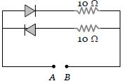
The forward resistance of the diode is zero and the reverse resistance is infinite. When the positive terminal of a $2 \ V$ battery is connected to point $A$ and the negative terminal to point $B$,what current will flow through the circuit (in $A$)?
A
$0.2$
B
$0.4$
C
$0$
D
$0.1$
Solution
(A) In the given circuit,there are two parallel branches,each containing a diode in series with a $10 \ \Omega$ resistor.
When the positive terminal of the battery is connected to $A$ and the negative terminal to $B$,the top diode is forward-biased,while the bottom diode is reverse-biased.
For the top branch: The diode acts as a short circuit (zero resistance). The total resistance is $R_1 = 10 \ \Omega$. The current is $I_1 = \frac{V}{R_1} = \frac{2 \ V}{10 \ \Omega} = 0.2 \ A$.
For the bottom branch: The diode acts as an open circuit (infinite resistance). The current is $I_2 = 0 \ A$.
The total current in the circuit is $I = I_1 + I_2 = 0.2 \ A + 0 \ A = 0.2 \ A$.
0 likes
View Solution124
MediumMCQ
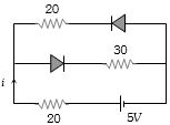
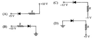
Find the current $i$ in the circuit.
A
$\frac{5}{40} \text{ A}$
B
$\frac{5}{50} \text{ A}$
C
$\frac{5}{10} \text{ A}$
D
$\frac{5}{20} \text{ A}$
Solution
(B) In the given circuit,the top diode is reverse-biased because the positive terminal of the battery is connected to its cathode. Therefore,no current flows through the top branch.
The bottom diode is forward-biased because the positive terminal of the battery is connected to its anode. Thus,current flows through the bottom branch.
The total resistance in the active branch is $R = 20 \, \Omega + 30 \, \Omega = 50 \, \Omega$.
The voltage source is $V = 5 \text{ V}$.
Using Ohm's law,the current $i$ is given by $i = \frac{V}{R} = \frac{5}{50} \text{ A}$.
0 likes
View Solution125
EasyMCQ
Find the current $I$ in the circuit in $amp$.
A
$0$
B
$1$
C
$0.1$
D
$0.2$
Solution
(A) The circuit consists of a diode,a resistor of $3 \ \Omega$,and two voltage sources of $-4 \ V$ and $-1 \ V$.
To determine if the diode is forward-biased or reverse-biased,we look at the potentials at its terminals.
The potential at the anode (p-side) is $-4 \ V$.
The potential at the cathode (n-side) is $-1 \ V$.
Since the potential at the cathode $(-1 \ V)$ is higher than the potential at the anode $(-4 \ V)$,the diode is reverse-biased.
In a reverse-biased state,an ideal diode acts as an open circuit,meaning it offers infinite resistance.
Therefore,no current flows through the circuit.
Thus,the current $I = 0 \ A$.
0 likes
View Solution126
DifficultMCQ
The diode voltage is $0.5 \ V$ and the maximum power rating is $100 \ mW$. To obtain the maximum current in the circuit,the value of $R$ should be .......... $\Omega$.
A
$1.5$
B
$5$
C
$6.67$
D
$200$
Solution
(B) The maximum current $I$ that the diode can handle is given by $I = \frac{P}{V} = \frac{100 \times 10^{-3} \ W}{0.5 \ V} = 0.2 \ A$.
Applying Kirchhoff's Voltage Law to the circuit,the voltage across the resistor $R$ is $V_R = 1.5 \ V - 0.5 \ V = 1.0 \ V$.
Using Ohm's law,the resistance $R$ is $R = \frac{V_R}{I} = \frac{1.0 \ V}{0.2 \ A} = 5 \ \Omega$.
Applying Kirchhoff's Voltage Law to the circuit,the voltage across the resistor $R$ is $V_R = 1.5 \ V - 0.5 \ V = 1.0 \ V$.
Using Ohm's law,the resistance $R$ is $R = \frac{V_R}{I} = \frac{1.0 \ V}{0.2 \ A} = 5 \ \Omega$.
0 likes
View Solution127
EasyMCQ
Which diode is in forward bias?
A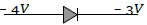
B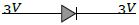
C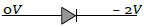
D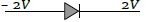
Solution
(C) $PN$ junction diode is in forward bias when the potential at the $P$-terminal (anode) is higher than the potential at the $N$-terminal (cathode).
In the given options:
$(A)$ $P$-terminal = $-4 \ V$,$N$-terminal = $-3 \ V$. Since $-4 \ V < -3 \ V$,it is reverse biased.
$(B)$ $P$-terminal = $3 \ V$,$N$-terminal = $3 \ V$. Potential difference is $0 \ V$,so it is not forward biased.
$(C)$ $P$-terminal = $0 \ V$,$N$-terminal = $-2 \ V$. Since $0 \ V > -2 \ V$,it is forward biased.
$(D)$ $P$-terminal = $-2 \ V$,$N$-terminal = $2 \ V$. Since $-2 \ V < 2 \ V$,it is reverse biased.
Therefore,the correct option is $(C)$.
0 likes
View Solution128
MediumMCQ
In the following figure,the diodes which are forward biased,are
A
$A, B, D$
B
$C$
C
$A, C$
D
$B, D$
Solution
(C) $p-n$ junction diode is forward biased when the potential at the $p$-side is higher than the potential at the $n$-side.
$(A)$ $p$-side is at $+5 \ V$ and $n$-side is at $+10 \ V$. Since $5 \ V < 10 \ V$,it is reverse biased.
$(B)$ $p$-side is at $-10 \ V$ and $n$-side is at $0 \ V$ (ground). Since $-10 \ V < 0 \ V$,it is reverse biased.
$(C)$ $p$-side is at $-12 \ V$ and $n$-side is at $-5 \ V$. Since $-12 \ V < -5 \ V$,it is reverse biased.
$(D)$ $p$-side is at $0 \ V$ (ground) and $n$-side is at $+5 \ V$. Since $0 \ V < 5 \ V$,it is reverse biased.
Wait,let's re-examine the diode symbols in the image:
$(A)$ Diode points towards $+5 \ V$. $p$-side is at $+10 \ V$ (via resistor),$n$-side is at $+5 \ V$. $10 > 5$,so forward biased.
$(B)$ Diode points towards ground. $p$-side is at $-10 \ V$,$n$-side is at $0 \ V$. $-10 < 0$,so reverse biased.
$(C)$ Diode points towards $-12 \ V$. $p$-side is at $-5 \ V$,$n$-side is at $-12 \ V$. $-5 > -12$,so forward biased.
$(D)$ Diode points towards ground. $p$-side is at $0 \ V$,$n$-side is at $+5 \ V$. $0 < 5$,so reverse biased.
Thus,diodes $(A)$ and $(C)$ are forward biased.
0 likes
View Solution129
EasyMCQ
In forward biasing of the $p-n$ junction:
A
the positive terminal of the battery is connected to $p-$side and the depletion region becomes thick.
B
the positive terminal of the battery is connected to $n-$side and the depletion region becomes thick.
C
the positive terminal of the battery is connected to $n-$side and the depletion region becomes thin.
D
the positive terminal of the battery is connected to $p-$side and the depletion region becomes thin.
Solution
(D) In forward biasing,the positive terminal of the battery is connected to the $p-$side and the negative terminal is connected to the $n-$side of the $p-n$ junction.
This external voltage opposes the internal potential barrier of the junction.
As a result,the majority charge carriers are pushed towards the junction,which reduces the width of the depletion region.
Therefore,the depletion region becomes thin.
This external voltage opposes the internal potential barrier of the junction.
As a result,the majority charge carriers are pushed towards the junction,which reduces the width of the depletion region.
Therefore,the depletion region becomes thin.
0 likes
View Solution130
MediumMCQ
Two ideal diodes are connected to a battery as shown in the circuit. The current supplied by the battery is......$A$
A
$0$
B
$0.75$
C
$0.25$
D
$0.5$
Solution
(D) In the given circuit,the upper diode $D_1$ is forward-biased because its p-side is connected to the positive terminal of the battery.
The lower diode $D_2$ is reverse-biased because its n-side is connected to the positive terminal of the battery.
An ideal diode in forward bias acts as a short circuit (zero resistance),and an ideal diode in reverse bias acts as an open circuit (infinite resistance).
Therefore,no current flows through the branch containing $D_2$.
The total current supplied by the battery flows only through the branch containing $D_1$ and the $10 \ \Omega$ resistor.
Using Ohm's law,$I = \frac{V}{R} = \frac{5 \ V}{10 \ \Omega} = 0.5 \ A$.
0 likes
View Solution131
EasyMCQ
The barrier potential of a $p-n$ junction depends on:
$(1)$ Type of semiconductor material
$(2)$ Amount of doping
$(3)$ Temperature
Which one of the following is correct?
$(1)$ Type of semiconductor material
$(2)$ Amount of doping
$(3)$ Temperature
Which one of the following is correct?
A
$1$ and $2$ only
B
$2$ only
C
$2$ and $3$ only
D
$1, 2$ and $3$
Solution
(D) The barrier potential $(V_b)$ of a $p-n$ junction is determined by the following factors:
$1$. Type of semiconductor material: The band gap energy differs for different materials. For $Si$,$V_b \approx 0.7 \ V$,and for $Ge$,$V_b \approx 0.3 \ V$.
$2$. Amount of doping: The concentration of impurity atoms affects the width of the depletion region and the potential difference across it.
$3$. Temperature: The barrier potential decreases with an increase in temperature because the intrinsic carrier concentration increases,which affects the Fermi level and the built-in potential.
Therefore,all three factors $(1, 2, 3)$ influence the barrier potential.
0 likes
View Solution132
MediumMCQ
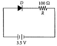
In the given figure,a diode $D$ is connected to an external resistance $R = 100 \,\Omega$ and an $e.m.f.$ of $3.5 \,V$. If the barrier potential developed across the diode is $0.5 \,V$,the current in the circuit will be ........ $mA$.
A
$35$
B
$30$
C
$40$
D
$20$
Solution
(B) The potential difference across the resistance $R$ is given by subtracting the barrier potential of the diode from the total $e.m.f.$ of the circuit:
$V_R = E - V_{\text{barrier}} = 3.5 \,V - 0.5 \,V = 3.0 \,V$
According to Ohm's law,the current $I$ in the circuit is:
$I = \frac{V_R}{R} = \frac{3.0 \,V}{100 \,\Omega} = 0.03 \,A$
To convert the current into milliamperes $(mA)$:
$I = 0.03 \,A \times 1000 \,mA/A = 30 \,mA$
Therefore,the current in the circuit is $30 \,mA$.
0 likes
View Solution133
MediumMCQ
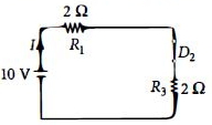
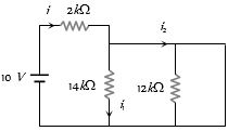
The given circuit has two ideal diodes connected as shown in the figure. The current flowing through the resistance $R_1$ will be.....$ A$
A
$1.43$
B
$3.13$
C
$2.5$
D
$10$
Solution
(C) In the given circuit,diode $D_1$ is reverse biased because its p-terminal is at a lower potential than its n-terminal,so it acts as an open circuit and blocks the current.
Diode $D_2$ is forward biased because its p-terminal is at a higher potential than its n-terminal,so it acts as a closed switch (ideal diode).
Hence,the equivalent circuit consists of the $10 \ V$ battery,resistance $R_1 = 2 \ \Omega$,and resistance $R_3 = 2 \ \Omega$ in series.
The total resistance of the circuit is $R_{eq} = R_1 + R_3 = 2 \ \Omega + 2 \ \Omega = 4 \ \Omega$.
The current flowing through the resistance $R_1$ is given by $I = \frac{V}{R_{eq}} = \frac{10 \ V}{4 \ \Omega} = 2.5 \ A$.
0 likes
View Solution134
EasyMCQ
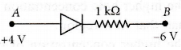
Consider the junction diode as ideal. The value of current flowing through $AB$ is
A
$10^{-2}\;A$
B
$10^{-1}\;A$
C
$10^{-3}\;A$
D
$0\;A$
Solution
(A) The $p-n$ junction diode is forward biased because the $p$-terminal is at a higher potential $(+4\;V)$ than the $n$-terminal $(-6\;V)$.
An ideal diode in forward bias acts as a short circuit (zero resistance).
Therefore,the current $I_{AB}$ flowing through the circuit is given by Ohm's law:
$I_{AB} = \frac{V_A - V_B}{R} = \frac{4\;V - (-6\;V)}{1\;k\Omega} = \frac{10\;V}{1000\;\Omega} = 10^{-2}\;A$.
An ideal diode in forward bias acts as a short circuit (zero resistance).
Therefore,the current $I_{AB}$ flowing through the circuit is given by Ohm's law:
$I_{AB} = \frac{V_A - V_B}{R} = \frac{4\;V - (-6\;V)}{1\;k\Omega} = \frac{10\;V}{1000\;\Omega} = 10^{-2}\;A$.
0 likes
View Solution135
MediumMCQ
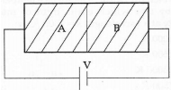
Two sides of a semiconductor germanium crystal $A$ and $B$ are doped with arsenic and indium respectively. They are connected to a battery as shown in the figure. The correct graph between current and voltage for the arrangement is:
A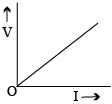
B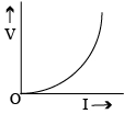
C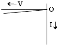
D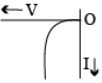
Solution
(B) $1$. Semiconductor $A$ is doped with arsenic (a pentavalent impurity),making it an $n$-type semiconductor.
$2$. Semiconductor $B$ is doped with indium (a trivalent impurity),making it a $p$-type semiconductor.
$3$. The junction formed by $A$ ($n$-type) and $B$ ($p$-type) is a $p-n$ junction diode.
$4$. In the figure,the positive terminal of the battery is connected to $B$ ($p$-side) and the negative terminal is connected to $A$ ($n$-side). This configuration is forward biasing.
$5$. For a forward-biased $p-n$ junction,the current increases exponentially with the applied voltage,as shown in the standard $V-I$ characteristic curve for a diode in the first quadrant.
0 likes
View Solution136
EasyMCQ
Which one of the following represents a forward-biased diode?
A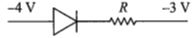
B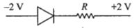
C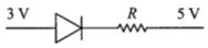
D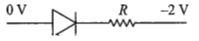
Solution
(D) $p-n$ junction diode is said to be forward-biased if the potential at the $p$-side $(V_p)$ is higher than the potential at the $n$-side $(V_n)$,i.e.,$V_p > V_n$.
Let us analyze each option:
$A$: $V_p = -4 \text{ V}$,$V_n = -3 \text{ V}$. Here,$-4 < -3$,so $V_p < V_n$ (Reverse biased).
$B$: $V_p = -2 \text{ V}$,$V_n = +2 \text{ V}$. Here,$-2 < +2$,so $V_p < V_n$ (Reverse biased).
$C$: $V_p = 3 \text{ V}$,$V_n = 5 \text{ V}$. Here,$3 < 5$,so $V_p < V_n$ (Reverse biased).
$D$: $V_p = 0 \text{ V}$,$V_n = -2 \text{ V}$. Here,$0 > -2$,so $V_p > V_n$ (Forward biased).
Therefore,option $D$ represents a forward-biased diode.
0 likes
View Solution137
EasyMCQ
In a $p-n$ junction diode,change in temperature due to heating
A
affects only reverse resistance
B
affects only forward resistance
C
affects the overall $V-I$ characteristics of $p-n$ junction
D
does not affect resistance of $p-n$ junction
Solution
(C) When the temperature of a $p-n$ junction diode increases,the thermal energy causes more covalent bonds to break,resulting in an increase in the number of electron-hole pairs.
This increase in charge carriers leads to a decrease in the resistance of the semiconductor material.
Consequently,both the forward current and the reverse saturation current are significantly affected.
Therefore,the overall $V-I$ characteristics of the $p-n$ junction diode are altered by the change in temperature.
0 likes
View Solution138
DifficultMCQ
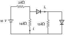
In the following circuit,the currents $i_1$ and $i_2$ are respectively:
A
$0, 0$
B
$5\, mA, 5\, mA$
C
$5\, mA, 0$
D
$0, 5\, mA$
Solution
(D) In the given circuit,the first diode is reverse-biased because the potential at its anode is lower than the potential at its cathode (due to the $14\, k\Omega$ resistor path to ground). Therefore,no current flows through the first diode branch.
Consequently,the circuit simplifies to a series combination of the $10\, V$ source and the $2\, k\Omega$ resistor. The current $i$ flowing through this branch is:
$i = \frac{10\, V}{2\, k\Omega} = 5\, mA$.
Since the first diode is open-circuited,$i_1 = 0$.
The current $i_2$ flows through the second diode,which is forward-biased. Thus,$i_2 = i = 5\, mA$.
Therefore,$i_1 = 0$ and $i_2 = 5\, mA$.
0 likes
View Solution139
EasyMCQ
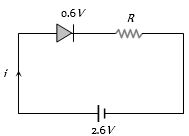
When a silicon $PN$ junction is in forward biased condition with a series resistance,it has a knee voltage of $0.6\, V$. The current flowing through it is $5\, mA$ when the $PN$ junction is connected to a $2.6\, V$ battery. The value of the series resistance is.....$\Omega$.
A
$100$
B
$200$
C
$400$
D
$500$
Solution
(C) In a forward-biased $PN$ junction circuit with a series resistance $R$,the total voltage $V$ of the battery is equal to the sum of the knee voltage $V_k$ of the diode and the voltage drop across the resistor $V_R$.
According to Kirchhoff's voltage law:
$V = V_k + I \times R$
Given:
Battery voltage $V = 2.6\, V$
Knee voltage $V_k = 0.6\, V$
Current $I = 5\, mA = 5 \times 10^{-3}\, A$
Substituting the values into the equation:
$2.6 = 0.6 + (5 \times 10^{-3}) \times R$
$2.0 = 5 \times 10^{-3} \times R$
$R = \frac{2.0}{5 \times 10^{-3}}$
$R = 0.4 \times 10^3 = 400\,\Omega$.
Therefore,the value of the series resistance is $400\,\Omega$.
0 likes
View Solution140
MediumMCQ
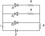
In the following circuit of $PN$ junction diodes $D_1, D_2$ and $D_3$ are ideal,then the current $i$ is:
A
$E/R$
B
$E/2R$
C
$2E/3R$
D
Zero
Solution
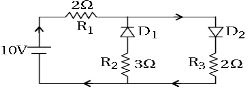
(A) In the given circuit,the diodes $D_1, D_2,$ and $D_3$ are connected in parallel with the battery $E$.
By observing the polarity of the diodes:
$D_1$ is forward biased because its $p$-terminal is connected to the positive terminal of the battery.
$D_2$ is reverse biased because its $p$-terminal is connected to the negative terminal of the battery (relative to the $n$-terminal).
$D_3$ is forward biased because its $p$-terminal is connected to the positive terminal of the battery.
Since the diodes are ideal,the forward-biased diodes act as short circuits (zero resistance) and the reverse-biased diode acts as an open circuit (infinite resistance).
The circuit simplifies to a single loop containing the battery $E$ and the resistor $R$ in series.
Therefore,the current $i$ is given by $i = E/R$.
0 likes
View Solution141
MediumMCQ
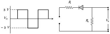
$A$ waveform is applied to the following circuit. Assuming an ideal diode and ${R_1} = {R_2}$, which of the following output waveforms will be produced?
A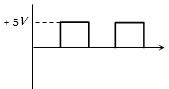
B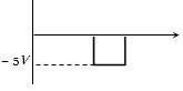
C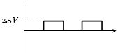
D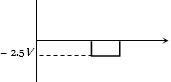
Solution
(D) The circuit consists of a series resistor ${R_1}$ and a parallel resistor ${R_2}$ with a diode in series with ${R_1}$.
For the positive half-cycle of the input voltage $(+5V)$, the diode is reverse-biased and acts as an open circuit. Therefore, no current flows through ${R_2}$, and the output voltage ${V_0} = 0V$.
For the negative half-cycle of the input voltage $(-5V)$, the diode is forward-biased and acts as a short circuit. The circuit becomes a voltage divider with ${R_1}$ and ${R_2}$ in series across the $-5V$ source.
Since ${R_1} = {R_2}$, the voltage across ${R_2}$ is given by the voltage divider rule: ${V_0} = V_{in} \times \frac{R_2}{R_1 + R_2} = -5V \times \frac{R_2}{R_2 + R_2} = -5V \times \frac{1}{2} = -2.5V$.
Thus, the output waveform will show $0V$ during the positive cycle and $-2.5V$ during the negative cycle.
0 likes
View Solution142
DifficultMCQ
The current-voltage relation of a diode is given by $I = (e^{1000V/T} - 1) \; mA$,where the applied voltage $V$ is in volts and the temperature $T$ is in Kelvin. If a student makes an error of $\pm 0.01 \; V$ while measuring the voltage to obtain a current of $5 \; mA$ at $300 \; K$,what will be the error in the value of the current in $mA$?
A
$0.02$
B
$0.5$
C
$0.05$
D
$0.2$
Solution
(D) Given the relation: $I = (e^{1000V/T} - 1) \; mA$.
At $I = 5 \; mA$,we have $5 = e^{1000V/T} - 1$,which implies $e^{1000V/T} = 6$.
Differentiating the expression for $I$ with respect to $V$:
$\frac{dI}{dV} = e^{1000V/T} \times \frac{1000}{T}$.
For small errors,we can write $\Delta I = \frac{dI}{dV} \Delta V$.
Substituting the known values: $\Delta I = (e^{1000V/T}) \times \frac{1000}{T} \times \Delta V$.
Since $e^{1000V/T} = 6$,$T = 300 \; K$,and $\Delta V = 0.01 \; V$:
$\Delta I = 6 \times \frac{1000}{300} \times 0.01$.
$\Delta I = 6 \times \frac{10}{3} \times 0.01 = 20 \times 0.01 = 0.2 \; mA$.
0 likes
View Solution143
EasyMCQ
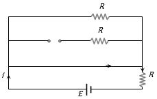
In the following circuits,which one of the diodes is reverse biased?
A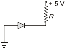
B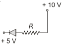
C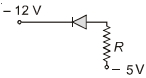
D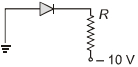
Solution
(A) diode is reverse biased when its $p$-side is connected to a lower potential and its $n$-side is connected to a higher potential.
Let us analyze the options:
$A$: The $p$-side is at $0 \ V$ (ground) and the $n$-side is at $+5 \ V$. Since $0 \ V < +5 \ V$,this is reverse biased.
$B$: The $p$-side is at $+5 \ V$ and the $n$-side is at $+10 \ V$. Since $5 \ V < 10 \ V$,this is also reverse biased.
$C$: The $p$-side is at $-12 \ V$ and the $n$-side is at $-5 \ V$. Since $-12 \ V < -5 \ V$,this is also reverse biased.
$D$: The $p$-side is at $0 \ V$ (ground) and the $n$-side is at $-10 \ V$. Since $0 \ V > -10 \ V$,this is forward biased.
Note: In standard multiple-choice questions of this type,usually only one option is intended to be correct. However,based on the provided diagrams,options $A$,$B$,and $C$ all represent reverse-biased configurations. Given the typical structure,$A$ is the most standard representation of a reverse-biased diode.
0 likes
View Solution144
MediumMCQ
The circuit has two oppositely connected ideal diodes in parallel. What is the current flowing in the circuit (in $A$)?
A
$1.33$
B
$1.71$
C
$2$
D
$2.31$
Solution
(C) In the given circuit,the positive terminal of the $12 \ V$ battery is connected such that diode $D_2$ is forward-biased and diode $D_1$ is reverse-biased.
Since $D_1$ is reverse-biased,it acts as an open circuit and no current flows through the $3 \ \Omega$ resistor branch.
Since $D_2$ is forward-biased and ideal,it acts as a short circuit. The current flows through the $4 \ \Omega$ resistor and the $2 \ \Omega$ resistor branch.
The total resistance of the circuit is $R = 4 \ \Omega + 2 \ \Omega = 6 \ \Omega$.
Using Ohm's law,the current $i$ in the circuit is given by:
$i = \frac{V}{R} = \frac{12 \ V}{6 \ \Omega} = 2 \ A$.
0 likes
View Solution145
EasyMCQ
The forward biased diode connection is:
A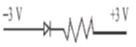
B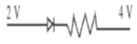
C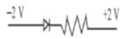
D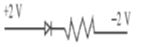
Solution
(D) For a $p-n$ junction diode to be in forward bias,the $p$-side must be connected to a higher potential than the $n$-side.
Let $V_p$ be the potential at the $p$-side and $V_n$ be the potential at the $n$-side.
Forward bias condition: $V_p > V_n$.
Evaluating the options:
$(A)$ $V_p = -3 \ V, V_n = +3 \ V \implies V_p < V_n$ (Reverse bias)
$(B)$ $V_p = 2 \ V, V_n = 4 \ V \implies V_p < V_n$ (Reverse bias)
$(C)$ $V_p = -2 \ V, V_n = +2 \ V \implies V_p < V_n$ (Reverse bias)
$(D)$ $V_p = +2 \ V, V_n = -2 \ V \implies V_p > V_n$ (Forward bias)
Therefore,option $(D)$ is the correct connection for a forward biased diode.

0 likes
View Solution146
MediumMCQ
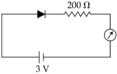
The reading of the ammeter for a silicon diode in the given circuit is ....... $mA$.
A
$15$
B
$13.5$
C
$11.5$
D
$0$
Solution
(C) From the given circuit diagram,the silicon diode is connected in forward bias.
The potential barrier (knee voltage) for a silicon diode is $\Delta V = 0.7 \ V$.
The net voltage across the resistor $R = 200 \ \Omega$ is $V_{net} = V - \Delta V = 3 \ V - 0.7 \ V = 2.3 \ V$.
Using Ohm's law,the current $I$ in the circuit is:
$I = \frac{V_{net}}{R} = \frac{2.3 \ V}{200 \ \Omega} = 0.0115 \ A$.
Converting the current to milliamperes $(mA)$:
$I = 0.0115 \times 1000 \ mA = 11.5 \ mA$.
0 likes
View Solution147
MediumMCQ
Diffusion current in a $p-n$ junction is greater than the drift current in magnitude when:
A
The junction is forward-biased.
B
The junction is reverse-biased.
C
The junction is unbiased.
D
In no case.
Solution
(A) In a $p-n$ junction,the diffusion current $(I_{diff})$ is caused by the concentration gradient of charge carriers,while the drift current $(I_{drift})$ is caused by the electric field in the depletion region.
When the junction is forward-biased,the external voltage reduces the potential barrier,which allows a large number of majority carriers to diffuse across the junction,significantly increasing the diffusion current.
Conversely,the drift current remains relatively small and constant as it depends on the minority carriers,which are thermally generated.
Therefore,in a forward-biased $p-n$ junction,the magnitude of the diffusion current is much greater than that of the drift current.
0 likes
View Solution148
MediumMCQ
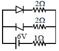
Assuming an ideal diode,find the current through the $1 \Omega$ resistance in the circuit shown in the figure.
A
$2 \ A$
B
$1 \ A$
C
$3 \ A$
D
None of the above
Solution
(A) In the given circuit,the top branch contains a diode in forward bias,and the middle branch contains a Zener diode in reverse bias (as the cathode is connected to the positive terminal of the battery).
$1$. The diode in the top branch is in forward bias,so it acts as a short circuit (ideal diode). The resistance in this branch is $2 \Omega$.
$2$. The Zener diode in the middle branch is in reverse bias,so it acts as an open circuit. No current flows through this branch.
$3$. The total resistance of the circuit is the resistance of the top branch $(2 \Omega)$ in parallel with the middle branch (open circuit,so infinite resistance),which is $2 \Omega$. This is then in series with the $1 \Omega$ internal resistance.
$4$. Total resistance $R_{eq} = 2 \Omega + 1 \Omega = 3 \Omega$.
$5$. The current through the $1 \Omega$ resistor is the total current supplied by the $6 \ V$ battery: $I = \frac{V}{R_{eq}} = \frac{6 \ V}{3 \Omega} = 2 \ A$.
0 likes
View SolutionSemiconductor Electronics — PN Junction and Diode · Frequently Asked Questions
1Are these Semiconductor Electronics questions useful for JEE and NEET?
Yes. All questions in this section are mapped to JEE Main and NEET exam patterns. Previous year questions from JEE Main, NEET, GUJCET and state-level exams are included with full solutions.
2Can I switch to Hindi or Gujarati for these questions?
Yes. Use the language tabs in the hero section or the sidebar to view the same questions and solutions in English, Hindi or Gujarati.
3How do I generate a question paper from this subtopic?
Use the Vedclass Exam Paper Generator — select the chapter and subtopic, set difficulty, and generate Sets A, B, C, D automatically. First 3 chapters of every subject are free.
Vedclass Products
For Students
Vedclass Test Series
Mock tests in real JEE/NEET style with performance analysis. 5-day free trial.
Start Free TrialFor Teachers
Exam Paper Generator
Generate Set A/B/C/D papers from this chapter in 2 minutes. 3 chapters free.
Try FreeFor Institutes
Online Exam Module
Live online exams with unlimited students, 360° analytics & white-label branding.
See DemoFor Teachers & Institutes
Generate a Semiconductor Electronics Exam Paper in 2 Minutes
Select subtopic & difficulty — Sets A, B, C, D auto-generated with No Repeat logic.
First 3 chapters of every subject are free — no payment required.