
A English
Faraday's and Lenz's Law Questions in English
Class 12 Physics · Electromagnetic Induction · Faraday's and Lenz's Law
310+
Questions
English
Language
100%
With Solutions
Showing 49 of 310 questions in English
151
MediumMCQ
If we move a magnet towards a coil,keeping the $N$ pole in front of the coil,then that side of the coil behaves as which pole?
A
$N$ pole
B
$S$ pole
C
Does not behave as a pole
D
Depends on the speed of the magnet
Solution
(A) According to Lenz's Law,the direction of the induced current in a coil is such that it opposes the change in magnetic flux that produced it.
When the $N$ pole of a magnet is moved towards a coil,the magnetic flux through the coil increases.
To oppose this increase,the coil develops a magnetic polarity that repels the approaching $N$ pole.
Since like poles repel,the side of the coil facing the magnet must behave as an $N$ pole.
When the $N$ pole of a magnet is moved towards a coil,the magnetic flux through the coil increases.
To oppose this increase,the coil develops a magnetic polarity that repels the approaching $N$ pole.
Since like poles repel,the side of the coil facing the magnet must behave as an $N$ pole.
0 likes
View Solution152
Difficult
Derive the relation between induced charge and change in magnetic flux.
Solution
(N/A) From Faraday's law,the magnitude of the induced electromotive force (emf) is given by:
$|\varepsilon| = \frac{\Delta \Phi_{B}}{\Delta t} \quad \dots(1)$
We also know that the induced current $I$ is related to the induced emf by Ohm's law,$|\varepsilon| = I r$,where $r$ is the resistance of the coil. Since $I = \frac{\Delta Q}{\Delta t}$,we can write:
$|\varepsilon| = \frac{\Delta Q}{\Delta t} r \quad \dots(2)$
Equating $(1)$ and $(2)$:
$\frac{\Delta \Phi_{B}}{\Delta t} = \frac{\Delta Q}{\Delta t} r$
Canceling $\Delta t$ from both sides,we get:
$\Delta \Phi_{B} = \Delta Q \cdot r$
Therefore,the induced charge is:
$\Delta Q = \frac{\Delta \Phi_{B}}{r}$
This shows that the induced charge depends only on the total change in magnetic flux and the resistance of the circuit,and is independent of the time taken or the rate of change of flux.
0 likes
View Solution153
Medium
Derive the formula for induced charge and prove that it is independent of the rate of change of magnetic flux.
Solution
(N/A) According to Faraday's law of electromagnetic induction,the magnitude of the induced electromotive force (emf) is given by:
$|\varepsilon| = \frac{\Delta \Phi_{B}}{\Delta t} \quad \dots (1)$
We also know that the induced current $I$ is related to the induced emf by Ohm's law,$|\varepsilon| = I r$,where $r$ is the resistance of the coil. Since $I = \frac{\Delta Q}{\Delta t}$,we can write:
$|\varepsilon| = \frac{\Delta Q}{\Delta t} r \quad \dots (2)$
Equating $(1)$ and $(2)$:
$\frac{\Delta \Phi_{B}}{\Delta t} = \frac{\Delta Q}{\Delta t} r$
Canceling $\Delta t$ from both sides,we get:
$\Delta \Phi_{B} = \Delta Q \cdot r$
Therefore,the induced charge is:
$\Delta Q = \frac{\Delta \Phi_{B}}{r}$
Since the expression for $\Delta Q$ depends only on the total change in magnetic flux $\Delta \Phi_{B}$ and the resistance $r$,it is independent of the time interval $\Delta t$ and consequently independent of the rate of change of flux $\frac{\Delta \Phi_{B}}{\Delta t}$.
0 likes
View Solution154
Easy
Write the equation for the induced charge.
Solution
(N/A) According to Faraday's law of electromagnetic induction,the induced electromotive force $(e)$ is given by: $e = -\frac{d\phi}{dt}$.
By Ohm's law,the induced current $(I)$ is $I = \frac{e}{R}$,where $R$ is the resistance of the circuit.
Substituting the expression for $e$,we get $I = -\frac{1}{R} \frac{d\phi}{dt}$.
Since current is the rate of flow of charge,$I = \frac{dq}{dt}$.
Equating the two expressions for $I$,we have $\frac{dq}{dt} = -\frac{1}{R} \frac{d\phi}{dt}$.
Integrating both sides,the total induced charge $(q)$ is given by: $q = -\frac{\Delta\phi}{R}$.
0 likes
View Solution155
EasyMCQ
On which factor does the induced charge depend?
A
Rate of change of magnetic flux
B
Total change in magnetic flux
C
Resistance of the circuit
D
Both $(B)$ and $(C)$
Solution
(D) According to Faraday's law of electromagnetic induction,the induced electromotive force $(EMF)$ is given by $\varepsilon = -\frac{d\Phi}{dt}$.
From Ohm's law,the induced current is $I = \frac{\varepsilon}{R} = -\frac{1}{R} \frac{d\Phi}{dt}$.
Since current is the rate of flow of charge,$I = \frac{dq}{dt}$.
Therefore,$\frac{dq}{dt} = -\frac{1}{R} \frac{d\Phi}{dt}$.
Integrating both sides,we get $q = -\frac{\Delta\Phi}{R}$.
Thus,the induced charge $q$ depends on the total change in magnetic flux $\Delta\Phi$ and the resistance $R$ of the circuit. It is independent of the time taken for the change.
0 likes
View Solution156
Medium
Write different methods to produce induced $emf$.
Solution
(N/A) Induced $emf$ can be produced by changing the magnetic flux linked with a coil. The magnetic flux is given by $\phi = AB \cos \theta$. Therefore,the flux can be changed by the following methods:
$(1)$ By changing the magnetic field induction $\vec{B}$.
$(2)$ By changing the area of the coil $A$.
$(3)$ By changing the angle $\theta$ between the area vector $\vec{A}$ and the magnetic field vector $\vec{B}$.
$(1)$ By changing the magnetic field induction $\vec{B}$.
$(2)$ By changing the area of the coil $A$.
$(3)$ By changing the angle $\theta$ between the area vector $\vec{A}$ and the magnetic field vector $\vec{B}$.
0 likes
View Solution157
Easy
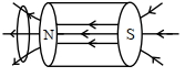
Consider a magnet surrounded by a wire loop with an on/off switch $S$ as shown in the figure. If the switch is thrown from the off position (open circuit) to the on position (closed circuit), will a current flow in the circuit? Explain.
Solution
(N/A) No, a current will not flow in the circuit.
According to Faraday's law of electromagnetic induction, an induced electromotive force $(EMF)$ and consequently an induced current are produced only when there is a change in the magnetic flux linked with the coil.
In this scenario, the magnet is stationary relative to the wire loop. Even when the switch $S$ is closed, the magnetic field lines passing through the loop remain constant. Since there is no change in the magnetic flux $(\Delta \Phi = 0)$, no induced current is generated in the circuit.
0 likes
View Solution158
Easy
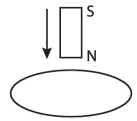
Consider a metal ring kept on top of a fixed solenoid (say on a cardboard) as per the figure. The center of the ring coincides with the axis of the solenoid. If the current is suddenly switched on,the metal ring jumps up. Explain.

Solution
(N/A) Initially,there is no magnetic flux linked with the metal ring.
When the current is suddenly switched on,the magnetic field produced by the solenoid increases rapidly.
According to Faraday's law of electromagnetic induction,this change in magnetic flux induces an electromotive force $(EMF)$ and consequently an induced current in the metal ring.
According to Lenz's law,the direction of this induced current is such that it opposes the cause that produced it,which is the increasing magnetic flux.
Therefore,the induced current in the ring flows in a direction opposite to the current in the solenoid.
Due to this,the ring and the solenoid act like two magnets with like poles facing each other,resulting in a repulsive force.
This repulsive force causes the metal ring to jump up.
0 likes
View Solution159
Easy
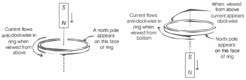
Consider a metal ring kept (supported by a cardboard) on top of a fixed solenoid carrying a current $I$ as per the figure. The centre of the ring coincides with the axis of the solenoid. If the current in the solenoid is switched off,what will happen to the ring?
Solution
(N/A) When the current in the solenoid is switched off,the magnetic flux linked with the metal ring decreases.
According to Lenz's Law,the induced current in the ring will flow in such a direction as to oppose this decrease in magnetic flux.
This means the ring will develop a magnetic polarity that attracts it towards the solenoid.
Therefore,the ring will remain on the cardboard and will not move away.
According to Lenz's Law,the induced current in the ring will flow in such a direction as to oppose this decrease in magnetic flux.
This means the ring will develop a magnetic polarity that attracts it towards the solenoid.
Therefore,the ring will remain on the cardboard and will not move away.
0 likes
View Solution160
Difficult
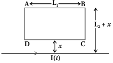
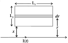
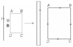
$A$ rectangular loop of wire $ABCD$ is kept close to an infinitely long wire carrying a current $I(t) = I_0(1 - t/T)$ for $0 \le t \le T$ and $I(t) = 0$ for $t > T$ as shown in the figure. Find the total charge passing through a given point in the loop in time $T$. The resistance of the loop is $R$.
Solution
(N/A) The magnetic field $B$ at a distance $r$ from an infinitely long wire carrying current $I$ is $B = \frac{\mu_0 I}{2 \pi r}$.
Consider a strip of thickness $dr$ and length $L_1$ at a distance $r$ from the wire.
The magnetic flux $d\phi$ linked with this strip is $d\phi = B \cdot dA = \frac{\mu_0 I}{2 \pi r} (L_1 dr)$.
The total magnetic flux $\phi$ linked with the rectangular loop $ABCD$ is the integral of $d\phi$ from $r = x$ to $r = x + L_2$:
$\phi = \int_{x}^{x+L_2} \frac{\mu_0 I L_1}{2 \pi r} dr = \frac{\mu_0 I L_1}{2 \pi} [\ln r]_{x}^{x+L_2} = \frac{\mu_0 I L_1}{2 \pi} \ln \left( \frac{x + L_2}{x} \right)$.
The induced current is $i = \frac{|d\phi/dt|}{R}$. The total charge $Q$ passing through a point is $Q = \int i dt = \frac{1}{R} \int |d\phi| = \frac{|\Delta \phi|}{R}$.
At $t = 0$,$I(0) = I_0$,so $\phi_i = \frac{\mu_0 I_0 L_1}{2 \pi} \ln \left( \frac{x + L_2}{x} \right)$.
At $t = T$,$I(T) = 0$,so $\phi_f = 0$.
The magnitude of the change in flux is $|\Delta \phi| = |\phi_f - \phi_i| = \frac{\mu_0 I_0 L_1}{2 \pi} \ln \left( \frac{x + L_2}{x} \right)$.
Therefore,the total charge $Q$ is $\frac{\mu_0 I_0 L_1}{2 \pi R} \ln \left( 1 + \frac{L_2}{x} \right)$.
0 likes
View Solution161
Difficult
$A$ magnetic field $B$ is confined to a region $r \le a$ and points out of the paper (the $z$-axis),$r = 0$ being the centre of the circular region. $A$ charged ring (charge $= Q$) of radius $b$,$b > a$ and mass $m$ lies in the $xy$-plane with its centre at the origin. The ring is free to rotate and is at rest. The magnetic field is brought to zero in time $\Delta t$. Find the angular velocity $\omega$ of the ring after the field vanishes.
Solution
(D) The change in magnetic flux $\Delta \phi$ through the ring is $\pi a^2 B$. According to Faraday's law,the induced electromotive force (emf) is $\varepsilon = \frac{\Delta \phi}{\Delta t} = \frac{B \pi a^2}{\Delta t}$.
This induced emf creates an induced electric field $E$ along the ring such that $\varepsilon = E(2 \pi b)$. Thus,$E = \frac{B a^2}{2 b \Delta t}$.
The force on the charge $Q$ is $F = QE = \frac{Q B a^2}{2 b \Delta t}$.
The torque $\tau$ acting on the ring is $\tau = F \cdot b = \frac{Q B a^2}{2 \Delta t}$.
Using the impulse-momentum theorem for rotation,$\tau \Delta t = \Delta L = I \omega$,where $I = m b^2$ is the moment of inertia of the ring.
Substituting the values: $\left( \frac{Q B a^2}{2 \Delta t} \right) \Delta t = m b^2 \omega$.
Therefore,$\omega = \frac{Q B a^2}{2 m b^2}$.
0 likes
View Solution162
MediumMCQ
The magnetic flux linked with a coil (in $Wb$) is given by the equation $\phi = 5t^2 + 3t + 16$. The magnitude of induced emf in the coil at the fourth second will be (in $V$):
A
$10$
B
$33$
C
$43$
D
$108$
Solution
(C) The magnitude of the induced emf $(\varepsilon)$ is given by Faraday's law of induction: $|\varepsilon| = |\frac{d\phi}{dt}|$.
Given the magnetic flux $\phi = 5t^2 + 3t + 16$.
Differentiating $\phi$ with respect to time $t$:
$\frac{d\phi}{dt} = \frac{d}{dt}(5t^2 + 3t + 16) = 10t + 3$.
To find the magnitude of the induced emf at the fourth second $(t = 4 \, s)$:
$|\varepsilon| = 10(4) + 3 = 40 + 3 = 43 \, V$.
Given the magnetic flux $\phi = 5t^2 + 3t + 16$.
Differentiating $\phi$ with respect to time $t$:
$\frac{d\phi}{dt} = \frac{d}{dt}(5t^2 + 3t + 16) = 10t + 3$.
To find the magnitude of the induced emf at the fourth second $(t = 4 \, s)$:
$|\varepsilon| = 10(4) + 3 = 40 + 3 = 43 \, V$.
0 likes
View Solution163
MediumMCQ
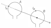
$A$ system $S$ consists of two coils $A$ and $B$. The coil $A$ carries a steady current $I$. The coil $B$ is suspended nearby as shown in the figure. If the system is heated,so as to raise the temperature of the two coils steadily,then:
A
The two coils show attraction.
B
The two coils show repulsion.
C
There is no change in the position of the two coils.
D
Induced current is not possible in coil $B$.
Solution
(A) When the system is heated,the resistance of the coils increases due to the rise in temperature.
Since the coil $A$ is connected to a source,the increase in its resistance causes the current $I$ in coil $A$ to decrease steadily.
According to Faraday's law of electromagnetic induction,a changing current in coil $A$ produces a changing magnetic flux through coil $B$.
This changing magnetic flux induces an electromotive force (emf) and consequently an induced current in coil $B$.
According to Lenz's law,the induced current in coil $B$ will flow in such a direction as to oppose the cause of its production,which is the decrease in current in coil $A$.
To oppose the decrease in current,the induced current in coil $B$ will flow in the same direction as the current in coil $A$.
Two parallel coils carrying currents in the same direction attract each other. Therefore,the two coils show attraction.
0 likes
View Solution164
DifficultMCQ
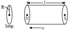
$A$ bar magnet is passing through a conducting loop of radius $R$ with velocity $v$. The radius of the bar magnet is such that it just passes through the loop. The induced $e.m.f.$ in the loop can be represented by the approximate curve:
A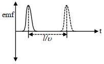
B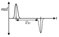
C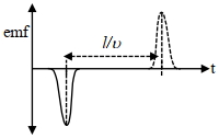
D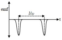
Solution
(B) According to Faraday's law of electromagnetic induction,the induced $e.m.f.$ is given by $\varepsilon = -\frac{d\phi}{dt}$.
$1$. As the north pole of the magnet approaches the loop,the magnetic flux through the loop increases. By Lenz's law,the induced current creates a magnetic field opposing this increase,resulting in a negative induced $e.m.f.$
$2$. When the magnet is completely inside the loop,the magnetic flux through the loop remains constant (assuming the magnet is long enough or the flux lines are parallel within the magnet),so $\frac{d\phi}{dt} = 0$,and the induced $e.m.f.$ is zero.
$3$. As the south pole of the magnet leaves the loop,the magnetic flux through the loop decreases. The induced current creates a magnetic field to oppose this decrease,resulting in a positive induced $e.m.f.$
Therefore,the graph shows a negative pulse followed by a positive pulse,which corresponds to Graph $B$.
0 likes
View Solution165
MediumMCQ
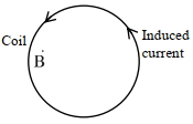
$A$ coil is placed in a magnetic field $\vec{B}$ as shown below. $A$ current is induced in the coil because $\vec{B}$ is:
A
Outward and decreasing with time
B
Parallel to the plane of coil and decreasing with time
C
Outward and increasing with time
D
Parallel to the plane of coil and increasing with time
Solution
(A) $1$. The magnetic flux through the coil is given by $\Phi = \vec{B} \cdot \vec{A} = BA \cos \theta$. For an induced current to exist,the magnetic flux must change with time.
$2$. If $\vec{B}$ is parallel to the plane of the coil,the angle $\theta = 90^\circ$,so $\Phi = 0$. Thus,options $B$ and $D$ are incorrect.
$3$. The induced current in the coil is in the anticlockwise direction. According to Lenz's Law,the induced magnetic field must oppose the change in flux.
$4$. If the external magnetic field $\vec{B}$ is directed outward (perpendicular to the plane of the coil),an anticlockwise induced current creates an inward magnetic field to oppose the change.
$5$. For the induced current to be anticlockwise,the outward flux must be decreasing so that the induced field acts to support the outward direction. Therefore,$\vec{B}$ must be outward and decreasing with time.
0 likes
View Solution166
MediumMCQ
The magnetic flux through a coil perpendicular to its plane is varying according to the relation $\phi = (5t^3 + 4t^2 + 2t - 5) \; Wb$. If the resistance of the coil is $5 \; \Omega$,then the induced current through the coil at $t = 2 \; s$ will be $.... \; A$. (in $.6$)
A
$15$
B
$16$
C
$17$
D
$18$
Solution
(A) The magnetic flux is given by $\phi = 5t^3 + 4t^2 + 2t - 5$.
According to Faraday's law of induction,the magnitude of the induced electromotive force $(EMF)$ is given by $|e| = |\frac{d\phi}{dt}|$.
Differentiating $\phi$ with respect to $t$:
$|e| = \frac{d}{dt}(5t^3 + 4t^2 + 2t - 5) = 15t^2 + 8t + 2$.
At $t = 2 \; s$,the induced $EMF$ is:
$|e| = 15(2)^2 + 8(2) + 2 = 15(4) + 16 + 2 = 60 + 16 + 2 = 78 \; V$.
The induced current $I$ is given by $I = \frac{|e|}{R}$,where $R = 5 \; \Omega$.
$I = \frac{78}{5} = 15.6 \; A$.
0 likes
View Solution167
MediumMCQ
Magnetic flux (in weber) in a closed circuit of resistance $20\,\Omega$ varies with time $t(s)$ as $\phi = 8t^2 - 9t + 5$. The magnitude of the induced current at $t = 0.25\,s$ will be $...mA$.
A
$249$
B
$248$
C
$247$
D
$250$
Solution
(D) Given magnetic flux $\phi = 8t^2 - 9t + 5$.
According to Faraday's law of induction,the induced $emf$ is given by $\varepsilon = -\frac{d\phi}{dt}$.
$\varepsilon = -\frac{d}{dt}(8t^2 - 9t + 5) = -(16t - 9) = 9 - 16t$.
At $t = 0.25\,s$,the induced $emf$ is $\varepsilon = 9 - 16(0.25) = 9 - 4 = 5\,V$.
The magnitude of the induced current $I$ is given by $I = \frac{|\varepsilon|}{R}$.
Given resistance $R = 20\,\Omega$,so $I = \frac{5\,V}{20\,\Omega} = 0.25\,A$.
Converting to milliamperes $(mA)$,$I = 0.25 \times 1000\,mA = 250\,mA$.
0 likes
View Solution168
MediumMCQ
In a coil of resistance $8 \, \Omega$,the magnetic flux due to an external magnetic field varies with time as $\phi = \frac{2}{3}(9 - t^2)$. The value of total heat produced in the coil,till the flux becomes zero,will be $.... \, J$.
A
$6$
B
$5$
C
$2$
D
$3$
Solution
(C) Given,$\phi = \frac{2}{3}(9 - t^2)$.
The flux becomes zero when $\phi = 0$,so $\frac{2}{3}(9 - t^2) = 0$,which gives $t^2 = 9$,or $t = 3 \, \text{s}$.
The induced electromotive force $(EMF)$ is given by Faraday's law: $e = -\frac{d\phi}{dt}$.
$e = -\frac{d}{dt} [\frac{2}{3}(9 - t^2)] = -\frac{2}{3}(0 - 2t) = \frac{4t}{3}$.
The heat produced $H$ in the coil is given by $H = \int_{0}^{t} \frac{e^2}{R} dt$.
Substituting the values $e = \frac{4t}{3}$ and $R = 8 \, \Omega$:
$H = \int_{0}^{3} \frac{(\frac{4t}{3})^2}{8} dt = \int_{0}^{3} \frac{16t^2}{9 \times 8} dt = \int_{0}^{3} \frac{2t^2}{9} dt$.
$H = \frac{2}{9} [\frac{t^3}{3}]_{0}^{3} = \frac{2}{9} \times \frac{27}{3} = \frac{2}{9} \times 9 = 2 \, \text{J}$.
0 likes
View Solution169
MediumMCQ
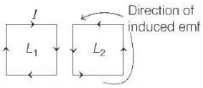
Two identical metallic square loops $L_1$ and $L_2$ are placed next to each other with their sides parallel on a smooth horizontal table. Loop $L_1$ is fixed and a current which increases as a function of time is passed through it. Then,loop $L_2$ is
A
rotates about its centre of mass
B
moves towards $L_1$
C
remains stationary
D
moves away from $L_1$
Solution
(D) According to Lenz's Law,the induced current in loop $L_2$ will oppose the change in magnetic flux linked with it.
As the current in loop $L_1$ increases with time,the magnetic flux linked with loop $L_2$ also increases.
To oppose this increase in flux,the induced current in loop $L_2$ flows in such a direction that the magnetic field produced by it opposes the magnetic field of $L_1$. This results in currents flowing in opposite directions in the adjacent arms of the two loops.
Since currents in the adjacent arms of $L_1$ and $L_2$ are in opposite directions,there is a repulsive force between them.
Consequently,loop $L_2$ moves away from loop $L_1$.
0 likes
View Solution170
MediumMCQ
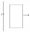
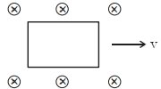
$A$ rectangular loop of wire is coplanar with a long wire carrying current $I$. The loop is pulled to the right as indicated. What are the directions of the induced current in the loop and the magnetic forces on the left and the right sides of the loop?
A
$a$. Counter clockwise,To the left,To the right
B
$b$. Clockwise,To the left,To the right
C
$c$. Counter clockwise,To the right,To the left
D
$d$. Clockwise,To the right,To the left
Solution
(B) The magnetic field $B$ produced by the long wire carrying current $I$ is directed into the page (inward) in the region of the loop. As the loop is pulled to the right,it moves into a region where the magnetic field strength decreases,thus the magnetic flux through the loop decreases.
According to Lenz's law,the induced current in the loop will flow in a direction to oppose this decrease in flux,which means it will create its own magnetic field directed into the page. By the right-hand rule,this corresponds to a clockwise induced current.
For the left side of the loop (closest to the wire),the current flows upward,which is in the same direction as the current $I$ in the long wire. Parallel currents attract,so the force on the left side is directed towards the long wire (to the left).
For the right side of the loop,the current flows downward,which is opposite to the current $I$ in the long wire. Anti-parallel currents repel,so the force on the right side is directed away from the long wire (to the right).
0 likes
View Solution171
MediumMCQ
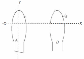
The diagram below shows two circular loops of wire ($A$ and $B$) centred on and perpendicular to the $X$-axis and oriented with their planes parallel to each other. The $Y$-axis passes vertically through loop $A$ (dashed line). There is a current $I_B$ in loop $B$ as shown in the diagram. Possible actions which we might perform on loop $A$ are:
$(I)$ move $A$ to the right along $X$-axis closer to $B$
$(II)$ move $A$ to the left along $X$-axis away from $B$
$(III)$ as viewed from above,rotate $A$ clockwise about $Y$-axis
$(IV)$ as viewed from above,rotate $A$ anti-clockwise about $Y$-axis
Which of the actions will induce a current in $A$ only in the direction shown?
A
Only $(I)$
B
Only $(II)$
C
Only $(I)$ and $(IV)$
D
Only $(II)$ and $(III)$
Solution
(C) The current $I_B$ in loop $B$ creates a magnetic field directed towards the left (through loop $A$).
According to Lenz's Law,the induced current in loop $A$ will oppose the change in magnetic flux through it.
If we move loop $A$ to the right (closer to $B$),the magnetic flux through $A$ increases. To oppose this increase,the induced current in $A$ will create a magnetic field to the right,which corresponds to an anti-clockwise current as viewed from the left.
If we rotate $A$ anti-clockwise about the $Y$-axis (as viewed from above),the angle between the area vector of $A$ and the magnetic field lines from $B$ changes such that the flux through $A$ increases,also inducing an anti-clockwise current.
Thus,both actions $(I)$ and $(IV)$ result in an increase in magnetic flux through $A$,inducing the current in the desired direction.
0 likes
View Solution172
MediumMCQ
$A$ bar magnet falls with its north pole pointing down through the axis of a copper ring. When viewed from above,the current in the ring will be
A
clockwise,while the magnet is above the plane of the ring and counter clockwise,while below the plane of the ring
B
counter clockwise throughout
C
counter clockwise,while the magnet is above the plane of the ring and clockwise,while below the plane of the ring
D
clockwise throughout
Solution
(C) According to Lenz's law,the direction of the induced current is such that it opposes the change in magnetic flux that produced it.
$1$. When the magnet is above the ring and falling towards it,the magnetic flux through the ring increases. To oppose this,the ring develops a north pole on its upper face to repel the falling magnet. $A$ north pole corresponds to a counter-clockwise current when viewed from above.
$2$. When the magnet passes through the ring and moves away below it,the magnetic flux through the ring decreases. To oppose this decrease,the ring develops a south pole on its lower face (which acts as a north pole on its upper face relative to the receding magnet) to attract the magnet. This corresponds to a clockwise current when viewed from above.
Therefore,the current is counter-clockwise while the magnet is above the ring and clockwise while it is below the ring.
0 likes
View Solution173
MediumMCQ
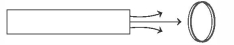
The figure shows a bar magnet and a metallic coil. Consider four situations:
$(I)$ Moving the magnet away from the coil.
$(II)$ Moving the coil towards the magnet.
$(III)$ Rotating the coil about the vertical diameter.
$(IV)$ Rotating the coil about its axis.
An emf in the coil will be generated for the following situations.
$(I)$ Moving the magnet away from the coil.
$(II)$ Moving the coil towards the magnet.
$(III)$ Rotating the coil about the vertical diameter.
$(IV)$ Rotating the coil about its axis.
An emf in the coil will be generated for the following situations.
A
$I$ and $II$ only
B
$I, II$ and $IV$ only
C
$I, II,$ and $III$ only
D
$I, II, III,$ and $IV$
Solution
(C) According to Faraday's law of electromagnetic induction, an electromotive force (emf) is induced in a coil whenever there is a change in the magnetic flux linked with the coil.
$(I)$ Moving the magnet away from the coil changes the magnetic flux through the coil, thus inducing an emf.
$(II)$ Moving the coil towards the magnet also changes the magnetic flux through the coil, thus inducing an emf.
$(III)$ Rotating the coil about its vertical diameter changes the angle between the area vector of the coil and the magnetic field lines, which changes the magnetic flux $(\Phi = B A \cos \theta)$. This change in flux induces an emf.
$(IV)$ Rotating the coil about its own axis does not change the magnetic flux linked with the coil because the orientation of the coil relative to the magnetic field lines remains constant. Therefore, no emf is induced in this case.
Thus, an emf is generated in situations $(I), (II),$ and $(III)$ only.
0 likes
View Solution174
DifficultMCQ
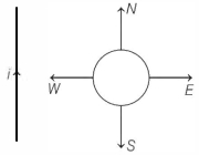
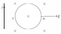
$A$ circular loop of wire is in the same plane as an infinitely long wire carrying a constant current $i$. Four possible motions of the loop are marked by $N, E, W$,and $S$ as shown below. $A$ clockwise current is induced in the loop when the loop is pulled towards:
A
$N$
B
$E$
C
$W$
D
$S$
Solution
(B) The magnetic field produced by the long wire carrying current $i$ is directed into the plane of the paper (inward) at the location of the loop.
According to Lenz's law,the induced current in the loop will oppose the change in magnetic flux linked with it.
For a clockwise current to be induced in the loop,the magnetic flux through the loop must decrease (as per the right-hand rule,a clockwise current produces an inward magnetic field,which would oppose a decrease in the existing inward flux).
The magnetic flux linked with the loop decreases when the loop is moved away from the current-carrying wire.
Looking at the diagram,moving the loop in the direction $E$ (East) increases the distance from the wire,thereby decreasing the magnetic flux through the loop. Thus,a clockwise current is induced when the loop is pulled towards $E$.
0 likes
View Solution175
EasyMCQ
$A$ circular loop of flexible conducting material is kept in a magnetic field directed perpendicularly into its plane. By holding the loop at diametrically opposite points,it is suddenly stretched outwards,then
A
No current is induced in the loop
B
Anti-clockwise current is induced
C
Clockwise current is induced
D
Only e.m.f. is induced
Solution
(B) The magnetic flux $\phi$ through the loop is given by $\phi = B \cdot A$,where $B$ is the magnetic field and $A$ is the area of the loop.
When the loop is stretched outwards,its area $A$ increases.
Since the magnetic field $B$ is directed into the plane,the magnetic flux through the loop increases.
According to Lenz's Law,the induced current will flow in a direction that opposes this increase in magnetic flux.
To oppose the increase in inward magnetic flux,the induced magnetic field must be directed outwards.
By the right-hand thumb rule,a current flowing in a clockwise direction produces a magnetic field directed into the plane,while a counter-clockwise current produces a field directed outwards.
Wait,let us re-evaluate: If the flux is directed into the plane and is increasing,the induced current must create a magnetic field directed out of the plane to oppose the change.
Therefore,the induced current must be anti-clockwise.
Correction: Re-checking the standard convention,if the area increases,the flux into the plane increases. To oppose this,the induced current must create a field out of the plane,which is anti-clockwise. However,if the loop is stretched,the flux increases. Lenz's law states the induced current opposes the change. Thus,the correct answer is $(b)$.
0 likes
View Solution176
EasyMCQ
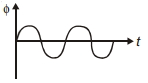
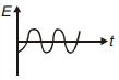
The magnetic flux $\phi$ through a coil varies with time $t$ as shown in the diagram. Which graph best represents the variation of the induced electromotive force (e.m.f.) $E$ in the coil with time $t$?
A
B
C
D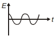
Solution
(D) According to Faraday's law of electromagnetic induction,the induced e.m.f. $E$ is given by the negative rate of change of magnetic flux $\phi$ with respect to time $t$:
$E = -\frac{d\phi}{dt}$
From the given diagram,the magnetic flux $\phi$ varies sinusoidally with time $t$,which can be represented as:
$\phi = \phi_0 \sin(\omega t)$
Now,differentiating this expression with respect to time $t$ to find the induced e.m.f. $E$:
$E = -\frac{d}{dt} [\phi_0 \sin(\omega t)]$
$E = -\phi_0 \omega \cos(\omega t)$
Using the trigonometric identity $-\cos(\theta) = \sin(\theta - \frac{\pi}{2})$,we get:
$E = \phi_0 \omega \sin(\omega t - \frac{\pi}{2})$
This shows that the induced e.m.f. $E$ also varies sinusoidally with time $t$,but it has a phase shift of $-\frac{\pi}{2}$ relative to the magnetic flux $\phi$. At $t = 0$,the flux $\phi = 0$,while the induced e.m.f. $E = -\phi_0 \omega$,which is a negative maximum value. Among the given options,the graph that starts at a negative maximum value and follows a sinusoidal pattern is represented by option $(D)$.
0 likes
View Solution177
EasyMCQ
When a conducting wire $XY$ is moved towards the right,a current flows in the anti-clockwise direction in the loop. The direction of the magnetic field at point $O$ is

A
Parallel to the motion of the wire
B
Along $XY$
C
Perpendicular,pointing out of the paper
D
Perpendicular,pointing into the paper
Solution
(C) According to Lenz's law,the induced current in a loop always opposes the change in magnetic flux that produces it.
When the conducting wire $XY$ moves to the right,the area of the loop increases,which increases the magnetic flux through the loop.
To oppose this increase in flux,the induced current must create a magnetic field that opposes the existing magnetic field.
Given that the induced current flows in the anti-clockwise direction,we can use the Right-Hand Thumb Rule. By curling the fingers of the right hand in the direction of the current (anti-clockwise),the thumb points outwards,perpendicular to the plane of the paper.
Therefore,the direction of the magnetic field at point $O$ is perpendicular to the paper and pointing outwards.
0 likes
View Solution178
EasyMCQ
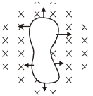
$A$ loop of irregular shape of conducting wire (as shown in the figure) is placed in a uniform magnetic field perpendicular to the plane of the paper. If the loop changes into a circular shape,the direction of the induced current will be:
A
Clockwise
B
Anti-clockwise
C
No current
D
None of these
Solution
(B) $1$. The magnetic field is uniform and directed into the plane of the paper (represented by crosses).
$2$. As the irregular loop expands to become a circular shape,the area enclosed by the loop increases.
$3$. Since the magnetic field is constant,an increase in the area leads to an increase in the magnetic flux linked with the loop.
$4$. According to Lenz's law,the induced current will flow in a direction that opposes this increase in magnetic flux.
$5$. To oppose the inward magnetic flux,the induced current must create an outward magnetic field.
$6$. By the right-hand thumb rule,an outward magnetic field is produced by an anti-clockwise current.
$7$. Therefore,the direction of the induced current is anti-clockwise.
0 likes
View Solution179
EasyMCQ
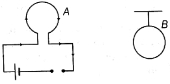
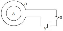
What will be the direction of current in the coil $A$ as the switch $S$ is closed?
A
Clockwise
B
Anticlockwise
C
Anticlockwise and then clockwise
D
Clockwise and then anticlockwise
Solution
(B) When the switch $S$ is closed,current starts flowing in the outer coil $B$. Based on the battery polarity shown in the diagram,the current in coil $B$ flows in a clockwise direction.
As the current in coil $B$ increases from zero to its steady value,the magnetic flux linked with the inner coil $A$ increases in the inward direction (perpendicular to the plane of the coil).
According to Lenz's law,the induced current in coil $A$ will oppose this increase in magnetic flux by creating its own magnetic field in the outward direction.
To produce an outward magnetic field,the induced current in coil $A$ must flow in an anticlockwise direction.
0 likes
View Solution180
EasyMCQ
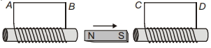
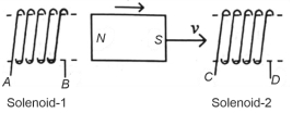
$A$ magnet is moved in the direction indicated by an arrow between two coils $AB$ and $CD$ as shown in the figure. The direction of the induced current in the coils is
A
$A$ to $B$ and $C$ to $D$
B
$B$ to $A$ and $C$ to $D$
C
$A$ to $B$ and $D$ to $C$
D
$B$ to $A$ and $D$ to $C$
Solution
(C) According to Lenz's law,the direction of the induced current is such that it opposes the change in magnetic flux that produced it.
$1$. For coil $AB$: The North pole $(N)$ of the magnet is moving away from coil $AB$. To oppose this,the face of the coil near the magnet must act as a South pole $(S)$. This requires the current to flow in a clockwise direction when viewed from the magnet's side,which corresponds to the current flowing from $A$ to $B$ in the wire.
$2$. For coil $CD$: The South pole $(S)$ of the magnet is moving towards coil $CD$. To oppose this,the face of the coil near the magnet must act as a South pole $(S)$. This requires the current to flow in a clockwise direction when viewed from the magnet's side,which corresponds to the current flowing from $D$ to $C$ in the wire.
Therefore,the induced current flows from $A$ to $B$ and $D$ to $C$.
0 likes
View Solution181
MediumMCQ
$A$ coil with $10$ turns and a resistance of $20\,\Omega$ is connected in series with a ballistic galvanometer ($B$.$G$.) of resistance $30\,\Omega$. The coil is placed with its plane perpendicular to the direction of a uniform magnetic field of induction $10^{-2}\,T$. If it is now turned through an angle of $60^{\circ}$ about an axis in its plane, find the charge induced in the coil $..............\times 10^{-5} \, C$ (Area of the coil $= 10^{-2}\,m^2$).
A
$2$
B
$3.2$
C
$1$
D
$5.5$
Solution
(C) Given: Number of turns $n = 10$, resistance of coil $R_{\text{coil}} = 20\,\Omega$, resistance of $B$.$G$. $R_G = 30\,\Omega$.
Total resistance in the circuit $R = R_{\text{coil}} + R_G = 20 + 30 = 50\,\Omega$.
Area of the coil $A = 10^{-2}\,m^2$, magnetic field $B = 10^{-2}\,T$.
Initial angle between the area vector and the magnetic field $\theta_1 = 0^{\circ}$.
Final angle between the area vector and the magnetic field $\theta_2 = 60^{\circ}$.
The induced charge $q$ is given by $q = \frac{\Delta \phi}{R} = \frac{nAB(\cos \theta_1 - \cos \theta_2)}{R}$.
Substituting the values: $q = \frac{10 \times 10^{-2} \times 10^{-2} \times (\cos 0^{\circ} - \cos 60^{\circ})}{50}$.
$q = \frac{10^{-3} \times (1 - 0.5)}{50} = \frac{10^{-3} \times 0.5}{50} = \frac{0.5 \times 10^{-3}}{50} = 0.01 \times 10^{-3} = 1 \times 10^{-5}\,C$.
Thus, the charge induced is $1 \times 10^{-5}\,C$.
0 likes
View Solution182
EasyMCQ
$A$ coil of resistance $400\,\Omega$ is placed in a magnetic field. If the magnetic flux $\phi$ (in $Wb$) linked with the coil varies with time $t$ (in $s$) as $\phi = 50t^2 + 4$,the current in the coil at $t = 2\,s$ is $..........\,A$.
A
$0.5$
B
$0.1$
C
$2$
D
$1$
Solution
(A) According to Faraday's law of electromagnetic induction,the induced electromotive force (e.m.f.) $\varepsilon$ is given by $\varepsilon = -\frac{d\phi}{dt}$.
Given $\phi = 50t^2 + 4$,we differentiate with respect to $t$:
$\frac{d\phi}{dt} = \frac{d}{dt}(50t^2 + 4) = 100t$.
Thus,the magnitude of the induced e.m.f. is $|\varepsilon| = |-\frac{d\phi}{dt}| = 100t$.
At $t = 2\,s$,the induced e.m.f. is $|\varepsilon| = 100 \times 2 = 200\,V$.
The induced current $i$ is given by $i = \frac{|\varepsilon|}{R}$,where $R = 400\,\Omega$.
Therefore,$i = \frac{200}{400} = 0.5\,A$.
0 likes
View Solution183
MediumMCQ
Assertion $(A):$ The bar magnet falling vertically along the axis of the horizontal coil will have an acceleration less than $g$.
Reason $(R):$ Clockwise current is induced in the coil.
Reason $(R):$ Clockwise current is induced in the coil.
A
If both Assertion and Reason are true and Reason is the correct explanation of Assertion.
B
If both Assertion and Reason are true but Reason is not the correct explanation of Assertion.
C
If Assertion is true but Reason is false.
D
If both Assertion and Reason are false.
Solution
(C) According to Lenz's Law,when the north pole of a bar magnet falls towards a horizontal coil,the magnetic flux linked with the coil increases. To oppose this increase,the coil induces a current such that the upper face of the coil acts as a north pole.
This induced north pole repels the falling north pole of the magnet,creating an upward repulsive force. This force opposes the downward gravitational force,resulting in a net downward acceleration $a < g$.
Since the upper face of the coil acts as a north pole,the current induced in the coil must be counter-clockwise (as viewed from above),not clockwise. Therefore,the Assertion is true,but the Reason is false.
0 likes
View Solution184
MediumMCQ
$A$ conducting loop of radius $\frac{10}{\sqrt{\pi}}\,cm$ is placed perpendicular to a uniform magnetic field of $0.5\,T$. The magnetic field is decreased to $zero$ in $0.5\,s$ at a steady rate. The induced emf in the circular loop at $0.25\,s$ is:
A
$emf = 1\,mV$
B
$emf = 10\,mV$
C
$emf = 100\,mV$
D
$emf = 5\,mV$
Solution
(B) The radius of the loop is $r = \frac{10}{\sqrt{\pi}}\,cm = \frac{0.1}{\sqrt{\pi}}\,m$.
The area of the loop is $A = \pi r^2 = \pi \left( \frac{0.1}{\sqrt{\pi}} \right)^2 = \pi \left( \frac{0.01}{\pi} \right) = 0.01\,m^2$.
The magnetic field changes from $B_i = 0.5\,T$ to $B_f = 0\,T$ in time $\Delta t = 0.5\,s$.
The rate of change of magnetic field is $\frac{dB}{dt} = \frac{0.5 - 0}{0.5} = 1\,T/s$.
According to Faraday's law,the induced emf is $\varepsilon = -\frac{d\phi}{dt} = -A \frac{dB}{dt}$.
Substituting the values,$|\varepsilon| = (0.01\,m^2) \times (1\,T/s) = 0.01\,V$.
Converting to millivolts,$|\varepsilon| = 0.01 \times 1000\,mV = 10\,mV$.
0 likes
View Solution185
EasyMCQ
The magnetic flux linked to a circular coil of radius $R$ is given by $\phi = 2t^3 + 4t^2 + 2t + 5 \; Wb$. The magnitude of the induced $emf$ in the coil at $t = 5 \; s$ is $.......... \; V$.
A
$108$
B
$197$
C
$150$
D
$192$
Solution
(D) The magnetic flux is given by $\phi = 2t^3 + 4t^2 + 2t + 5$.
According to Faraday's law of electromagnetic induction,the induced $emf$ $(e)$ is given by the magnitude of the rate of change of magnetic flux:
$e = |\frac{d\phi}{dt}|$
$e = |\frac{d}{dt}(2t^3 + 4t^2 + 2t + 5)|$
$e = |6t^2 + 8t + 2|$
Now,substitute $t = 5 \; s$ into the expression for $e$:
$e = 6(5)^2 + 8(5) + 2$
$e = 6(25) + 40 + 2$
$e = 150 + 40 + 2 = 192 \; V$.
Thus,the magnitude of the induced $emf$ at $t = 5 \; s$ is $192 \; V$.
1 likes
View Solution186
MediumMCQ
The induced $emf$ can be produced in a coil by:
$A.$ Moving the coil with uniform speed inside a magnetic field.
$B.$ Moving the coil with non-uniform speed inside a uniform magnetic field.
$C.$ Rotating the coil inside a uniform magnetic field.
$D.$ Changing the area of the coil inside a uniform magnetic field.
Choose the correct answer from the options given below:
A
$B$ and $D$ only
B
$B$ and $C$ only
C
$A$ and $C$ only
D
$C$ and $D$ only
Solution
(D) According to Faraday's law of electromagnetic induction,an induced $emf$ is produced in a coil whenever the magnetic flux linked with the coil changes with time $(\varepsilon = -d\Phi_B / dt)$.
$A.$ Moving a coil with uniform speed inside a uniform magnetic field does not change the magnetic flux $(\Phi_B = B \cdot A \cdot \cos \theta)$,so no $emf$ is induced.
$B.$ Moving a coil with non-uniform speed inside a uniform magnetic field also does not change the magnetic flux,so no $emf$ is induced.
$C.$ Rotating the coil inside a uniform magnetic field changes the angle $\theta$ between the area vector and the magnetic field,thus changing the magnetic flux and inducing an $emf$.
$D.$ Changing the area of the coil inside a uniform magnetic field changes the magnetic flux,thus inducing an $emf$.
Therefore,both $C$ and $D$ result in an induced $emf$.
0 likes
View Solution187
DifficultMCQ
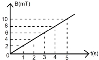
The magnetic field $B$ crossing normally a square metallic plate of area $4\,m^2$ changes with time as shown in the figure. The magnitude of the induced $emf$ in the plate during $t=2\,s$ to $t=4\,s$ is $..........\,mV$.
A
$5$
B
$8$
C
$6$
D
$7$
Solution
(B) The magnetic flux $\phi$ through the plate is given by $\phi = B \cdot A$, where $A = 4\,m^2$ is the area and $B$ is the magnetic field.
From the graph, the magnetic field $B$ is a linear function of time $t$ (in seconds) with $B$ in $mT$ (milliTesla).
The slope of the line is $m = \frac{dB}{dt} = \frac{10\,mT - 0\,mT}{5\,s - 0\,s} = 2\,mT/s$.
According to Faraday's law of induction, the magnitude of the induced $emf$ $(\varepsilon)$ is given by $\varepsilon = \left| \frac{d\phi}{dt} \right| = A \left| \frac{dB}{dt} \right|$.
Substituting the values: $\varepsilon = 4\,m^2 \times 2\,mT/s = 8\,mV$.
Thus, the magnitude of the induced $emf$ is $8\,mV$.
0 likes
View Solution188
MediumMCQ
An insulated copper wire of $100$ turns is wrapped around a wooden cylindrical core of the cross-sectional area $24\,cm^2$. The two ends of the wire are connected to a resistor. The total resistance in the circuit is $12\,\Omega$. If an externally applied uniform magnetic field in the core along its axis changes from $1.5\,T$ in one direction to $1.5\,T$ in the opposite direction,the charge flowing through a point in the circuit during the change of magnetic field will be $.........\,mC$.
A
$50$
B
$60$
C
$40$
D
$30$
Solution
(B) The change in magnetic flux $\Delta \phi$ is given by $\Delta \phi = N A (B_2 - B_1)$.
Given: $N = 100$,$A = 24\,cm^2 = 24 \times 10^{-4}\,m^2$,$R = 12\,\Omega$,$B_1 = 1.5\,T$,and $B_2 = -1.5\,T$.
Thus,$\Delta \phi = 100 \times 24 \times 10^{-4} \times (-1.5 - 1.5) = 0.24 \times (-3) = -0.72\,Wb$.
The induced charge $Q$ is given by $Q = \frac{|\Delta \phi|}{R}$.
$Q = \frac{0.72}{12} = 0.06\,C$.
Converting to $mC$: $0.06\,C = 60\,mC$.
0 likes
View Solution189
DifficultMCQ
$A$ rectangular loop of length $2.5 \ m$ and width $2 \ m$ is placed at $60^{\circ}$ to a magnetic field of $4 \ T$. The loop is removed from the field in $10 \ s$. The average emf induced in the loop during this time is
A
$-2 \ V$
B
$+2 \ V$
C
$+1 \ V$
D
$-1 \ V$
Solution
(C) The magnetic flux $\phi$ through the loop is given by $\phi = B A \cos \theta$,where $\theta$ is the angle between the magnetic field vector and the area vector.
Given,the loop is placed at $60^{\circ}$ to the magnetic field,so the angle between the area vector and the magnetic field is $\theta = 90^{\circ} - 60^{\circ} = 30^{\circ}$.
Initial flux $\phi_i = B A \cos 30^{\circ} = 4 \times (2.5 \times 2) \times \frac{\sqrt{3}}{2} = 10\sqrt{3} \ Wb$.
However,standard interpretation of 'placed at $60^{\circ}$ to the field' often implies $\theta = 60^{\circ}$ as the angle between the normal and the field. Using $\phi = B A \cos 60^{\circ}$:
$\phi_i = 4 \times 5 \times 0.5 = 10 \ Wb$.
Final flux $\phi_f = 0 \ Wb$ (as the loop is removed from the field).
Average induced emf $\varepsilon = -\frac{\Delta \phi}{\Delta t} = -\frac{\phi_f - \phi_i}{\Delta t} = -\frac{0 - 10}{10} = +1 \ V$.
0 likes
View Solution190
DifficultMCQ
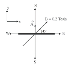
$A$ square loop of side $10 \ cm$ and resistance $0.7 \ \Omega$ is placed vertically in the east-west plane. $A$ uniform magnetic field of $0.20 \ T$ is set up across the plane in the north-east direction. The magnetic field is decreased to zero in $1 \ s$ at a steady rate. Then,the magnitude of the induced emf is $\sqrt{x} \times 10^{-3} \ V$. The value of $x$ is . . . . . . .
A
$1$
B
$11$
C
$2$
D
$3$
Solution
(C) The area vector $\vec{A}$ of the loop is perpendicular to the east-west plane,which is in the north-south direction. Let the north direction be $\hat{j}$. Thus,$\vec{A} = (0.1 \ m)^2 \hat{j} = 0.01 \hat{j} \ m^2$.
The magnetic field $\vec{B}$ is in the north-east direction,making an angle of $45^\circ$ with the east (horizontal) and north (vertical) axes. Thus,$\vec{B} = 0.20 (\cos 45^\circ \hat{i} + \sin 45^\circ \hat{j}) = 0.20 (\frac{1}{\sqrt{2}} \hat{i} + \frac{1}{\sqrt{2}} \hat{j}) \ T$.
The magnetic flux $\phi$ through the loop is $\phi = \vec{B} \cdot \vec{A} = [0.20 (\frac{1}{\sqrt{2}} \hat{i} + \frac{1}{\sqrt{2}} \hat{j})] \cdot [0.01 \hat{j}] = 0.20 \times 0.01 \times \frac{1}{\sqrt{2}} = \frac{0.002}{\sqrt{2}} = \sqrt{2} \times 10^{-3} \ Wb$.
The induced emf $e$ is given by $|e| = |\frac{\Delta \phi}{\Delta t}| = |\frac{0 - \phi}{1 \ s}| = \sqrt{2} \times 10^{-3} \ V$.
Comparing this with $\sqrt{x} \times 10^{-3} \ V$,we get $\sqrt{x} = \sqrt{2}$,which implies $x = 2$.
0 likes
View Solution191
DifficultMCQ
$A$ coil is placed perpendicular to a magnetic field of $5000 \,T$. When the field is changed to $3000 \,T$ in $2 \,s$, an induced emf of $22 \,V$ is produced in the coil. If the diameter of the coil is $0.02 \,m$, then the number of turns in the coil is:
A
$70$
B
$7$
C
$35$
D
$140$
Solution
(A) According to Faraday's law of electromagnetic induction, the induced emf $\varepsilon$ is given by $\varepsilon = N \left| \frac{\Delta \phi}{\Delta t} \right|$.
Here, $\Delta \phi = (\Delta B) A$, where $A = \pi r^2$ is the area of the coil.
Given: $B_i = 5000 \,T$, $B_f = 3000 \,T$, $\Delta t = 2 \,s$, $\varepsilon = 22 \,V$, and diameter $d = 0.02 \,m$.
The radius $r = \frac{d}{2} = 0.01 \,m$.
The change in magnetic field $\Delta B = |B_f - B_i| = |3000 - 5000| = 2000 \,T$.
The area $A = \pi (0.01)^2 = 0.0001 \pi \,m^2$.
The change in flux $\Delta \phi = (\Delta B) A = 2000 \times 0.0001 \pi = 0.2 \pi \,Wb$.
Substituting these values into the emf formula: $22 = N \left( \frac{0.2 \pi}{2} \right)$.
$22 = N (0.1 \pi)$.
Using $\pi \approx 3.14$, $22 = N (0.314) \Rightarrow N = \frac{22}{0.314} \approx 70$.
Thus, the number of turns is $70$.
0 likes
View Solution192
DifficultMCQ
The magnetic flux $\phi$ (in weber) linked with a closed circuit of resistance $8 \ \Omega$ varies with time (in seconds) as $\phi = 5t^2 - 36t + 1$. The induced current in the circuit at $t = 2 \ s$ is . . . . . . $A$.
A
$3$
B
$5$
C
$2$
D
$4$
Solution
(C) According to Faraday's law of electromagnetic induction,the induced electromotive force $(EMF)$ $\varepsilon$ is given by $\varepsilon = -\frac{d\phi}{dt}$.
Given $\phi = 5t^2 - 36t + 1$.
Differentiating with respect to $t$,we get $\frac{d\phi}{dt} = 10t - 36$.
Thus,$\varepsilon = -(10t - 36) = 36 - 10t$.
At $t = 2 \ s$,the induced $EMF$ is $\varepsilon = 36 - 10(2) = 36 - 20 = 16 \ V$.
The induced current $i$ is given by $i = \frac{|\varepsilon|}{R}$,where $R = 8 \ \Omega$.
Therefore,$i = \frac{16 \ V}{8 \ \Omega} = 2 \ A$.
0 likes
View Solution193
MediumMCQ
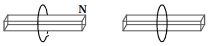
In the above diagram,a strong bar magnet is moving towards solenoid-$2$ from solenoid-$1$. The direction of induced current in solenoid-$1$ and that in solenoid-$2$,respectively,are through the directions:
A
$B A$ and $C D$
B
$A B$ and $C D$
C
$B A$ and $D C$
D
$A B$ and $D C$
Solution
(A) According to Lenz's Law,the induced current in a coil opposes the change in magnetic flux that produces it.
For solenoid-$1$: The North pole of the magnet is moving away from it. To oppose this,the end $B$ of solenoid-$1$ must act as a South pole. Using the right-hand thumb rule,the current flows from $B$ to $A$.
For solenoid-$2$: The South pole of the magnet is approaching it. To oppose this,the end $C$ of solenoid-$2$ must act as a South pole. Using the right-hand thumb rule,the current flows from $C$ to $D$.
Therefore,the directions of induced current are $B A$ and $C D$ respectively.
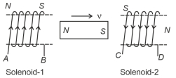
0 likes
View Solution194
DifficultMCQ
The figure shows certain wire segments joined together to form a coplanar loop. The loop is placed in a perpendicular magnetic field in the direction going into the plane of the figure. The magnitude of the field increases with time. $I_1$ and $I_2$ are the currents in the segments $ab$ and $cd$. Then,
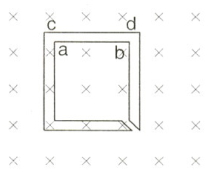
A
$I_1 > I_2$
B
$I_1 < I_2$
C
$I_1$ is in the direction $ba$ and $I_2$ is in the direction $ed$
D
$I_1$ is in the direction $ab$ and $I_2$ is in the direction $de$
Solution
(C) According to Lenz's law,the induced current will oppose the change in magnetic flux.
The magnetic field is directed into the plane of the paper and its magnitude is increasing with time,so the magnetic flux through the loop is increasing into the plane.
To oppose this increase,the induced magnetic field must be directed out of the plane of the paper.
Using the right-hand thumb rule,an induced magnetic field directed out of the plane corresponds to an anticlockwise induced current in the loop.
Following the anticlockwise path in the loop,the current flows from $b$ to $a$ in segment $ab$ and from $c$ to $d$ in segment $cd$ (or $d$ to $c$ depending on the specific loop geometry shown).
Looking at the provided options and the loop structure,the current flows in an anticlockwise direction. Thus,in segment $ab$,the current is from $b$ to $a$,and in segment $cd$,the current is from $c$ to $d$. Since the question asks for the direction,and based on the standard interpretation of such problems,the correct choice is that the current flows anticlockwise.
0 likes
View Solution195
DifficultMCQ
$A$ current-carrying infinitely long wire is kept along the diameter of a circular wire loop,without touching it. The correct statement$(s)$ is (are):
$(A)$ The emf induced in the loop is zero if the current is constant.
$(B)$ The emf induced in the loop is finite if the current is constant.
$(C)$ The emf induced in the loop is zero if the current decreases at a steady rate.
$(D)$ The emf induced in the loop is finite if the current decreases at a steady rate.
A
$(A, C)$
B
$(B, D)$
C
$(B, C)$
D
$(A, D)$
Solution
(A) The magnetic field lines produced by the infinitely long straight wire are circular and centered on the wire.
For any point above the wire,the magnetic field points out of the plane of the loop,and for any point below the wire,the magnetic field points into the plane of the loop.
Due to the symmetry of the circular loop about the diameter (the wire),the magnetic flux through the upper half of the loop is equal in magnitude but opposite in direction to the magnetic flux through the lower half of the loop.
Therefore,the net magnetic flux $(\phi)$ through the entire loop is always zero,regardless of the current $i$ flowing through the wire.
Since the induced emf $\varepsilon = -\frac{d\phi}{dt}$,and $\phi = 0$ at all times,the induced emf is zero regardless of whether the current is constant or changing.
Thus,statements $(A)$ and $(C)$ are correct.
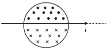
0 likes
View Solution196
EasyMCQ
$A$ conducting loop is kept perpendicularly in an increasing magnetic field,as shown in the figure. The direction of the induced current in the loop will be:
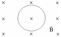
A
clockwise
B
anti-clockwise
C
zero
D
insufficient information
Solution
(B) According to Faraday's law of electromagnetic induction,a change in magnetic flux through a loop induces an $EMF$.
Lenz's law states that the direction of the induced current is such that it opposes the change in magnetic flux that produced it.
In the given figure,the magnetic field $\vec{B}$ is directed into the plane of the paper (represented by crosses) and is increasing with time.
This means the magnetic flux linked with the loop,which is directed inwards,is increasing.
To oppose this increase,the induced current must create a magnetic field that points outwards (out of the plane of the paper).
According to the right-hand thumb rule,for the magnetic field to point outwards,the induced current must flow in an anti-clockwise direction.
Therefore,the correct option is $B$.
0 likes
View Solution197
EasyMCQ
Magnetic flux (in $Wb$) linked with a closed loop varies with time $t$ (in $s$) as $\phi = 2t^2 + 1$. The magnitude of induced emf at $t = 1 \ s$ is $..... \ V$.
A
$1$
B
$2$
C
$3$
D
$4$
Solution
(D) According to Faraday's law of electromagnetic induction, the magnitude of induced emf $e$ is given by the rate of change of magnetic flux:
$e = \left| -\frac{d\phi}{dt} \right| = \left| \frac{d}{dt}(2t^2 + 1) \right|$
Performing the differentiation with respect to $t$:
$e = |4t + 0| = 4t$
At time $t = 1 \ s$:
$e = 4(1) = 4 \ V$
Therefore, the magnitude of the induced emf is $4 \ V$.
$e = \left| -\frac{d\phi}{dt} \right| = \left| \frac{d}{dt}(2t^2 + 1) \right|$
Performing the differentiation with respect to $t$:
$e = |4t + 0| = 4t$
At time $t = 1 \ s$:
$e = 4(1) = 4 \ V$
Therefore, the magnitude of the induced emf is $4 \ V$.
0 likes
View Solution198
EasyMCQ
The total charge induced in a conducting loop when it is moved in a uniform magnetic field depends on
A
initial magnetic flux only.
B
final magnetic flux only.
C
the total change in magnetic flux.
D
the rate of change of magnetic flux.
Solution
(C) According to Faraday's law of induction,the induced electromotive force $(e)$ is given by $e = -\frac{d\Phi}{dt}$.
From Ohm's law,the induced current $(I)$ is $I = \frac{e}{R} = -\frac{1}{R} \frac{d\Phi}{dt}$,where $R$ is the resistance of the loop.
The charge $(q)$ that flows through the loop is given by $q = \int I dt$.
Substituting the expression for $I$,we get $q = \int -\frac{1}{R} \frac{d\Phi}{dt} dt = -\frac{1}{R} \int d\Phi$.
Therefore,$q = -\frac{\Delta\Phi}{R}$,where $\Delta\Phi$ is the total change in magnetic flux.
Thus,the total charge induced depends on the total change in magnetic flux.
0 likes
View Solution199
MediumMCQ
The magnetic flux through a loop of resistance $10 \Omega$ varies according to the relation $\phi = 6t^2 + 7t + 1$,where $\phi$ is in milliweber and time is in seconds. At time $t = 1 \ s$,the induced e.m.f. is:
A
$12 \ mV$
B
$7 \ mV$
C
$19 \ mV$
D
$19 \ V$
Solution
(C) Given: Resistance $R = 10 \ \Omega$,magnetic flux $\phi = 6t^2 + 7t + 1 \ mWb$,and time $t = 1 \ s$.
According to Faraday's law of electromagnetic induction,the induced e.m.f. $(e)$ is given by the rate of change of magnetic flux:
$e = \left| \frac{d\phi}{dt} \right|$
Differentiating $\phi$ with respect to $t$:
$\frac{d\phi}{dt} = \frac{d}{dt}(6t^2 + 7t + 1) = 12t + 7$
Substituting $t = 1 \ s$ into the expression:
$e = 12(1) + 7 = 19 \ mV$
Therefore,the induced e.m.f. at $t = 1 \ s$ is $19 \ mV$.
0 likes
View SolutionElectromagnetic Induction — Faraday's and Lenz's Law · Frequently Asked Questions
1Are these Electromagnetic Induction questions useful for JEE and NEET?
Yes. All questions in this section are mapped to JEE Main and NEET exam patterns. Previous year questions from JEE Main, NEET, GUJCET and state-level exams are included with full solutions.
2Can I switch to Hindi or Gujarati for these questions?
Yes. Use the language tabs in the hero section or the sidebar to view the same questions and solutions in English, Hindi or Gujarati.
3How do I generate a question paper from this subtopic?
Use the Vedclass Exam Paper Generator — select the chapter and subtopic, set difficulty, and generate Sets A, B, C, D automatically. First 3 chapters of every subject are free.
Vedclass Products
For Students
Vedclass Test Series
Mock tests in real JEE/NEET style with performance analysis. 5-day free trial.
Start Free TrialFor Teachers
Exam Paper Generator
Generate Set A/B/C/D papers from this chapter in 2 minutes. 3 chapters free.
Try FreeFor Institutes
Online Exam Module
Live online exams with unlimited students, 360° analytics & white-label branding.
See DemoFor Teachers & Institutes
Generate a Electromagnetic Induction Exam Paper in 2 Minutes
Select subtopic & difficulty — Sets A, B, C, D auto-generated with No Repeat logic.
First 3 chapters of every subject are free — no payment required.