
A English
R-L D.C. Circuit Questions in English
Class 12 Physics · Electromagnetic Induction · R-L D.C. Circuit
135+
Questions
English
Language
100%
With Solutions
Showing 49 of 135 questions in English
1
EasyMCQ
$Henry/ohm$ can be expressed in
A
Second
B
Coulomb
C
Mho
D
Metre
Solution
(A) The time constant $\tau$ of an $L-R$ circuit is given by the formula $\tau = \frac{L}{R}$.
Here,$L$ is the inductance measured in Henry $(H)$ and $R$ is the resistance measured in Ohm $(\Omega)$.
Since $\tau$ represents time,its unit is second $(s)$.
Therefore,the unit $Henry/ohm$ is equivalent to second.
Here,$L$ is the inductance measured in Henry $(H)$ and $R$ is the resistance measured in Ohm $(\Omega)$.
Since $\tau$ represents time,its unit is second $(s)$.
Therefore,the unit $Henry/ohm$ is equivalent to second.
0 likes
View Solution2
EasyMCQ
The unit of $L/R$ is (where $L$ = inductance and $R$ = resistance).
A
$s$
B
$s^{-1}$
C
Volt
D
Ampere
Solution
(A) The dimensions of inductance $L$ are $[M L^2 T^{-2} A^{-2}]$.
The dimensions of resistance $R$ are $[M L^2 T^{-3} A^{-2}]$.
Therefore,the dimensions of $L/R$ are:
$\frac{[M L^2 T^{-2} A^{-2}]}{[M L^2 T^{-3} A^{-2}]} = [T^1]$.
Since the dimension of $L/R$ is time,its unit is the second $(s)$.
The dimensions of resistance $R$ are $[M L^2 T^{-3} A^{-2}]$.
Therefore,the dimensions of $L/R$ are:
$\frac{[M L^2 T^{-2} A^{-2}]}{[M L^2 T^{-3} A^{-2}]} = [T^1]$.
Since the dimension of $L/R$ is time,its unit is the second $(s)$.
0 likes
View Solution3
MediumMCQ
The dimensions of the "time constant" $\frac{L}{R}$ during the growth and decay of current in an inductive circuit are the same as those of:
A
Constant
B
Resistance
C
Current
D
Time
Solution
(D) In an $LR$ circuit,the current $I$ at any time $t$ is given by $I = I_0(1 - e^{-Rt/L})$.
For the exponent to be dimensionless,the term $\frac{Rt}{L}$ must be dimensionless.
This implies that the dimensions of $\frac{Rt}{L}$ are equal to the dimensions of $1$ (a dimensionless constant).
Therefore,the dimensions of $\frac{L}{R}$ must be equal to the dimensions of $t$ (time).
Thus,the time constant $\tau = \frac{L}{R}$ has the dimensions of time.
0 likes
View Solution4
EasyMCQ
$A$ $5\,cm$ long solenoid having $10\,\Omega$ resistance and $5\,mH$ inductance is joined to a $10\,V$ battery. At steady state,the current through the solenoid in ampere will be.....
A
$5$
B
$1$
C
$2$
D
$0$
Solution
(B) In a $DC$ circuit,at steady state,the inductor acts as a simple wire with zero resistance (ideal) or its internal resistance.
Given that the solenoid has a resistance $R = 10\,\Omega$ and is connected to a battery of $E = 10\,V$.
At steady state,the inductive reactance $X_L = 2\pi f L$ is zero because the frequency $f$ of a $DC$ source is $0$.
Therefore,the current $i$ is determined solely by Ohm's law:
$i = \frac{E}{R} = \frac{10\,V}{10\,\Omega} = 1\,A$.
0 likes
View Solution5
MediumMCQ
An ideal coil of $10 \, H$ is joined in series with a resistance of $5 \, \Omega$ and a battery of $5 \, V$. $2 \, s$ after joining, the current flowing in the circuit in amperes will be:
A
$e^{-1}$
B
$(1 - e^{-1})$
C
$(1 - e)$
D
$e$
Solution
(B) The current in an $LR$ circuit at time $t$ is given by the formula: $i = i_0(1 - e^{-Rt/L})$.
Here, the maximum current $i_0 = V/R = 5 \, V / 5 \, \Omega = 1 \, A$.
The time constant $\tau = L/R = 10 \, H / 5 \, \Omega = 2 \, s$.
Given $t = 2 \, s$, the current $i$ is:
$i = 1 \times (1 - e^{-(5 \times 2)/10})$
$i = 1 \times (1 - e^{-10/10})$
$i = (1 - e^{-1}) \, A$.
Here, the maximum current $i_0 = V/R = 5 \, V / 5 \, \Omega = 1 \, A$.
The time constant $\tau = L/R = 10 \, H / 5 \, \Omega = 2 \, s$.
Given $t = 2 \, s$, the current $i$ is:
$i = 1 \times (1 - e^{-(5 \times 2)/10})$
$i = 1 \times (1 - e^{-10/10})$
$i = (1 - e^{-1}) \, A$.
0 likes
View Solution6
EasyMCQ
$A$ coil of self-inductance $50\,H$ is connected to the terminals of a battery of $e.m.f.$ $2\,V$ through a resistance of $10\,\Omega$,and a steady current is flowing through the circuit. If the battery is now disconnected,the time in which the current will decay to $1/e$ of its steady value is $...\,s$.
A
$500$
B
$50$
C
$5$
D
$0.5$
Solution
(C) The time constant $\tau$ of an $LR$ circuit is defined as the time taken for the current to decay to $1/e$ (approximately $37\%$) of its initial steady value.
The formula for the time constant is $\tau = \frac{L}{R}$.
Given:
Self-inductance $L = 50\,H$
Resistance $R = 10\,\Omega$
Substituting the values:
$\tau = \frac{50}{10} = 5\,s$.
Therefore,the current will decay to $1/e$ of its steady value in $5\,seconds$.
The formula for the time constant is $\tau = \frac{L}{R}$.
Given:
Self-inductance $L = 50\,H$
Resistance $R = 10\,\Omega$
Substituting the values:
$\tau = \frac{50}{10} = 5\,s$.
Therefore,the current will decay to $1/e$ of its steady value in $5\,seconds$.
0 likes
View Solution7
EasyMCQ
$A$ coil has an inductance of $2.5\,H$ and a resistance of $0.5\,\Omega$. If the coil is suddenly connected across a $6.0\,V$ battery,then the time required for the current to rise to $0.63$ of its final value is.....$s$.
A
$3.5$
B
$4$
C
$4.5$
D
$5$
Solution
(D) The current in an $LR$ circuit at time $t$ is given by $I = I_0(1 - e^{-Rt/L})$,where $I_0 = V/R$ is the final steady-state current.
When the current rises to $0.63$ of its final value,$I = 0.63 I_0$.
Substituting this into the equation: $0.63 I_0 = I_0(1 - e^{-Rt/L})$.
$0.63 = 1 - e^{-Rt/L}$,which implies $e^{-Rt/L} = 1 - 0.63 = 0.37$.
Since $e^{-1} \approx 0.368 \approx 0.37$,we have $Rt/L = 1$.
Therefore,the time $t$ is equal to the time constant $\tau = L/R$.
Given $L = 2.5\,H$ and $R = 0.5\,\Omega$,we get $t = 2.5 / 0.5 = 5\,s$.
0 likes
View Solution8
EasyMCQ
An $L-R$ circuit has a cell of $e.m.f.$ $E$,which is switched on at time $t = 0$. The current in the circuit after a long time will be
A
Zero
B
$E/R$
C
$E/L$
D
$E/\sqrt{L^2 + R^2}$
Solution
(B) In an $L-R$ circuit connected to a $D.C.$ source of $e.m.f.$ $E$,the current $I$ at any time $t$ is given by the expression: $I(t) = \frac{E}{R} (1 - e^{-Rt/L})$.
As time $t$ approaches infinity (a long time),the term $e^{-Rt/L}$ approaches $0$.
Therefore,the steady-state current becomes $I = \frac{E}{R} (1 - 0) = \frac{E}{R}$.
At this stage,the inductor acts as a simple wire with zero resistance,and the current is limited only by the resistor $R$.
As time $t$ approaches infinity (a long time),the term $e^{-Rt/L}$ approaches $0$.
Therefore,the steady-state current becomes $I = \frac{E}{R} (1 - 0) = \frac{E}{R}$.
At this stage,the inductor acts as a simple wire with zero resistance,and the current is limited only by the resistor $R$.
0 likes
View Solution9
DifficultMCQ
The resistance and inductance of a series $RL$ circuit are $5 \, \Omega$ and $20 \, H$ respectively. At the instant of closing the switch,the current is increasing at the rate of $4 \, A/s$. The supply voltage is ... $V$.
A
$20$
B
$80$
C
$120$
D
$100$
Solution
(B) For an $RL$ circuit,the current at any time $t$ is given by $i = i_0(1 - e^{-Rt/L})$,where $i_0 = E/R$.
Taking the derivative with respect to time $t$,we get $\frac{di}{dt} = \frac{i_0 R}{L} e^{-Rt/L}$.
Substituting $i_0 = E/R$,we have $\frac{di}{dt} = \frac{E}{L} e^{-Rt/L}$.
At the instant of closing the switch $(t = 0)$,the expression becomes $\frac{di}{dt} = \frac{E}{L}$.
Given $\frac{di}{dt} = 4 \, A/s$,$L = 20 \, H$,and $R = 5 \, \Omega$.
Substituting these values: $4 = \frac{E}{20}$.
Therefore,$E = 4 \times 20 = 80 \, V$.
0 likes
View Solution10
EasyMCQ
In an $L-R$ circuit,for the case of increasing current,the magnitude of current can be calculated by using the formula:
A
$I = I_0 e^{-Rt/L}$
B
$I = I_0 (1 - e^{-Rt/L})$
C
$I = I_0 (1 - e^{Rt/L})$
D
$I = I_0 e^{Rt/L}$
Solution
(B) When a direct current source is connected to an $L-R$ series circuit,the current does not reach its maximum value instantaneously due to the self-induced electromotive force in the inductor.
The growth of current in an $L-R$ circuit is given by the differential equation $L(dI/dt) + IR = E$.
Solving this equation with the initial condition $I(0) = 0$,we get the expression for current as a function of time:
$I(t) = I_0 (1 - e^{-Rt/L})$
where $I_0 = E/R$ is the maximum steady-state current and $\tau = L/R$ is the time constant of the circuit.
0 likes
View Solution11
MediumMCQ
An inductance $L$ and a resistance $R$ are first connected to a battery. After some time,the battery is disconnected,but $L$ and $R$ remain connected in a closed circuit. Then the current reduces to $37\%$ of its initial value in
A
$RL \ s$
B
$\frac{R}{L} \ s$
C
$\frac{L}{R} \ s$
D
$\frac{1}{LR} \ s$
Solution
(C) When the battery is disconnected,the current through the $RL$ circuit starts decreasing exponentially according to the equation $i = i_0 e^{-Rt/L}$.
Given that the current reduces to $37\%$ of its initial value,we have $i = 0.37 i_0$.
Substituting this into the equation: $0.37 i_0 = i_0 e^{-Rt/L}$.
Since $e^{-1} \approx 0.3678 \approx 0.37$,we can write $0.37 \approx e^{-1}$.
Therefore,$e^{-1} = e^{-Rt/L}$.
Comparing the exponents,we get $1 = \frac{Rt}{L}$.
Solving for $t$,we find $t = \frac{L}{R}$ seconds.
0 likes
View Solution12
MediumMCQ
In an $LR$ circuit,the time constant is the time in which the current grows from zero to the value (where ${I_0}$ is the steady-state current):
A
$0.63\,{I_0}$
B
$0.50\,{I_0}$
C
$0.37\,{I_0}$
D
${I_0}$
Solution
(A) The current $I$ at any instant $t$ after closing an $LR$ circuit is given by the formula: $I = {I_0}(1 - e^{-\frac{R}{L}t})$.
The time constant $\tau$ is defined as $\tau = \frac{L}{R}$.
Substituting $t = \tau = \frac{L}{R}$ into the current equation:
$I = {I_0}(1 - e^{-\frac{R}{L} \cdot \frac{L}{R}}) = {I_0}(1 - e^{-1})$.
Since $e^{-1} \approx \frac{1}{2.718} \approx 0.37$,we get:
$I = {I_0}(1 - 0.37) = 0.63{I_0}$.
Thus,the current grows to $63\%$ of its steady-state value in one time constant.
0 likes
View Solution13
MediumMCQ
$A$ coil of inductance $40 \, H$ is connected in series with a resistance of $8 \, \Omega$ and the combination is joined to the terminals of a $2 \, V$ battery. The time constant of the circuit is ...... $s$.
A
$40$
B
$20$
C
$0.2$
D
$5$
Solution
(D) The time constant $\tau$ of an $RL$ circuit is defined as the ratio of the inductance $L$ to the resistance $R$.
Formula: $\tau = \frac{L}{R}$
Given:
Inductance $L = 40 \, H$
Resistance $R = 8 \, \Omega$
Substituting the values:
$\tau = \frac{40}{8} = 5 \, s$
Therefore,the time constant of the circuit is $5 \, s$.
Formula: $\tau = \frac{L}{R}$
Given:
Inductance $L = 40 \, H$
Resistance $R = 8 \, \Omega$
Substituting the values:
$\tau = \frac{40}{8} = 5 \, s$
Therefore,the time constant of the circuit is $5 \, s$.
0 likes
View Solution14
MediumMCQ
$A$ solenoid has an inductance of $60 \, H$ and a resistance of $30 \, \Omega$. If it is connected to a $100 \, V$ battery,how long will it take for the current to reach $\frac{e-1}{e} \approx 63.2\%$ of its final value?
A
$1 \, s$
B
$2 \, s$
C
$e \, s$
D
$2e \, s$
Solution
(B) The current in an $LR$ circuit at time $t$ is given by the formula $I(t) = I_0(1 - e^{-t/\tau})$,where $I_0 = V/R$ is the maximum steady-state current and $\tau = L/R$ is the time constant of the circuit.
We are asked to find the time $t$ when the current reaches $\frac{e-1}{e} \approx 63.2\%$ of its final value $I_0$.
This condition corresponds to $I(t) = I_0(1 - e^{-1}) = I_0(1 - 1/e)$.
Comparing this with the general formula $I(t) = I_0(1 - e^{-t/\tau})$,we see that $t = \tau$.
The time constant $\tau$ is calculated as $\tau = \frac{L}{R} = \frac{60 \, H}{30 \, \Omega} = 2 \, s$.
Therefore,it will take $2 \, s$ for the current to reach approximately $63.2\%$ of its final value.
0 likes
View Solution15
MediumMCQ
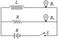
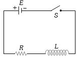
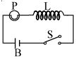
The resistance $R$ is the same as that of the coil that makes $L$. Which of the following statements gives the correct description of the happenings when the switch $S$ is closed?
A
The bulb $B_2$ lights up earlier than $B_1$ and finally both the bulbs shine equally bright.
B
$B_1$ lights up earlier and finally both the bulbs acquire equal brightness.
C
$B_2$ lights up earlier and finally $B_1$ shines brighter than $B_2$.
D
$B_1$ and $B_2$ light up together with equal brightness all the time.
Solution
(A) When the switch $S$ is closed, the current in the branch containing the inductor $L$ grows slowly due to the back $EMF$ induced by the inductor, which opposes the change in current $(e = -L \frac{di}{dt})$.
In the branch containing the resistor $R$, the current reaches its steady state value almost instantaneously.
Therefore, the bulb $B_2$ (in the resistor branch) lights up earlier than $B_1$ (in the inductor branch).
However, the problem states that the resistance of the coil $L$ is equal to the resistance $R$.
In the steady state, the inductor acts as a simple wire with resistance. Since the total resistance of both branches is the same (assuming the bulbs have identical resistance), the steady-state current in both branches will be equal.
Thus, both bulbs will eventually shine with equal brightness.
Wait, re-evaluating the standard problem: If the coil $L$ has internal resistance $r_L$ and we are given $r_L = R$, then the total resistance of the top branch is $R_{total} = r_L + R_{bulb1}$ and the bottom branch is $R_{total} = R + R_{bulb2}$. If $R_{bulb1} = R_{bulb2}$, then the final brightness is equal.
Looking at the provided options, option $(A)$ is the standard physical outcome for this circuit configuration.
0 likes
View Solution16
EasyMCQ
The time constant of an $LR$ circuit represents the time in which the current in the circuit
A
Reaches a value equal to about $37\%$ of its final value
B
Reaches a value equal to about $63\%$ of its final value
C
Attains a constant value
D
Attains $50\%$ of the constant value
Solution
(B) In an $LR$ circuit,the current $I$ at time $t$ is given by the equation $I(t) = I_0(1 - e^{-t/\tau})$,where $I_0$ is the maximum steady-state current and $\tau = L/R$ is the time constant.
When $t = \tau$,the current becomes $I(\tau) = I_0(1 - e^{-1})$.
Since $e^{-1} \approx 0.368$,we have $I(\tau) = I_0(1 - 0.368) = I_0(0.632)$.
This means the current reaches approximately $63\%$ of its final maximum value.
When $t = \tau$,the current becomes $I(\tau) = I_0(1 - e^{-1})$.
Since $e^{-1} \approx 0.368$,we have $I(\tau) = I_0(1 - 0.368) = I_0(0.632)$.
This means the current reaches approximately $63\%$ of its final maximum value.
0 likes
View Solution17
MediumMCQ
$A$ coil of inductance $300\, mH$ and resistance $2\, \Omega$ is connected to a source of voltage $2\, V$. The current reaches half of its steady state value in $t$ seconds. Find the value of $t$. (in $, s$)
A
$0.15$
B
$0.3$
C
$0.05$
D
$0.1$
Solution
(D) The current in an $LR$ circuit is given by $i = i_0(1 - e^{-Rt/L})$,where $i_0 = V/R$ is the steady state current.
We are given that the current reaches half of its steady state value,so $i = i_0/2$.
Substituting this into the equation: $i_0/2 = i_0(1 - e^{-Rt/L})$.
This simplifies to $1/2 = 1 - e^{-Rt/L}$,which means $e^{-Rt/L} = 1/2$.
Taking the natural logarithm on both sides: $-Rt/L = \ln(1/2) = -\ln(2)$.
Thus,$t = (L/R) \ln(2)$.
Given $L = 300\, mH = 0.3\, H$ and $R = 2\, \Omega$,we have $t = (0.3 / 2) \times 0.693$.
$t = 0.15 \times 0.693 = 0.10395\, s \approx 0.1\, s$.
0 likes
View Solution18
DifficultMCQ
An $e.m.f.$ of $15 \ V$ is applied in a circuit containing $5 \ H$ inductance and $10 \ \Omega$ resistance. The ratio of the currents at time $t = \infty$ and at $t = 1 \ s$ is:
A
$\frac{e^{1/2}}{e^{1/2} - 1}$
B
$\frac{e^2}{e^2 - 1}$
C
$1 - e^{-1}$
D
$e^{-1}$
Solution
(B) The current in an $R-L$ circuit at any time $t$ is given by $i(t) = i_0(1 - e^{-Rt/L})$,where $i_0 = E/R$ is the steady-state current.
Given: $E = 15 \ V$,$L = 5 \ H$,$R = 10 \ \Omega$.
Steady-state current $(t = \infty)$: $i_{\infty} = E/R = 15/10 = 1.5 \ A$.
At $t = 1 \ s$: $i_1 = i_0(1 - e^{-R(1)/L}) = 1.5(1 - e^{-10/5}) = 1.5(1 - e^{-2})$.
The ratio of currents is $\frac{i_{\infty}}{i_1} = \frac{1.5}{1.5(1 - e^{-2})} = \frac{1}{1 - e^{-2}} = \frac{1}{1 - 1/e^2} = \frac{e^2}{e^2 - 1}$.
0 likes
View Solution19
DifficultMCQ
An inductor of $2 \, H$ and a resistance of $10 \, \Omega$ are connected in series with a battery of $5 \, V$. The initial rate of change of current is ...... $A/s$.
A
$0.5$
B
$2$
C
$2.5$
D
$0.25$
Solution
(C) The current in an $LR$ series circuit is given by $i = i_0(1 - e^{-Rt/L})$,where $i_0 = E/R$.
Differentiating with respect to time $t$,we get the rate of change of current:
$\frac{di}{dt} = \frac{d}{dt} [i_0(1 - e^{-Rt/L})] = i_0 \cdot (\frac{R}{L}) e^{-Rt/L} = (\frac{E}{R}) \cdot (\frac{R}{L}) e^{-Rt/L} = \frac{E}{L} e^{-Rt/L}$.
At the initial moment,$t = 0$,the exponential term $e^0 = 1$.
Therefore,the initial rate of change of current is $\frac{di}{dt} = \frac{E}{L}$.
Given $E = 5 \, V$ and $L = 2 \, H$:
$\frac{di}{dt} = \frac{5}{2} = 2.5 \, A/s$.
0 likes
View Solution20
MediumMCQ
$A$ coil of inductance $8.4 \, mH$ and resistance $6 \, \Omega$ is connected to a $12 \, V$ battery. The current in the coil is $1.0 \, A$ at approximately the time
A
$500 \, s$
B
$20 \, s$
C
$35 \, ms$
D
$1 \, ms$
Solution
(D) The maximum current in the circuit is given by $i_0 = \frac{V}{R} = \frac{12 \, V}{6 \, \Omega} = 2 \, A$.
The current in an $LR$ circuit at time $t$ is given by $i(t) = i_0(1 - e^{-Rt/L})$.
We want to find the time $t$ when $i(t) = 1.0 \, A$. Substituting the values:
$1.0 = 2(1 - e^{-6t / (8.4 \times 10^{-3})})$
$0.5 = 1 - e^{-6t / (8.4 \times 10^{-3})}$
$e^{-6t / (8.4 \times 10^{-3})} = 0.5$
Taking the natural logarithm on both sides:
$-\frac{6t}{8.4 \times 10^{-3}} = \ln(0.5) \approx -0.693$
$t = 0.693 \times \frac{8.4 \times 10^{-3}}{6} = 0.693 \times 1.4 \times 10^{-3} \approx 0.97 \times 10^{-3} \, s \approx 1 \, ms$.
0 likes
View Solution21
DifficultMCQ
$A$ $50 \, V$ potential difference is suddenly applied to a coil with $L = 5 \times 10^{-3} \, H$ and $R = 180 \, \Omega$. The rate of increase of current after $0.001 \, s$ is ....... $A/s$.
A
$27.3$
B
$27.8$
C
$2.73$
D
None of the above
Solution
(D) The current in an $LR$ circuit at time $t$ is given by $i = i_0(1 - e^{-Rt/L})$, where $i_0 = V/R$.
The rate of increase of current is $\frac{di}{dt} = \frac{d}{dt} [i_0(1 - e^{-Rt/L})] = i_0 \cdot \frac{R}{L} e^{-Rt/L} = \frac{V}{R} \cdot \frac{R}{L} e^{-Rt/L} = \frac{V}{L} e^{-Rt/L}$.
Given $V = 50 \, V$, $L = 5 \times 10^{-3} \, H$, $R = 180 \, \Omega$, and $t = 0.001 \, s$.
Calculate the exponent: $\frac{Rt}{L} = \frac{180 \times 0.001}{5 \times 10^{-3}} = \frac{0.18}{0.005} = 36$.
Now, $\frac{di}{dt} = \frac{50}{5 \times 10^{-3}} e^{-36} = 10^4 \times e^{-36} \, A/s$.
Since $e^{-36}$ is an extremely small value, the result is approximately $10^4 \times 1.7 \times 10^{-16} \approx 1.7 \times 10^{-12} \, A/s$.
None of the given options match this value.
0 likes
View Solution22
MediumMCQ
When a battery is connected across a series combination of self inductance $L$ and resistance $R$,the variation in the current $i$ with time $t$ is best represented by
A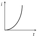
B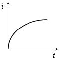
C
D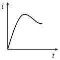
Solution
(B) When a battery of electromotive force $E$ is connected in series with an inductor $L$ and a resistor $R$,the circuit is known as an $RL$ circuit.
According to Kirchhoff's voltage law,the equation for the circuit is $E - L \frac{di}{dt} = iR$.
Rearranging the terms,we get $\frac{di}{dt} = \frac{E - iR}{L}$.
Solving this differential equation with the initial condition that at $t = 0$,$i = 0$,we get the expression for current as a function of time:
$i(t) = \frac{E}{R} (1 - e^{-\frac{R}{L}t})$.
Here,$i_0 = \frac{E}{R}$ is the maximum steady-state current.
The function $i(t) = i_0 (1 - e^{-\frac{R}{L}t})$ represents an exponential growth curve that starts from the origin $(0,0)$ and asymptotically approaches the value $i_0$ as $t$ approaches infinity.
Among the given options,the graph in option $B$ correctly depicts this exponential growth behavior.
0 likes
View Solution23
MediumMCQ
$A$ resistor of $20 \, \Omega$ and an inductor of $5 \, H$ are connected in series with a $5 \, V$ battery. What is the rate of change of current at $t = 0.25 \, s$?
A
$e$
B
$e^{-2}$
C
$e^{-1}$
D
None of these
Solution
(C) The current in an $RL$ circuit is given by $i(t) = \frac{E}{R}(1 - e^{-Rt/L})$.
The rate of change of current is $\frac{di}{dt} = \frac{d}{dt} [\frac{E}{R}(1 - e^{-Rt/L})] = \frac{E}{R} \cdot (\frac{R}{L}) e^{-Rt/L} = \frac{E}{L} e^{-Rt/L}$.
Given: $E = 5 \, V$, $R = 20 \, \Omega$, $L = 5 \, H$, and $t = 0.25 \, s$.
Calculate the exponent: $\frac{Rt}{L} = \frac{20 \times 0.25}{5} = \frac{5}{5} = 1$.
Substitute the values: $\frac{di}{dt} = \frac{5}{5} e^{-1} = 1 \cdot e^{-1} = e^{-1} \, A/s$.
0 likes
View Solution24
MediumMCQ
When the switch $S$ is closed at time $t = 0$,what will be the nature of the graphs for the induced $emf$ $e$ across the inductor $L$ and the current $i$ in the circuit?
A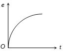
B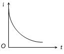
C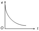
D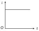
Solution
(B) In an $R-L$ circuit,when the switch $S$ is closed at $t = 0$,the current $i$ starts from zero and grows exponentially according to the equation $i(t) = \frac{E}{R}(1 - e^{-Rt/L})$. Thus,the graph of $i$ vs $t$ is an increasing curve.
The induced $emf$ across the inductor is given by $e = L \frac{di}{dt}$. Differentiating the current equation,we get $e(t) = E e^{-Rt/L}$. At $t = 0$,$e = E$ (maximum),and as $t$ increases,$e$ decays exponentially to zero. Thus,the graph of $e$ vs $t$ is a decreasing curve.
The induced $emf$ across the inductor is given by $e = L \frac{di}{dt}$. Differentiating the current equation,we get $e(t) = E e^{-Rt/L}$. At $t = 0$,$e = E$ (maximum),and as $t$ increases,$e$ decays exponentially to zero. Thus,the graph of $e$ vs $t$ is a decreasing curve.
0 likes
View Solution25
DifficultMCQ
In an $L-R$ circuit,the current reaches $\frac{3}{4}$ of its maximum value in $4 \ s$. What is the time constant of the $L-R$ circuit?
A
$\frac{1}{\ln 2} \ s$
B
$\frac{2}{\ln 2} \ s$
C
$\frac{3}{\ln 2} \ s$
D
$\frac{4}{\ln 2} \ s$
Solution
(B) The growth of current in an $L-R$ circuit is given by $i = i_0(1 - e^{-t/\tau})$,where $\tau = \frac{L}{R}$ is the time constant.
Given that at $t = 4 \ s$,$i = \frac{3}{4}i_0$.
Substituting these values: $\frac{3}{4}i_0 = i_0(1 - e^{-4/\tau})$.
$\frac{3}{4} = 1 - e^{-4/\tau} \implies e^{-4/\tau} = 1 - \frac{3}{4} = \frac{1}{4}$.
Taking the natural logarithm on both sides: $-\frac{4}{\tau} = \ln(\frac{1}{4}) = -\ln(4)$.
$\frac{4}{\tau} = \ln(2^2) = 2 \ln 2$.
$\tau = \frac{4}{2 \ln 2} = \frac{2}{\ln 2} \ s$.
0 likes
View Solution26
DifficultMCQ
In series with a $20 \ \Omega$ resistor,a $5 \ H$ inductor is placed. To this combination,an $e.m.f.$ of $5 \ V$ is applied. What will be the rate of increase of current at $t = 0.25 \ s$?
A
$e$
B
$e^{-2}$
C
$e^{-1}$
D
None of these
Solution
(C) The current $i$ in an $LR$ circuit is given by $i = i_0(1 - e^{-Rt/L})$,where $i_0 = E/R$.
Taking the derivative with respect to time $t$,we get the rate of increase of current:
$\frac{di}{dt} = \frac{d}{dt} [\frac{E}{R}(1 - e^{-Rt/L})] = \frac{E}{R} \cdot (\frac{R}{L}) e^{-Rt/L} = \frac{E}{L} e^{-Rt/L}$.
Given values: $E = 5 \ V$,$R = 20 \ \Omega$,$L = 5 \ H$,and $t = 0.25 \ s$.
Calculate the exponent: $\frac{Rt}{L} = \frac{20 \times 0.25}{5} = \frac{5}{5} = 1$.
Substitute the values into the expression for $\frac{di}{dt}$:
$\frac{di}{dt} = \frac{5}{5} e^{-1} = 1 \cdot e^{-1} = e^{-1} \ A/s$.
0 likes
View Solution27
MediumMCQ
For an $L-R$ circuit,the time constant is equal to
A
twice the ratio of the energy stored in the magnetic field to the rate of dissipation of energy in the resistance
B
the ratio of the energy stored in the magnetic field to the rate of dissipation of energy in the resistance
C
half the ratio of the energy stored in the magnetic field to the rate of dissipation of energy in the resistance
D
the square of the ratio of the energy stored in the magnetic field to the rate of dissipation of energy in the resistance
Solution
(A) In an $L-R$ circuit,the energy stored in the magnetic field of the inductor is given by $U = \frac{1}{2} L I^2$.
The rate of dissipation of energy in the resistance is given by $P = I^2 R$.
The ratio of the energy stored to the rate of dissipation is $\frac{U}{P} = \frac{\frac{1}{2} L I^2}{I^2 R} = \frac{1}{2} \frac{L}{R}$.
Since the time constant $\tau$ is defined as $\tau = \frac{L}{R}$,we have $\frac{U}{P} = \frac{1}{2} \tau$.
Therefore,the time constant $\tau = 2 \times \left( \frac{U}{P} \right)$,which is twice the ratio of the energy stored in the magnetic field to the rate of dissipation of energy in the resistance.
0 likes
View Solution28
MediumMCQ
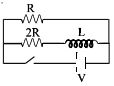
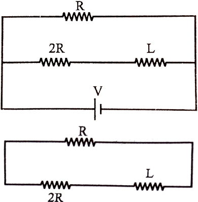
The ratio of the time constant in charging and discharging in the circuit shown in the figure is
A
$1 : 1$
B
$3 : 2$
C
$2 : 3$
D
$1 : 3$
Solution
(B) When the switch is closed (charging),the inductor $L$ is in series with the resistor $2R$. The resistor $R$ is in parallel with the series combination of $2R$ and $L$. The time constant for the charging circuit is determined by the equivalent resistance $R_{eq}$ seen by the inductor. When the battery is shorted (or considered ideal),the equivalent resistance is $R_{eq} = 2R + R = 3R$. Thus,the charging time constant is $\tau_{1} = \frac{L}{3R}$.
When the switch is opened (discharging),the inductor $L$ forms a closed loop with the resistors $2R$ and $R$ in series. The total resistance in this loop is $R_{eq} = 2R + R = 3R$. Thus,the discharging time constant is $\tau_{2} = \frac{L}{3R}$.
Wait,re-evaluating the circuit: When the switch is closed,the inductor is in series with $2R$. The resistor $R$ is in parallel with the branch containing $2R$ and $L$. The effective resistance seen by the inductor is $R_{eq} = 2R + 0 = 2R$ (since the battery is ideal,the parallel branch $R$ does not affect the time constant). So $\tau_{1} = \frac{L}{2R}$.
When the switch is opened,the inductor discharges through the series combination of $2R$ and $R$. So $R_{eq} = 2R + R = 3R$. Thus,$\tau_{2} = \frac{L}{3R}$.
The ratio $\frac{\tau_{1}}{\tau_{2}} = \frac{L/2R}{L/3R} = \frac{3}{2}$.
0 likes
View Solution29
AdvancedMCQ
$A$ coil of inductance $5\,H$ is joined to a cell of $emf$ $6\,V$ through a resistance $10\,\Omega$ at time $t = 0$. The $emf$ across the coil at time $t = \ln \sqrt{2}\,s$ is:....$V$
A
$3$
B
$1.5$
C
$0.75$
D
$4.5$
Solution
(A) Given: Inductance $L = 5\,H$,Resistance $R = 10\,\Omega$,$emf$ $V = 6\,V$.
The current in an $RL$ circuit at time $t$ is given by $i(t) = i_0(1 - e^{-Rt/L})$,where $i_0 = V/R = 6/10 = 0.6\,A$.
The time constant $\tau = L/R = 5/10 = 0.5\,s$. Thus,$i(t) = 0.6(1 - e^{-t/0.5}) = 0.6(1 - e^{-2t})$.
The $emf$ across the coil is given by $\varepsilon_L = L \frac{di}{dt}$.
Calculating $\frac{di}{dt}$: $\frac{di}{dt} = 0.6 \times (-2) \times (-e^{-2t}) = 1.2 e^{-2t}$.
Therefore,$\varepsilon_L = 5 \times 1.2 e^{-2t} = 6 e^{-2t}$.
At $t = \ln \sqrt{2} = \frac{1}{2} \ln 2$,we have $e^{-2t} = e^{-2(\frac{1}{2} \ln 2)} = e^{-\ln 2} = \frac{1}{2}$.
Substituting this value: $\varepsilon_L = 6 \times \frac{1}{2} = 3\,V$.
0 likes
View Solution30
MediumMCQ
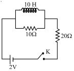
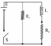
Two resistors of $10\, \Omega$ and $20\, \Omega$ and an ideal inductor of $10\, H$ are connected to a $2\, V$ battery as shown. The key $K$ is inserted at time $t = 0$. The initial $(t = 0)$ and final $(t \rightarrow \infty)$ currents through the battery are
A
$\frac{1}{15}\,A, \frac{1}{10}\,A$
B
$\frac{1}{10}\,A, \frac{1}{15}\,A$
C
$\frac{2}{15}\,A, \frac{1}{10}\,A$
D
$\frac{1}{15}\,A, \frac{2}{25}\,A$
Solution
(A) At $t = 0$,when the key is just closed,the inductor acts as an open circuit because it opposes any change in current. Therefore,the $10\, \Omega$ resistor and $20\, \Omega$ resistor are in series.
Total resistance $R_{eq} = 10\, \Omega + 20\, \Omega = 30\, \Omega$.
The initial current $I_0 = \frac{V}{R_{eq}} = \frac{2\, V}{30\, \Omega} = \frac{1}{15}\, A$.
As $t \rightarrow \infty$,the inductor acts as a short circuit (ideal inductor has zero resistance). The $10\, \Omega$ resistor is now in parallel with the short-circuited inductor,so all current flows through the inductor,bypassing the $10\, \Omega$ resistor.
Now,only the $20\, \Omega$ resistor is in the circuit.
The final current $I_{\infty} = \frac{V}{20\, \Omega} = \frac{2\, V}{20\, \Omega} = \frac{1}{10}\, A$.
0 likes
View Solution31
DifficultMCQ
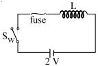
In the circuit shown,the cell is ideal. The coil has an inductance of $4H$ and zero resistance. $F$ is a fuse of zero resistance and will blow when the current through it reaches $5A$. The switch is closed at $t = 0$. The fuse will blow after how much time?
A
just after $t=0$
B
after $2s$
C
after $5s$
D
after $10s$
Solution
(D) Given: Electromotive force $E = 2V$,Inductance $L = 4H$,Fuse current $I = 5A$.
For an ideal inductor in a $DC$ circuit,the voltage across the inductor is given by $E = L \frac{di}{dt}$.
Rearranging the equation,we get $di = \frac{E}{L} dt$.
Integrating both sides from $t=0$ to $t$ and $i=0$ to $I$:
$\int_{0}^{I} di = \int_{0}^{t} \frac{E}{L} dt$
$I = \frac{E}{L} t$
Substituting the given values:
$5 = \frac{2}{4} t$
$5 = 0.5 t$
$t = \frac{5}{0.5} = 10s$
Thus,the fuse will blow after $10s$.
0 likes
View Solution32
MediumMCQ
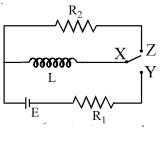
In the circuit shown,$X$ is joined to $Y$ for a long time,and then $X$ is joined to $Z$. The total heat produced in $R_2$ is:
A
$\frac{L E^2}{2 R_1^2}$
B
$\frac{L E^2}{2 R_2^2}$
C
$\frac{L E^2}{2 R_1 R_2}$
D
$\frac{L E^2 R_2}{2 R_1^2}$
Solution
(A) When $X$ is connected to $Y$ for a long time,the inductor $L$ acts as a short circuit (steady state). The current flowing through the inductor is $I_0 = \frac{E}{R_1}$.
The energy stored in the inductor is $U = \frac{1}{2} L I_0^2 = \frac{1}{2} L \left(\frac{E}{R_1}\right)^2 = \frac{L E^2}{2 R_1^2}$.
When $X$ is switched to $Z$,the inductor $L$ and resistor $R_2$ form a closed series circuit. The energy stored in the inductor is dissipated as heat in the resistor $R_2$ as the current decays to zero.
Since all the energy stored in the inductor is dissipated as heat in the circuit,the total heat produced in $R_2$ is equal to the initial energy stored in the inductor.
Therefore,the total heat $H = U = \frac{L E^2}{2 R_1^2}$.
0 likes
View Solution33
MediumMCQ
An induction coil stores $32 \ J$ of magnetic energy and dissipates energy as heat at the rate of $320 \ W$ when a current of $4 \ A$ is passed through it. Find the time constant of the circuit when the coil is joined across a battery.
A
$0.20$
B
$0.15$
C
$0.35$
D
$0.45$
Solution
(A) Let the inductance of the coil be $L$ and its resistance be $R$.
The magnetic energy stored in the inductor is given by $U = \frac{1}{2} L I^2$.
Given $U = 32 \ J$ and $I = 4 \ A$,we have:
$32 = \frac{1}{2} \times L \times (4)^2$
$32 = \frac{1}{2} \times L \times 16$
$32 = 8L \Rightarrow L = 4 \ H$.
The power dissipated as heat is given by $P = I^2 R$.
Given $P = 320 \ W$ and $I = 4 \ A$,we have:
$320 = (4)^2 \times R$
$320 = 16 \times R$
$R = \frac{320}{16} = 20 \ \Omega$.
The time constant $\tau$ of an $RL$ circuit is defined as $\tau = \frac{L}{R}$.
Substituting the values:
$\tau = \frac{4}{20} = 0.2 \ s$.
0 likes
View Solution34
AdvancedMCQ
In an $L-R$ decay circuit,the initial current at $t = 0$ is $I$. The total charge that has flown through the resistor until the energy in the inductor has reduced to one-fourth of its initial value is:
A
$LI/R$
B
$LI/2R$
C
$L/IR$
D
None
Solution
(B) The energy stored in an inductor is given by $U = \frac{1}{2} L i^2$.
Initially,$U_0 = \frac{1}{2} L I^2$.
When the energy reduces to one-fourth of its initial value,$U = \frac{1}{4} U_0 = \frac{1}{4} (\frac{1}{2} L I^2)$.
Thus,$\frac{1}{2} L i^2 = \frac{1}{4} (\frac{1}{2} L I^2)$,which implies $i^2 = \frac{1}{4} I^2$,so $i = \frac{I}{2}$.
In an $L-R$ decay circuit,the current at time $t$ is $i = I e^{-t/\tau}$,where $\tau = L/R$.
Setting $i = I/2$,we get $I/2 = I e^{-t/\tau}$,so $e^{-t/\tau} = 1/2$,which means $t/\tau = \ln 2$,or $t = \tau \ln 2$.
The total charge $q$ flown through the resistor is $q = \int_{0}^{t} i dt = \int_{0}^{\tau \ln 2} I e^{-t/\tau} dt$.
$q = I [-\tau e^{-t/\tau}]_{0}^{\tau \ln 2} = -I \tau (e^{-\ln 2} - e^0) = -I \tau (1/2 - 1) = -I \tau (-1/2) = \frac{I \tau}{2}$.
Substituting $\tau = L/R$,we get $q = \frac{IL}{2R}$.
0 likes
View Solution35
DifficultMCQ
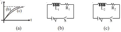
The current growth in two $L-R$ circuits $(b)$ and $(c)$ is shown in figure $(a)$. Let $L_1, L_2, R_1$ and $R_2$ be the corresponding values in the two circuits. Then:
A
$R_1 > R_2$
B
$R_1 = R_2$
C
$L_1 < L_2$
D
Both $(B)$ and $(C)$
Solution
(D) The expression for current growth in an $L-R$ circuit is given by $i = \frac{E}{R}(1 - e^{-t / \tau}) = I_0(1 - e^{-t / \tau})$,where $\tau = \frac{L}{R}$ is the time constant.
From the graph,both curves reach the same steady-state current $I_0 = \frac{E}{R}$. Since the battery voltage $E$ is the same for both circuits,we have $I_{0,1} = I_{0,2} \Rightarrow \frac{E}{R_1} = \frac{E}{R_2}$,which implies $R_1 = R_2$.
The time constant $\tau$ determines the rate of growth of current. $A$ larger time constant means the current takes longer to reach its steady state. From the graph,curve $(c)$ grows more slowly than curve $(b)$,so $\tau_c > \tau_b$.
Since $\tau = \frac{L}{R}$ and $R_1 = R_2$,we have $\frac{L_2}{R_2} > \frac{L_1}{R_1} \Rightarrow L_2 > L_1$,or $L_1 < L_2$.
Thus,both statements $(B)$ and $(C)$ are correct.
0 likes
View Solution36
MediumMCQ
An $LR$ circuit with a battery is connected at $t = 0$. Which of the following quantities is not zero just after the circuit is closed?
A
current in the circuit
B
magnetic field energy in the inductor
C
power delivered by the battery
D
$emf$ induced in the inductor
Solution
(D) At $t = 0$,the inductor opposes any change in current,acting as an open circuit.
$1$. Current in the circuit $(i)$: Since the inductor acts as an open circuit,$i = 0$.
$2$. Magnetic field energy $(U_B = \frac{1}{2} L i^2)$: Since $i = 0$,$U_B = 0$.
$3$. Power delivered by the battery $(P = V i)$: Since $i = 0$,$P = 0$.
$4$. Induced $emf$ in the inductor $(\varepsilon = L \frac{di}{dt})$: At $t = 0$,the rate of change of current $\frac{di}{dt}$ is maximum,making the induced $emf$ equal to the battery voltage $V$. Thus,it is non-zero.
0 likes
View Solution37
MediumMCQ
For $L-R$ circuit,the time constant is equal to
A
twice the ratio of the energy stored in the magnetic field to the rate of the dissipation of energy in the resistance.
B
the ratio of the energy stored in the magnetic field to the rate of dissipation of energy in the resistance.
C
half of the ratio of the energy stored in the magnetic field to the rate of dissipation of energy in the resistance.
D
square of the ratio of the energy stored in the magnetic field to the rate of dissipation energy in the resistance.
Solution
(A) In an $L-R$ circuit,the energy stored in the magnetic field of the inductor is given by $U = \frac{1}{2} L I^2$.
The rate of energy dissipation in the resistor is given by $P = I^2 R$.
The ratio of the energy stored to the rate of dissipation is $\frac{U}{P} = \frac{\frac{1}{2} L I^2}{I^2 R} = \frac{1}{2} \frac{L}{R}$.
Since the time constant $\tau$ is defined as $\tau = \frac{L}{R}$,we have $\frac{U}{P} = \frac{1}{2} \tau$.
Therefore,$\tau = 2 \times \frac{U}{P}$,which means the time constant is twice the ratio of the energy stored in the magnetic field to the rate of dissipation of energy in the resistance.
0 likes
View Solution38
MediumMCQ
In the figure,a lamp $P$ is in series with an iron-core inductor $L$. When the switch $S$ is closed,the brightness of the lamp rises relatively slowly to its full brightness compared to the case without the inductor. This is due to:
A
the low resistance of $P$
B
the induced $emf$ in $L$
C
the low resistance of $L$
D
the high voltage of the battery $B$
Solution
(B) When the switch $S$ is closed,the current in the circuit starts to increase from zero.
As the current changes,a changing magnetic flux is linked with the inductor $L$.
According to Faraday's law of electromagnetic induction,this changing flux induces an $emf$ in the inductor.
According to Lenz's law,this induced $emf$ opposes the growth of the current in the circuit.
Therefore,the current takes some time to reach its steady-state value,causing the lamp $P$ to reach its full brightness slowly.
0 likes
View Solution39
DifficultMCQ
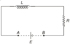
An inductor $(L = 100 \ mH)$,a resistor $(R = 100 \ \Omega)$ and a battery $(E = 100 \ V)$ are initially connected in series as shown in the figure. After a long time,the battery is disconnected by short-circuiting the points $A$ and $B$. The current in the circuit $1 \ ms$ after the short circuit is
A
$\frac{1}{e} \ A$
B
$e \ A$
C
$0.1 \ A$
D
$1 \ A$
Solution
(A) Initially,when steady state is achieved,the current in the circuit is $i_0 = \frac{E}{R} = \frac{100 \ V}{100 \ \Omega} = 1 \ A$.
When the battery is disconnected and points $A$ and $B$ are short-circuited,the circuit becomes an $LR$ decay circuit.
The equation for the decay of current is given by $i(t) = i_0 e^{-\frac{R}{L}t}$.
Given $R = 100 \ \Omega$,$L = 100 \ mH = 0.1 \ H$,and $t = 1 \ ms = 10^{-3} \ s$.
The time constant of the circuit is $\tau = \frac{L}{R} = \frac{0.1 \ H}{100 \ \Omega} = 10^{-3} \ s$.
Substituting the values into the decay equation:
$i(t) = 1 \times e^{-\frac{10^{-3}}{10^{-3}}} = 1 \times e^{-1} = \frac{1}{e} \ A$.
0 likes
View Solution40
MediumMCQ
An ideal coil of $10 \ H$ is connected in series with a resistance of $5 \ \Omega$ and a battery of $5 \ V$. $2 \ s$ after the connection is made,the current flowing in the circuit in amperes is:
A
$e^{-1}$
B
$(1 - e^{-1})$
C
$(1 - e)$
D
$e$
Solution
(B) The growth of current in an $LR$ circuit is given by the formula: $I = I_0(1 - e^{-\frac{R}{L}t})$.
Here,$I_0 = \frac{E}{R}$ is the maximum steady-state current.
Given: $L = 10 \ H$,$R = 5 \ \Omega$,$E = 5 \ V$,and $t = 2 \ s$.
First,calculate the maximum current: $I_0 = \frac{5 \ V}{5 \ \Omega} = 1 \ A$.
Now,substitute the values into the growth equation:
$I = 1 \times (1 - e^{-\frac{5}{10} \times 2})$
$I = 1 - e^{-1} \ A$.
0 likes
View Solution41
DifficultMCQ
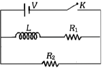
An inductor of inductance $L = 400 \ mH$ and resistors of resistance $R_1 = 2 \ \Omega$ and $R_2 = 2 \ \Omega$ are connected to a battery of emf $E = 12 \ V$ as shown in the figure. The internal resistance of the battery is negligible. The switch $S$ is closed at $t = 0$. The potential drop across $L$ as a function of time is:
A
$6e^{-5t} \ V$
B
$\frac{12}{t}e^{-3t} \ V$
C
$6(1 - e^{-t/0.2}) \ V$
D
$12e^{-5t} \ V$
Solution
(D) When the switch $S$ is closed at $t = 0$,the branch containing $R_1$ is in parallel with the branch containing $L$ and $R_2$. The potential difference across the $L-R_2$ branch is equal to the emf of the battery,$E = 12 \ V$.
The current $i$ in the $L-R_2$ branch grows according to the equation: $i = \frac{E}{R_2}(1 - e^{-R_2 t / L})$.
The potential drop across the inductor $L$ is given by $V_L = L \frac{di}{dt}$.
Differentiating the current expression with respect to time $t$:
$\frac{di}{dt} = \frac{E}{R_2} \cdot \frac{R_2}{L} e^{-R_2 t / L} = \frac{E}{L} e^{-R_2 t / L}$.
Substituting this into the expression for $V_L$:
$V_L = L \left( \frac{E}{L} e^{-R_2 t / L} \right) = E e^{-R_2 t / L}$.
Given $E = 12 \ V$,$R_2 = 2 \ \Omega$,and $L = 400 \ mH = 0.4 \ H$,the time constant $\tau = \frac{L}{R_2} = \frac{0.4}{2} = 0.2 \ s$.
Thus,$V_L = 12 e^{-t / 0.2} = 12 e^{-5t} \ V$.
0 likes
View Solution42
DifficultMCQ
In the circuit shown below,the key $K$ is closed at $t = 0$. The current through the battery is
A
$\frac{V}{R_2}$ at $t = 0$ and $\frac{V(R_1 + R_2)}{R_1 R_2}$ at $t = \infty$
B
$\frac{V R_1 R_2}{\sqrt{R_1^2 + R_2^2}}$ at $t = 0$ and $\frac{V}{R_2}$ at $t = \infty$
C
$\frac{V(R_1 + R_2)}{R_1 R_2}$ at $t = 0$ and $\frac{V}{R_2}$ at $t = \infty$
D
$\frac{V}{R_2}$ at $t = 0$ and $\frac{V R_1 R_2}{\sqrt{R_1^2 + R_2^2}}$ at $t = \infty$
Solution
(A) At $t = 0$,the inductor $L$ acts as an open circuit because it opposes any change in current. Therefore,no current flows through the branch containing $L$ and $R_1$.
Thus,the current through the battery is $I = \frac{V}{R_2}$.
At $t = \infty$,the inductor $L$ acts as a short circuit (ideal inductor with zero resistance). The resistors $R_1$ and $R_2$ are now in parallel.
The effective resistance of the circuit is $R_{eff} = \frac{R_1 R_2}{R_1 + R_2}$.
Therefore,the current through the battery is $I = \frac{V}{R_{eff}} = \frac{V(R_1 + R_2)}{R_1 R_2}$.
0 likes
View Solution43
MediumMCQ
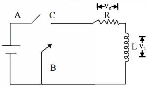
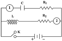
In the circuit shown here, the point '$C$' is kept connected to point '$A$' till the current flowing through the circuit becomes constant. Afterward, suddenly, point '$C$' is disconnected from point '$A$' and connected to point '$B$' at time $t = 0$. The ratio of the voltage across the resistance $(V_R)$ and the inductor $(V_L)$ at $t = L/R$ will be equal to:
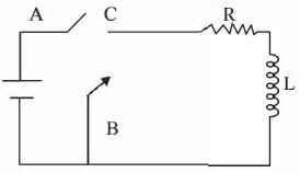
A
$1$
B
$-1$
C
$\frac{1 - e}{e}$
D
$\frac{e}{1 - e}$
Solution
(B) $1$. When point '$C$' is connected to '$A$', the current in the circuit becomes constant, $I_0 = E/R$. The inductor acts as a short circuit.
$2$. When '$C$' is connected to '$B$' at $t = 0$, the battery is removed, and the circuit becomes a decaying $LR$ circuit.
$3$. The current in the circuit at time $t$ is given by $I(t) = I_0 e^{-Rt/L}$.
$4$. At $t = L/R$, the current is $I = I_0 e^{-R(L/R)/L} = I_0 e^{-1} = I_0/e$.
$5$. The voltage across the resistance is $V_R = I R = (I_0/e) R = (E/R \cdot 1/e) R = E/e$.
$6$. Applying Kirchhoff's voltage law in the closed loop (without battery): $V_R + V_L = 0$, which implies $V_L = -V_R$.
$7$. Therefore, the ratio of the voltage across the resistance $(V_R)$ to the voltage across the inductor $(V_L)$ is $V_R / V_L = V_R / (-V_R) = -1$.
0 likes
View Solution44
DifficultMCQ
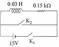
An inductor $(L = 0.03 \; H)$ and a resistor $(R = 0.15 \; k\Omega)$ are connected in series to a battery of $15 \; V$ $EMF$ in the circuit shown below. The key $K_1$ has been kept closed for a long time. Then at $t = 0$,$K_1$ is opened and key $K_2$ is closed simultaneously. At $t = 1 \; ms$,the current in the circuit will be ........... $mA$. $(e^5 \cong 150)$
A
$67$
B
$6.7$
C
$0.67$
D
$100$
Solution
(C) $1$. When key $K_1$ is closed for a long time,the inductor acts as a short circuit. The steady-state current $i_0$ in the circuit is given by $i_0 = \frac{V}{R} = \frac{15}{0.15 \times 10^3} = 0.1 \; A$.
$2$. At $t = 0$,$K_1$ is opened and $K_2$ is closed. The battery is removed from the circuit,and the inductor discharges through the resistor. This is a decaying $LR$ circuit.
$3$. The current at time $t$ is given by $i = i_0 e^{-\frac{Rt}{L}}$.
$4$. Substituting the values: $i = 0.1 \times e^{-\frac{0.15 \times 10^3 \times 10^{-3}}{0.03}} = 0.1 \times e^{-\frac{0.15}{0.03}} = 0.1 \times e^{-5}$.
$5$. Given $e^5 \cong 150$,then $e^{-5} = \frac{1}{150}$.
$6$. Therefore,$i = 0.1 \times \frac{1}{150} = \frac{0.1}{150} \; A = \frac{0.1}{150} \times 1000 \; mA = \frac{100}{150} \; mA = \frac{2}{3} \; mA \approx 0.67 \; mA$.
0 likes
View Solution45
MediumMCQ
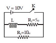
In the circuit shown below,the key $K$ is closed at $t = 0$. The current through the battery is
A
$5 \ A$ at $t = 0$ and $7 \ A$ at $t = \infty$
B
$3 \ A$ at $t = 0$ and $1 \ A$ at $t = \infty$
C
$1 \ A$ at $t = 0$ and $3 \ A$ at $t = \infty$
D
$2 \ A$ at $t = 0$ and $6 \ A$ at $t = \infty$
Solution
(C) At $t = 0$,the inductor $L$ acts as an open circuit. The current flows only through resistor $R_2 = 10 \ \Omega$. Therefore,the current $I_0 = V / R_2 = 10 \ V / 10 \ \Omega = 1 \ A$.
At $t = \infty$,the inductor $L$ acts as a short circuit. The circuit consists of two resistors $R_1 = 5 \ \Omega$ and $R_2 = 10 \ \Omega$ in parallel. The equivalent resistance $R_{eq} = (R_1 \times R_2) / (R_1 + R_2) = (5 \times 10) / (5 + 10) = 50 / 15 = 10 / 3 \ \Omega$.
The current $I_{\infty} = V / R_{eq} = 10 / (10 / 3) = 3 \ A$.
0 likes
View Solution46
DifficultMCQ
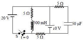
Switch $S$ is closed at $t = 0$ in the circuit shown. The change in magnetic flux in the inductor $(L = 500 \, mH)$ from $t = 0$ to an instant when it reaches steady state is ...... $Wb$.
A
$2$
B
$1.5$
C
$0$
D
None
Solution
(A) At $t = 0$,the switch $S$ is open. The inductor acts as an open circuit,but the current flows through the $20 \, V$ battery,the $5 \, \Omega$ resistor,the $5 \, \Omega$ resistor,and the $10 \, V$ battery. The current $I_0$ through the inductor branch is $0 \, A$ because the switch is open.
At steady state $(t \to \infty)$,the inductor acts as a short circuit (zero resistance). The capacitor acts as an open circuit. The circuit simplifies to a loop with the $20 \, V$ battery,the $5 \, \Omega$ resistor,and the inductor branch (with $5 \, \Omega$ resistance). The $10 \, V$ battery branch is in parallel with the inductor branch. The current $I$ through the inductor is determined by the $20 \, V$ source and the $5 \, \Omega$ resistor in series with the inductor branch: $I = \frac{20 \, V}{5 \, \Omega} = 4 \, A$.
The change in flux is $\Delta \phi = L \Delta I = L(I_{final} - I_{initial})$.
Given $L = 500 \, mH = 0.5 \, H$,$I_{initial} = 0 \, A$,and $I_{final} = 4 \, A$.
$\Delta \phi = 0.5 \times (4 - 0) = 2 \, Wb$.
0 likes
View Solution47
EasyMCQ
$A$ bulb of $100\, W$ is connected in parallel with an ideal inductance of $1\, H$. This arrangement is connected to a $90\, V$ battery through a switch. On pressing the switch,the
A
bulb does not glow
B
bulb glows
C
bulb glows after a short time and then continues to glow
D
bulb glows for a short time and then stops glowing
Solution
(A) When the switch is closed,the circuit is connected to a $90\, V$ $DC$ battery.
An ideal inductor has zero resistance,so it acts as a short circuit for $DC$ current.
Since the bulb and the inductor are connected in parallel,the entire current from the battery will flow through the path of least resistance,which is the ideal inductor.
Consequently,no current flows through the bulb,and it does not glow.
0 likes
View Solution48
MediumMCQ
In the circuit shown,an inductor $L$ and a capacitor $C$ are connected as shown. $A_1$ and $A_2$ are ammeters. When the key $K$ is pressed to complete the circuit,what will be the readings of $A_1$ and $A_2$ just after closing the key $K$?
A
zero in both $A_1$ and $A_2$
B
maximum in both $A_1$ and $A_2$
C
maximum in $A_1$ and zero in $A_2$
D
zero in $A_1$ and maximum in $A_2$
Solution
(C) At the instant the key $K$ is closed $(t=0)$:
$(i)$ $A$ capacitor acts as a short circuit (offers zero resistance) because it is initially uncharged,allowing maximum current to flow through the branch containing $A_1$.
$(ii)$ An inductor opposes any change in current. Since the current was zero before closing the key,the inductor acts as an open circuit (offers infinite resistance) at $t=0$,resulting in zero current through the branch containing $A_2$.
Therefore,the reading of $A_1$ is maximum and the reading of $A_2$ is zero.
0 likes
View Solution49
DifficultMCQ
$A$ coil of inductance $1\, H$ and resistance $10\, \Omega$ is connected to a battery of $emf$ $50\, V$ and negligible internal resistance at time $t = 0.$ The ratio of the rate at which magnetic energy is stored in the coil to the rate at which energy is supplied by the battery at $t = 0.1\, s$ is:
A
$0.72$
B
$0.18$
C
$0.36$
D
$0.12$
Solution
(C) The rate at which magnetic energy is stored in the coil is given by $P_m = \frac{d}{dt}(\frac{1}{2}Li^2) = Li \frac{di}{dt}$.
The rate at which energy is supplied by the battery is $P_b = Ei$.
The ratio of these rates is $\frac{P_m}{P_b} = \frac{Li \frac{di}{dt}}{Ei} = \frac{L}{E} \frac{di}{dt}$.
For an $RL$ circuit,the current at time $t$ is $i = \frac{E}{R}(1 - e^{-Rt/L})$.
The rate of change of current is $\frac{di}{dt} = \frac{E}{R} \cdot \frac{R}{L} e^{-Rt/L} = \frac{E}{L} e^{-Rt/L}$.
Substituting this into the ratio expression:
$\frac{P_m}{P_b} = \frac{L}{E} \left( \frac{E}{L} e^{-Rt/L} \right) = e^{-Rt/L}$.
Given $R = 10\, \Omega$,$L = 1\, H$,and $t = 0.1\, s$:
$\frac{P_m}{P_b} = e^{-(10 \times 0.1) / 1} = e^{-1} \approx \frac{1}{2.718} \approx 0.368 \approx 0.36$.
0 likes
View SolutionElectromagnetic Induction — R-L D.C. Circuit · Frequently Asked Questions
1Are these Electromagnetic Induction questions useful for JEE and NEET?
Yes. All questions in this section are mapped to JEE Main and NEET exam patterns. Previous year questions from JEE Main, NEET, GUJCET and state-level exams are included with full solutions.
2Can I switch to Hindi or Gujarati for these questions?
Yes. Use the language tabs in the hero section or the sidebar to view the same questions and solutions in English, Hindi or Gujarati.
3How do I generate a question paper from this subtopic?
Use the Vedclass Exam Paper Generator — select the chapter and subtopic, set difficulty, and generate Sets A, B, C, D automatically. First 3 chapters of every subject are free.
Vedclass Products
For Students
Vedclass Test Series
Mock tests in real JEE/NEET style with performance analysis. 5-day free trial.
Start Free TrialFor Teachers
Exam Paper Generator
Generate Set A/B/C/D papers from this chapter in 2 minutes. 3 chapters free.
Try FreeFor Institutes
Online Exam Module
Live online exams with unlimited students, 360° analytics & white-label branding.
See DemoFor Teachers & Institutes
Generate a Electromagnetic Induction Exam Paper in 2 Minutes
Select subtopic & difficulty — Sets A, B, C, D auto-generated with No Repeat logic.
First 3 chapters of every subject are free — no payment required.