
A English
Boolean Algebra and Logic Gates Questions in English
Class 12 Physics · Semiconductor Electronics · Boolean Algebra and Logic Gates
483+
Questions
English
Language
100%
With Solutions
Showing 50 of 483 questions in English
351
EasyMCQ
In the case of a $NAND$ gate,if $A$ and $B$ are the inputs and $Y$ is the output,then:
A
$Y=A \cdot B$
B
$Y=\overline{A-B}$
C
$Y=\overline{A+B}$
D
$Y=\overline{A \cdot B}$
Solution
(D) $NAND$ gate is a combination of an $AND$ gate followed by a $NOT$ gate.
First,the $AND$ operation is performed on inputs $A$ and $B$,which results in $A \cdot B$.
Then,the $NOT$ operation is applied to this result,which inverts the output.
Therefore,the output $Y$ of a $NAND$ gate is given by the Boolean expression $Y = \overline{A \cdot B}$.
First,the $AND$ operation is performed on inputs $A$ and $B$,which results in $A \cdot B$.
Then,the $NOT$ operation is applied to this result,which inverts the output.
Therefore,the output $Y$ of a $NAND$ gate is given by the Boolean expression $Y = \overline{A \cdot B}$.
0 likes
View Solution352
EasyMCQ
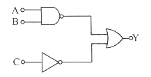
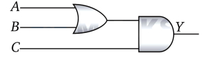
In the digital circuit,the inputs are as shown in the figure. The Boolean expression for output $Y$ is
A
$\overline{A+B}+\overline{C}$
B
$\overline{A \cdot B} \cdot \overline{C}$
C
$\overline{A \cdot B}+\overline{C}$
D
$\overline{A+B} \cdot \overline{C}$
Solution
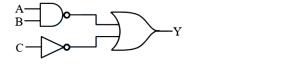
(C) The given circuit consists of a $NAND$ gate and a $NOT$ gate,whose outputs are fed into an $OR$ gate.
$1$. The inputs $A$ and $B$ are fed into a $NAND$ gate. The output of the $NAND$ gate is $\overline{A \cdot B}$.
$2$. The input $C$ is fed into a $NOT$ gate. The output of the $NOT$ gate is $\overline{C}$.
$3$. These two outputs are then fed into an $OR$ gate. The $OR$ operation of two inputs $X$ and $Z$ is $X+Z$.
$4$. Therefore,the final output $Y$ is the $OR$ sum of the two previous outputs: $Y = \overline{A \cdot B} + \overline{C}$.
0 likes
View Solution353
EasyMCQ
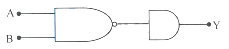
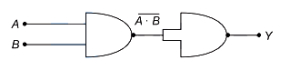
The logic gate combination circuit shown in the figure performs the logic function of
A
$AND$ gate
B
$NAND$ gate
C
$OR$ gate
D
The gate is not operational
Solution
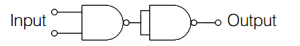
(D) The circuit consists of a $NAND$ gate followed by an $AND$ gate.
In the provided diagram,the output of the $NAND$ gate is connected to only one input terminal of the $AND$ gate.
An $AND$ gate is a multi-input logic gate that requires at least two input signals to perform its logical operation.
Since the $AND$ gate in this circuit is receiving only one input,it cannot function as a standard logic gate.
Therefore,the gate is not operational.
0 likes
View Solution354
EasyMCQ
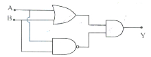
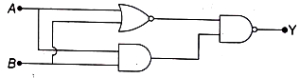
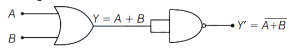
The following logic gate combination is equivalent to
A
$NAND$ gate
B
$OR$ gate
C
$XOR$ gate
D
$NOT$ gate
Solution
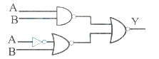
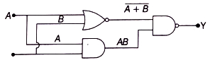
(C) The given circuit consists of an $OR$ gate and a $NAND$ gate whose outputs are fed into an $AND$ gate.
Let the inputs be $A$ and $B$.
The output of the $OR$ gate is $(A + B)$.
The output of the $NAND$ gate is $(\overline{A \cdot B})$.
These are the inputs to the final $AND$ gate.
Therefore,the final output $Y$ is given by:
$Y = (A + B) \cdot (\overline{A \cdot B})$
Using De Morgan's theorem,$\overline{A \cdot B} = \bar{A} + \bar{B}$.
$Y = (A + B) \cdot (\bar{A} + \bar{B})$
$Y = A \cdot \bar{A} + A \cdot \bar{B} + B \cdot \bar{A} + B \cdot \bar{B}$
Since $A \cdot \bar{A} = 0$ and $B \cdot \bar{B} = 0$,we have:
$Y = 0 + A \cdot \bar{B} + B \cdot \bar{A} + 0$
$Y = A \cdot \bar{B} + \bar{A} \cdot B$
This is the Boolean expression for an $XOR$ gate.
0 likes
View Solution355
EasyMCQ
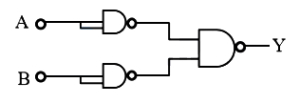
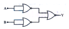
In the following digital logic circuit,the output $Y$ will be ' $1$ ' for inputs:
A
$A=0, B=0$
B
$A=0, B=1$
C
$A=1, B=0$
D
$A=1, B=1$
Solution
(D) The circuit consists of one $NAND$ gate,one $NOT$ gate,one $NOR$ gate,and one final $NOR$ gate.
Let the output of the top $NAND$ gate be $Y_1 = \overline{A \cdot B}$.
Let the output of the bottom branch ($NOT$ gate followed by $NOR$ gate) be $Y_2 = \overline{\overline{A} + B}$.
The final output $Y$ is the output of a $NOR$ gate with inputs $Y_1$ and $Y_2$,so $Y = \overline{Y_1 + Y_2} = \overline{(\overline{A \cdot B}) + (\overline{\overline{A} + B})}$.
Testing the options:
For $A=1, B=1$:
$Y_1 = \overline{1 \cdot 1} = 0$
$Y_2 = \overline{\overline{1} + 1} = \overline{0 + 1} = 0$
$Y = \overline{0 + 0} = 1$.
Thus,for $A=1, B=1$,the output $Y$ is $1$.
0 likes
View Solution356
EasyMCQ
If two inputs of a $NAND$ gate are shorted,the resulting gate is
A
an $OR$ gate
B
a $AND$ gate
C
an $NOT$ gate
D
a $NOR$ gate
Solution
(C) $NAND$ gate has two inputs,say $A$ and $B$,and its output is given by $Y = \overline{A \cdot B}$.
If the two inputs are shorted,then $A = B$. Let this common input be $A$.
Substituting this into the $NAND$ expression,we get $Y = \overline{A \cdot A}$.
Since $A \cdot A = A$ in Boolean algebra,the expression becomes $Y = \overline{A}$.
The expression $Y = \overline{A}$ represents the operation of a $NOT$ gate.
Therefore,when the inputs of a $NAND$ gate are shorted,it functions as a $NOT$ gate.
0 likes
View Solution357
EasyMCQ
The Boolean expression for the following combination is
A
$(\overline{A+B})\cdot(A+B)$
B
$(\overline{A \cdot B})+(A \cdot B)$
C
$(\overline{A} \cdot B)+(A \cdot \overline{B})$
D
$(\overline{A}+B)\cdot(A+\overline{B})$
Solution
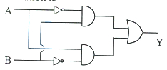
(C) The given circuit consists of two $NOT$ gates,two $AND$ gates,and one $OR$ gate.
$1$. The input $A$ passes through a $NOT$ gate to become $\overline{A}$,and input $B$ goes directly to the first $AND$ gate. The output of this $AND$ gate is $\overline{A} \cdot B$.
$2$. The input $B$ passes through a $NOT$ gate to become $\overline{B}$,and input $A$ goes directly to the second $AND$ gate. The output of this $AND$ gate is $A \cdot \overline{B}$.
$3$. These two outputs are then fed into an $OR$ gate. The final output $Y$ is the sum of these two expressions: $Y = (\overline{A} \cdot B) + (A \cdot \overline{B})$.
This is the Boolean expression for an $XOR$ gate.
0 likes
View Solution358
EasyMCQ
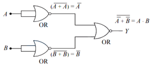
The output of the following combination is the same as that of:
A
$AND$ gate
B
$OR$ gate
C
$NAND$ gate
D
$NOR$ gate
Solution
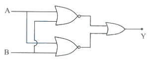
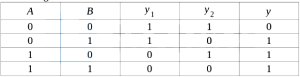
(D) The given circuit consists of two $NOR$ gates whose outputs are fed into an $OR$ gate. Let the inputs be $A$ and $B$. The output of the top $NOR$ gate is $C = \overline{A+B}$ and the output of the bottom $NOR$ gate is $D = \overline{A+B}$. These are fed into an $OR$ gate,so the final output is $Y = C + D = \overline{A+B} + \overline{A+B} = \overline{A+B}$.
The truth table for this combination is:
Comparing this with the truth table of standard logic gates,the output $Y$ is $1$ only when both $A$ and $B$ are $0$,which is the characteristic behavior of a $NOR$ gate.
The truth table for this combination is:
| $A$ | $B$ | $C = \overline{A+B}$ | $D = \overline{A+B}$ | $Y = C + D$ |
|---|---|---|---|---|
| $0$ | $0$ | $1$ | $1$ | $1$ |
| $0$ | $1$ | $0$ | $0$ | $0$ |
| $1$ | $0$ | $0$ | $0$ | $0$ |
| $1$ | $1$ | $0$ | $0$ | $0$ |
Comparing this with the truth table of standard logic gates,the output $Y$ is $1$ only when both $A$ and $B$ are $0$,which is the characteristic behavior of a $NOR$ gate.
0 likes
View Solution359
EasyMCQ
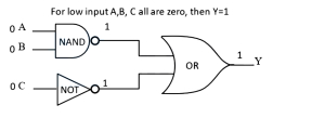
The output $Y$ when all the three inputs $A, B, C$ are first low and then high will be
A
$1, 0$
B
$1, 1$
C
$0, 0$
D
$0, 1$
Solution
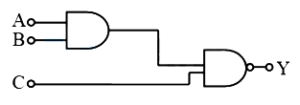
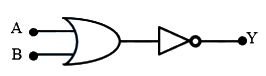
(A) The given circuit consists of a $NAND$ gate with inputs $A$ and $B$, a $NOT$ gate with input $C$, and an $OR$ gate that combines their outputs.
The Boolean expression for the output $Y$ is $Y = (\overline{A \cdot B}) + \overline{C}$.
Case $1$: When all inputs $A, B, C$ are low $(0, 0, 0)$:
$A = 0, B = 0 \implies A \cdot B = 0 \implies \overline{A \cdot B} = 1$.
$C = 0 \implies \overline{C} = 1$.
$Y = 1 + 1 = 1$.
Case $2$: When all inputs $A, B, C$ are high $(1, 1, 1)$:
$A = 1, B = 1 \implies A \cdot B = 1 \implies \overline{A \cdot B} = 0$.
$C = 1 \implies \overline{C} = 0$.
$Y = 0 + 0 = 0$.
Thus, the output sequence is $1, 0$.
0 likes
View Solution360
EasyMCQ
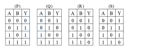
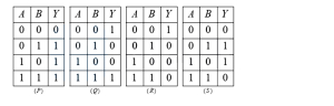
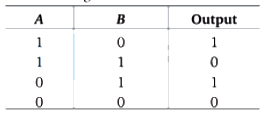
The output of a $NAND$ gate is shown in the truth-table ($A$ and $B$ are inputs, $Y$ is output). Identify the correct truth-table.
A
$Q$
B
$R$
C
$S$
D
$P$
Solution
(C) $NAND$ gate is a combination of an $AND$ gate followed by a $NOT$ gate.
The Boolean expression for a $NAND$ gate is $Y = \overline{A \cdot B}$.
Let us evaluate the output $Y$ for all possible input combinations of $A$ and $B$:
$1$. If $A = 0, B = 0$, then $A \cdot B = 0$, so $Y = \overline{0} = 1$.
$2$. If $A = 0, B = 1$, then $A \cdot B = 0$, so $Y = \overline{0} = 1$.
$3$. If $A = 1, B = 0$, then $A \cdot B = 0$, so $Y = \overline{0} = 1$.
$4$. If $A = 1, B = 1$, then $A \cdot B = 1$, so $Y = \overline{1} = 0$.
Comparing this with the given tables:
- Table $(P)$ represents an $OR$ gate.
- Table $(Q)$ represents an $XOR$ gate.
- Table $(R)$ represents an $AND$ gate.
- Table $(S)$ represents a $NAND$ gate.
Thus, the correct truth-table is $(S)$.
0 likes
View Solution361
EasyMCQ
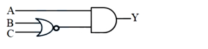
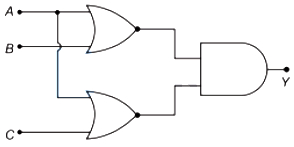
In the given logic circuit diagram,$A$,$B$,and $C$ are the inputs,and $Y$ is the output. The output $Y$ is ' $HIGH$ ' (i.e.,$Y=1$):
A
when $A=1, B=0, C=1$
B
for all the inputs ' $HIGH$ '
C
for all the inputs ' $LOW$ '
D
when $A=1, B=0, C=0$
Solution
(D) The logic circuit consists of a $NOR$ gate followed by an $AND$ gate.
The inputs to the $NOR$ gate are $B$ and $C$,so its output is $\overline{B+C}$.
This output is then fed into an $AND$ gate along with input $A$.
Therefore,the final output $Y$ is given by the Boolean expression: $Y = A \cdot \overline{(B+C)}$.
For the output $Y$ to be ' $HIGH$ ' $(Y=1)$,both $A$ must be $1$ and $\overline{(B+C)}$ must be $1$.
$\overline{(B+C)} = 1$ implies that $(B+C) = 0$,which means both $B=0$ and $C=0$.
Thus,$Y=1$ when $A=1, B=0$,and $C=0$.
0 likes
View Solution362
EasyMCQ
Which one of the following logic gates is called a Universal gate?
A
$NOR$
B
$NOT$
C
Ex-$OR$
D
$AND$
Solution
(A) Universal gate is a logic gate that can be used to implement any other logic gate or Boolean function without the need for any other type of gate.
Both $NAND$ and $NOR$ gates are classified as Universal gates.
Since $NOR$ is the only option provided that fits this definition,the correct answer is $NOR$.
Both $NAND$ and $NOR$ gates are classified as Universal gates.
Since $NOR$ is the only option provided that fits this definition,the correct answer is $NOR$.
0 likes
View Solution363
EasyMCQ
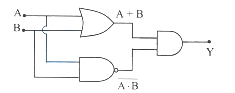
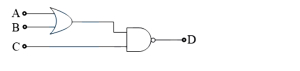
For the given combination of logic gates,the inputs $A, B$ and $C$ are as follows. If $A=B=C=0$ and $A=B=1, C=0$,then the logic states of output $D$ are respectively:
A
$0$,$0$
B
$0$,$1$
C
$1$,$0$
D
$1$,$1$
Solution
(D) The given circuit consists of an $OR$ gate followed by a $NAND$ gate.
The output of the $OR$ gate is $Y = A + B$.
This output $Y$ is one of the inputs to the $NAND$ gate,and the other input is $C$.
The final output $D$ of the $NAND$ gate is $D = \overline{Y \cdot C} = \overline{(A + B) \cdot C}$.
Case $1$: $A=0, B=0, C=0$
$Y = 0 + 0 = 0$
$D = \overline{0 \cdot 0} = \overline{0} = 1$
Case $2$: $A=1, B=1, C=0$
$Y = 1 + 1 = 1$
$D = \overline{1 \cdot 0} = \overline{0} = 1$
Thus,the logic states of output $D$ are $1, 1$.
0 likes
View Solution364
EasyMCQ
The output of an $OR$ gate is $1$:
A
if either input is $0$
B
only if both inputs are $0$
C
if either or both inputs are $1$
D
only if both inputs are $1$
Solution
(C) The $OR$ gate is a basic logic gate that performs logical addition.
For an $OR$ gate with inputs $A$ and $B$,the output $Y$ is given by the Boolean expression $Y = A + B$.
According to the truth table of an $OR$ gate,the output is $1$ if at least one of the inputs is $1$.
Specifically,if input $A$ is $1$ or input $B$ is $1$,or if both inputs $A$ and $B$ are $1$,the output $Y$ will be $1$.
0 likes
View Solution365
EasyMCQ
What will be the input of $A$ and $B$ for the Boolean expression $\overline{(A+B) \cdot(A \cdot B)}=1$?
A
$1, 0$
B
$0, 0$
C
$0, 1$
D
$1, 1$
Solution
(B) Given the Boolean expression: $\overline{(A+B) \cdot(A \cdot B)}=1$.
Taking the complement on both sides,we get: $(A+B) \cdot(A \cdot B) = 0$.
We test the given options:
For option $B$ $(A=0, B=0)$: $(0+0) \cdot (0 \cdot 0) = 0 \cdot 0 = 0$. Since this satisfies the equation,the input is $(0, 0)$.
For option $A$ $(A=1, B=0)$: $(1+0) \cdot (1 \cdot 0) = 1 \cdot 0 = 0$. This also results in $0$,but let's check the original expression: $\overline{0} = 1$.
For option $D$ $(A=1, B=1)$: $(1+1) \cdot (1 \cdot 1) = 1 \cdot 1 = 1$. Then $\overline{1} = 0 \neq 1$.
Since $(0, 0)$ is a standard option provided,it is the correct choice.
0 likes
View Solution366
EasyMCQ
For the following combination of logic gates,when all the three inputs $A$,$B$ and $C$ are first 'high' and then 'low',the output $Y$ will be respectively.
A
$0$,$0$
B
$0$,$1$
C
$1$,$0$
D
$1$,$1$
Solution
(B) Let the inputs $A, B$ and $C$ be given to the circuit.
Gate-$I$ is an $AND$ gate,and Gate-$II$ is a $NAND$ gate.
The output of the $AND$ gate is $X = A \cdot B$.
The final output $Y$ is the $NAND$ of $X$ and $C$,so $Y = \overline{X \cdot C} = \overline{(A \cdot B) \cdot C}$.
When $A=1, B=1, C=1$ (all high):
$Y = \overline{(1 \cdot 1) \cdot 1} = \overline{1 \cdot 1} = \overline{1} = 0$.
When $A=0, B=0, C=0$ (all low):
$Y = \overline{(0 \cdot 0) \cdot 0} = \overline{0 \cdot 0} = \overline{0} = 1$.
0 likes
View Solution367
EasyMCQ
To get an output $Y = 1$ from the logic circuit shown in the figure,the inputs can be:
A
$A=1, B=0, C=0$
B
$A=1, B=0, C=1$
C
$A=1, B=1, C=0$
D
$A=0, B=0, C=1$
Solution
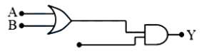
(B) The given logic circuit consists of an $OR$ gate followed by an $AND$ gate. Let the output of the $OR$ gate be $X$. Then $X = A + B$.
The final output $Y$ is obtained from the $AND$ gate,where $Y = X \cdot C = (A + B) \cdot C$.
For the output $Y$ to be $1$,both inputs to the $AND$ gate must be $1$. Therefore,$X = 1$ and $C = 1$.
Since $X = A + B = 1$,at least one of $A$ or $B$ must be $1$.
Checking the options:
$A) A=1, B=0, C=0 \implies Y = (1+0) \cdot 0 = 0$
$B) A=1, B=0, C=1 \implies Y = (1+0) \cdot 1 = 1$
$C) A=1, B=1, C=0 \implies Y = (1+1) \cdot 0 = 0$
$D) A=0, B=0, C=1 \implies Y = (0+0) \cdot 1 = 0$
Thus,option $B$ is correct.
0 likes
View Solution368
EasyMCQ
The Boolean expression for a two-input Ex-$OR$ gate is (where $A$ and $B$ are inputs,and $Y$ is the output):
A
$Y=(\bar{A}+B) \cdot(A+\bar{B})$
B
$Y=(A \cdot B)+(\bar{A}+\bar{B})$
C
$Y=(\bar{A} \cdot B)+(A \cdot \bar{B})$
D
$Y=(A \cdot B)+(\bar{A}+B)$
Solution
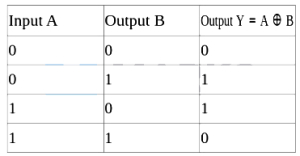
(C) The truth table for an Ex-$OR$ gate is as follows:
| Input $A$ | Input $B$ | Output $Y = A \oplus B$ |
| :--- | :--- | :--- |
| $0$ | $0$ | $0$ |
| $0$ | $1$ | $1$ |
| $1$ | $0$ | $1$ |
| $1$ | $1$ | $0$ |
The output equation for an Ex-$OR$ gate is $Y = A \oplus B = (\bar{A} \cdot B) + (A \cdot \bar{B})$.
Key points to remember:
$(1)$ The output is low $(0)$ when both inputs are the same.
$(2)$ The output is high $(1)$ when both inputs are different.
0 likes
View Solution369
EasyMCQ
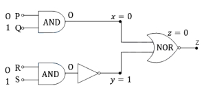
$A$ combination of logic gates is as shown in the figure. $P$,$Q$,$R$,and $S$ are the inputs and $X$,$Y$,and $Z$ are outputs. When inputs $P$ and $R$ are 'low' $(0)$ and $Q$ and $S$ are 'high' $(1)$,the outputs $X$,$Y$,and $Z$ are respectively:
A
$0, 1, 0$
B
$0, 1, 1$
C
$1, 0, 0$
D
$1, 1, 1$
Solution
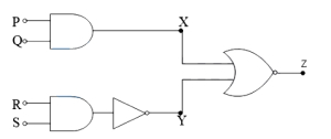
(A) Given inputs are $P = 0$,$Q = 1$,$R = 0$,and $S = 1$.
$1$. The output $X$ is obtained from an $AND$ gate with inputs $P$ and $Q$. Thus,$X = P \cdot Q = 0 \cdot 1 = 0$.
$2$. The input to the $NOT$ gate is the output of an $AND$ gate with inputs $R$ and $S$. Let this be $W$. So,$W = R \cdot S = 0 \cdot 1 = 0$. The output $Y$ is the $NOT$ of $W$,so $Y = \overline{W} = \overline{0} = 1$.
$3$. The output $Z$ is obtained from a $NOR$ gate with inputs $X$ and $Y$. Thus,$Z = \overline{X + Y} = \overline{0 + 1} = \overline{1} = 0$.
Therefore,the outputs are $X = 0$,$Y = 1$,and $Z = 0$.
0 likes
View Solution370
EasyMCQ
The truth table for the two-input Ex-$OR$ gate is (where $A$ and $B$ are the inputs and $Y$ is the output).
| $A$ | $B$ | $Y$ |
|---|---|---|
| $0$ | $0$ | $0$ |
| $0$ | $1$ | $1$ |
| $1$ | $0$ | $1$ |
| $1$ | $1$ | $0$ |
A
Table $(P)$
B
Table $(Q)$
C
Table $(R)$
D
Table $(S)$
Solution
(D) The Boolean expression for an Exclusive-$OR$ (Ex-$OR$) gate is given by:
$Y = A \oplus B = \bar{A} \cdot B + A \cdot \bar{B}$
The output of an Ex-$OR$ gate is $HIGH$ $(1)$ only when the inputs are at different logic levels. If both inputs are the same ($0,0$ or $1,1$),the output is $LOW$ $(0)$.
Evaluating the truth table:
$1$. For $A=0, B=0$: $Y = 0 \oplus 0 = 0$
$2$. For $A=0, B=1$: $Y = 0 \oplus 1 = 1$
$3$. For $A=1, B=0$: $Y = 1 \oplus 0 = 1$
$4$. For $A=1, B=1$: $Y = 1 \oplus 1 = 0$
Comparing this with the given tables,Table $(S)$ matches this truth table.
0 likes
View Solution371
EasyMCQ
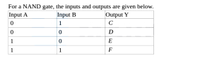
For a $NAND$ gate, the inputs and outputs are given in the table below. The values taken by $C, D, E, F$ are respectively:
| Input $A$ | Input $B$ | Output $Y$ |
|---|---|---|
| $0$ | $1$ | $C$ |
| $0$ | $0$ | $D$ |
| $1$ | $0$ | $E$ |
| $1$ | $1$ | $F$ |
A
$0, 1, 0, 0$
B
$1, 1, 1, 0$
C
$0, 1, 0, 1$
D
$1, 0, 1, 1$
Solution
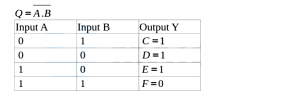
(B) The Boolean expression for a $NAND$ gate is $Y = \overline{A \cdot B}$.
$1$. For $A = 0, B = 1$: $Y = \overline{0 \cdot 1} = \overline{0} = 1$. Thus, $C = 1$.
$2$. For $A = 0, B = 0$: $Y = \overline{0 \cdot 0} = \overline{0} = 1$. Thus, $D = 1$.
$3$. For $A = 1, B = 0$: $Y = \overline{1 \cdot 0} = \overline{0} = 1$. Thus, $E = 1$.
$4$. For $A = 1, B = 1$: $Y = \overline{1 \cdot 1} = \overline{1} = 0$. Thus, $F = 0$.
Therefore, the values are $C = 1, D = 1, E = 1, F = 0$.
0 likes
View Solution372
EasyMCQ
The combination of logic gates shown below becomes:
A
$X-OR$ gate
B
$NAND$ gate
C
$NOR$ gate
D
$OR$ gate
Solution
(D) The given circuit consists of two $NAND$ gates used as $NOT$ gates (since their inputs are shorted) followed by a $NAND$ gate.
Let the inputs be $A$ and $B$.
The output of the first $NAND$ gate (acting as $NOT$) is $\bar{A}$.
The output of the second $NAND$ gate (acting as $NOT$) is $\bar{B}$.
These two outputs are fed into a third $NAND$ gate.
The final output $Y$ is given by $Y = \overline{(\bar{A} \cdot \bar{B})}$.
Using De Morgan's theorem,$\overline{(\bar{A} \cdot \bar{B})} = \overline{\bar{A}} + \overline{\bar{B}} = A + B$.
This is the Boolean expression for an $OR$ gate.
Therefore,the combination acts as an $OR$ gate.
0 likes
View Solution373
EasyMCQ
The output of an $OR$ gate is $1$.
A
only when both inputs are $1$.
B
only when both inputs are $0$.
C
only when either input is $0$.
D
if either or both inputs are $1$.
Solution
(D) An $OR$ gate performs the logical addition operation. The Boolean expression for an $OR$ gate with inputs $A$ and $B$ is $Y = A + B$.
According to the truth table of an $OR$ gate:
- If $A = 0$ and $B = 0$,then $Y = 0$.
- If $A = 0$ and $B = 1$,then $Y = 1$.
- If $A = 1$ and $B = 0$,then $Y = 1$.
- If $A = 1$ and $B = 1$,then $Y = 1$.
Therefore,the output is $1$ if either input $A$ or input $B$ (or both) is $1$.
According to the truth table of an $OR$ gate:
- If $A = 0$ and $B = 0$,then $Y = 0$.
- If $A = 0$ and $B = 1$,then $Y = 1$.
- If $A = 1$ and $B = 0$,then $Y = 1$.
- If $A = 1$ and $B = 1$,then $Y = 1$.
Therefore,the output is $1$ if either input $A$ or input $B$ (or both) is $1$.
0 likes
View Solution374
EasyMCQ
Two different logic gates giving output '$0$' for the inputs $(0,1)$ and $(1,0)$ are
A
'$AND$','$NAND$'
B
'$NAND$','$NOR$'
C
'$OR$','$AND$'
D
'$NOR$','$AND$'
Solution
(D) For an $AND$ gate,the output is $1$ only if both inputs are $1$. For inputs $(0,1)$ and $(1,0)$,the output is $0$.
For an $OR$ gate,the output is $0$ only if both inputs are $0$. For inputs $(0,1)$ and $(1,0)$,the output is $1$.
For a $NAND$ gate,the output is $0$ only if both inputs are $1$. For inputs $(0,1)$ and $(1,0)$,the output is $1$.
For a $NOR$ gate,the output is $1$ only if both inputs are $0$. For inputs $(0,1)$ and $(1,0)$,the output is $0$.
Thus,both $AND$ and $NOR$ gates provide an output of $0$ for the given input combinations $(0,1)$ and $(1,0)$.
0 likes
View Solution375
EasyMCQ
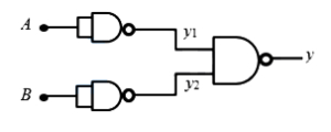
The combination of $NAND$ gates is shown in the figure. It is equivalent to which gate?
A
$NOR$ gate
B
$AND$ gate
C
$OR$ gate
D
$X$-$OR$ gate
Solution
(C) The two $NAND$ gates whose inputs are joined together act as $NOT$ gates. Let the inputs be $A$ and $B$. The outputs of the first two $NAND$ gates are $y_1 = \overline{A}$ and $y_2 = \overline{B}$. These are fed into the third $NAND$ gate. The final output is $y = \overline{y_1 \cdot y_2} = \overline{\overline{A} \cdot \overline{B}}$. By De Morgan's theorem, $y = \overline{\overline{A}} + \overline{\overline{B}} = A + B$. This is the Boolean expression for an $OR$ gate. The truth table is as follows:
| $A$ | $B$ | $y_1$ | $y_2$ | $y$ |
|---|---|---|---|---|
| $0$ | $0$ | $1$ | $1$ | $0$ |
| $0$ | $1$ | $1$ | $0$ | $1$ |
| $1$ | $0$ | $0$ | $1$ | $1$ |
| $1$ | $1$ | $0$ | $0$ | $1$ |
Thus, the combination is equivalent to an $OR$ gate.
| $A$ | $B$ | $y_1$ | $y_2$ | $y$ |
|---|---|---|---|---|
| $0$ | $0$ | $1$ | $1$ | $0$ |
| $0$ | $1$ | $1$ | $0$ | $1$ |
| $1$ | $0$ | $0$ | $1$ | $1$ |
| $1$ | $1$ | $0$ | $0$ | $1$ |
Thus, the combination is equivalent to an $OR$ gate.
0 likes
View Solution376
EasyMCQ
$A$ logic gate which gives output '$HIGH$' only when its two input terminals are at different logic levels with respect to each other is
A
$NOR$ gate
B
$OR$ gate
C
$AND$ gate
D
$X$-$OR$ gate
Solution
(D) The $X-OR$ (Exclusive-$OR$) gate is a digital logic gate that implements exclusive disjunction.
Its output is '$HIGH$' $(1)$ if and only if the inputs are different (i.e.,one input is $0$ and the other is $1$).
If both inputs are the same ($0,0$ or $1,1$),the output is '$LOW$' $(0)$.
Therefore,the $X-OR$ gate satisfies the condition of giving a '$HIGH$' output only when its two input terminals are at different logic levels.
0 likes
View Solution377
EasyMCQ
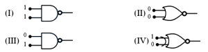
Which of the following logic gates will give an output of ' $1$ ' for the given inputs?
A
$II$ and $III$
B
$I$ and $IV$
C
$I$ and $III$
D
$II$ and $IV$
Solution
(A) Let us analyze each gate based on its truth table:
$(I)$ The gate is a $NAND$ gate with inputs $1, 1$. The output is $Y = \overline{A \cdot B} = \overline{1 \cdot 1} = \overline{1} = 0$.
$(II)$ The gate is a $NOR$ gate with inputs $0, 0$. The output is $Y = \overline{A + B} = \overline{0 + 0} = \overline{0} = 1$.
$(III)$ The gate is a $NAND$ gate with inputs $0, 1$. The output is $Y = \overline{A \cdot B} = \overline{0 \cdot 1} = \overline{0} = 1$.
$(IV)$ The gate is an $EX$-$NOR$ gate with inputs $1, 0$. The output is $Y = A \odot B = 1 \odot 0 = 0$.
Thus,gates $II$ and $III$ provide an output of ' $1$ '.
0 likes
View Solution378
EasyMCQ
For the output of the following logic circuit to be ' $1$ ', the values of inputs $A$ and $B$ should be respectively
A
$0$ and $1$
B
$0$ and $0$
C
$1$ and $1$
D
$1$ and $0$
Solution
(B) The given circuit consists of an $OR$ gate followed by a $NOT$ gate, which together form a $NOR$ gate.
Let the output of the $OR$ gate be $Y'$. The output of the $NOR$ gate is $Y = \overline{A + B}$.
For the final output $Y$ to be '$1$', the input to the $NOT$ gate must be '$0$'.
This means the output of the $OR$ gate $Y' = A + B$ must be '$0$'.
An $OR$ gate gives an output of '$0$' only when both its inputs are '$0$'.
Therefore, $A = 0$ and $B = 0$.
0 likes
View Solution379
EasyMCQ
The Boolean equation for the circuit given in the figure is
A
$Y=A+\bar{B}$
B
$Y=\overline{A+B}$
C
$Y=\bar{A}+B$
D
$Y=\bar{A}+\bar{B}$
Solution
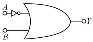
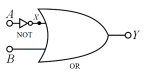
(C) In the given circuit,we have a combination of a $NOT$ gate and an $OR$ gate.
For the $NOT$ gate,the input is $A$,so the output is $X = \bar{A}$.
This output $X$ acts as one of the inputs to the $OR$ gate,while $B$ is the other input.
For the $OR$ gate,the output $Y$ is the sum of its inputs:
$Y = X + B$
Substituting the value of $X$ from the $NOT$ gate:
$Y = \bar{A} + B$
Thus,the Boolean expression for the given circuit is $Y = \bar{A} + B$.
0 likes
View Solution380
EasyMCQ
For a two-input $AND$ gate,the four entries are shown in the truth table. Identify the correct ones out of these ($A, B =$ input,$Y =$ output).
| Entry | $A$ | $B$ | $Y$ |
|---|---|---|---|
| $1$ | $0$ | $1$ | $0$ |
| $2$ | $1$ | $0$ | $0$ |
| $3$ | $1$ | $1$ | $1$ |
| $4$ | $0$ | $0$ | $1$ |

A
$1$ and $2$ only
B
$1, 2$ and $3$ only
C
$1, 3$ and $4$ only
D
$2, 3$ and $4$ only
Solution
(B) The logic operation for an $AND$ gate is defined by the Boolean expression $Y = A \cdot B$.
This means the output $Y$ is $1$ only if both inputs $A$ and $B$ are $1$. Otherwise,the output $Y$ is $0$.
Let us evaluate the given entries:
Entry $1$: $A=0, B=1$. $Y = 0 \cdot 1 = 0$. This is correct.
Entry $2$: $A=1, B=0$. $Y = 1 \cdot 0 = 0$. This is correct.
Entry $3$: $A=1, B=1$. $Y = 1 \cdot 1 = 1$. This is correct.
Entry $4$: $A=0, B=0$. $Y = 0 \cdot 0 = 0$. The table shows $Y=1$,which is incorrect.
Therefore,entries $1, 2,$ and $3$ are correct.
0 likes
View Solution381
EasyMCQ
The resultant gate and its Boolean expression for the given circuit is
A
$OR, A+B$
B
$NAND, \overline{A \cdot B}$
C
$NOR, \overline{A+B}$
D
$AND, A \cdot B$
Solution
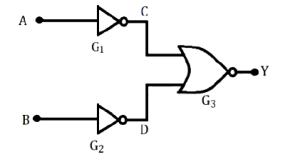
(D) The given circuit consists of two $NOT$ gates ($G_1$ and $G_2$) and one $NOR$ gate $(G_3)$.
$1$. The input $A$ passes through the $NOT$ gate $G_1$,so the output at $C$ is $C = \overline{A}$.
$2$. The input $B$ passes through the $NOT$ gate $G_2$,so the output at $D$ is $D = \overline{B}$.
$3$. These outputs $C$ and $D$ are fed into the $NOR$ gate $G_3$. The output $Y$ of a $NOR$ gate is the complement of the $OR$ of its inputs.
$4$. Therefore,$Y = \overline{C + D}$.
$5$. Substituting the values of $C$ and $D$,we get $Y = \overline{\overline{A} + \overline{B}}$.
$6$. According to De Morgan's theorem,$\overline{\overline{A} + \overline{B}} = \overline{\overline{A}} \cdot \overline{\overline{B}} = A \cdot B$.
$7$. The Boolean expression $Y = A \cdot B$ represents an $AND$ gate.
Thus,the resultant gate is an $AND$ gate with the expression $A \cdot B$.
0 likes
View Solution382
EasyMCQ
For which logic gate is the following statement true? The output is high if and only if all inputs are high.
A
$AND$
B
$OR$
C
$NOR$
D
$NAND$
Solution
(A) The logic gate for which the output is high $(1)$ if and only if all inputs are high $(1)$ is the $AND$ gate.
For an $AND$ gate with inputs $A$ and $B$,the output $Y$ is given by $Y = A \cdot B$.
If $A = 1$ and $B = 1$,then $Y = 1 \cdot 1 = 1$.
For any other combination of inputs,the output is low $(0)$.
For an $AND$ gate with inputs $A$ and $B$,the output $Y$ is given by $Y = A \cdot B$.
If $A = 1$ and $B = 1$,then $Y = 1 \cdot 1 = 1$.
For any other combination of inputs,the output is low $(0)$.
0 likes
View Solution383
EasyMCQ
How many $NAND$ gates are required to form an $AND$ gate?
A
$1$
B
$2$
C
$3$
D
$4$
Solution
(B) To form an $AND$ gate using $NAND$ gates,we first pass the inputs $A$ and $B$ through a $NAND$ gate to get $\overline{A \cdot B}$.
Then,we pass this output through another $NAND$ gate configured as a $NOT$ gate (by shorting its inputs together).
Let the output of the first $NAND$ gate be $X = \overline{A \cdot B}$.
The second $NAND$ gate acts as a $NOT$ gate,so its output $Y = \overline{X \cdot X} = \overline{X} = \overline{\overline{A \cdot B}} = A \cdot B$.
Thus,two $NAND$ gates are required to form an $AND$ gate.
0 likes
View Solution384
MediumMCQ
When the two inputs of a $NAND$ gate are shorted,the resulting gate is
A
$NOR$
B
$OR$
C
$NOT$
D
$AND$
Solution
(C) $NAND$ gate is defined as an $AND$ gate followed by a $NOT$ gate. The Boolean expression for a $NAND$ gate with inputs $A$ and $B$ is $Y = \overline{A \cdot B}$.
When the two inputs are shorted,$A = B$. Substituting this into the expression,we get $Y = \overline{A \cdot A} = \overline{A}$.
This is the Boolean expression for a $NOT$ gate.
The truth table for this configuration is:
Since the output is the inverse of the input,the resulting gate is a $NOT$ gate.
When the two inputs are shorted,$A = B$. Substituting this into the expression,we get $Y = \overline{A \cdot A} = \overline{A}$.
This is the Boolean expression for a $NOT$ gate.
The truth table for this configuration is:
| $A$ | $Y = \overline{A \cdot A}$ |
| $0$ | $1$ |
| $1$ | $0$ |
Since the output is the inverse of the input,the resulting gate is a $NOT$ gate.
0 likes
View Solution385
EasyMCQ
The given truth table is for:
| $A$ | $B$ | $Y$ |
|---|---|---|
| $0$ | $0$ | $1$ |
| $0$ | $1$ | $1$ |
| $1$ | $0$ | $1$ |
| $1$ | $1$ | $0$ |
A
$AND$ gate
B
$OR$ gate
C
$NAND$ gate
D
$NOR$ gate
Solution
(C) truth table defines the output of a logic gate for all possible input combinations.
For the given table:
- When $A=0, B=0$,output $Y=1$.
- When $A=0, B=1$,output $Y=1$.
- When $A=1, B=0$,output $Y=1$.
- When $A=1, B=1$,output $Y=0$.
This behavior corresponds to the $NAND$ gate,which is the inverse of the $AND$ gate. The Boolean expression for a $NAND$ gate is $Y = \overline{A \cdot B}$.
0 likes
View Solution386
MediumMCQ
For the given digital circuit, identify the logic gate it represents:
A
$OR$-Gate
B
$NOR$-Gate
C
$NAND$-Gate
D
$AND$-Gate
Solution
(D) The given circuit consists of two $NOR$ gates acting as $NOT$ gates, followed by a $NOR$ gate. Let the inputs be $A$ and $B$.
The first two gates are $NOR$ gates with both inputs tied together. The output of the first gate is $\overline{A+A} = \bar{A}$.
The output of the second gate is $\overline{B+B} = \bar{B}$.
These outputs are fed into the final $NOR$ gate. The output $Y$ is given by:
$Y = \overline{\bar{A} + \bar{B}}$
Using De Morgan's theorem, $\overline{\bar{A} + \bar{B}} = \overline{\bar{A}} \cdot \overline{\bar{B}} = A \cdot B$.
Thus, the circuit represents an $AND$ gate.
| $A$ | $B$ | $Y = A \cdot B$ |
| $0$ | $0$ | $0$ |
| $0$ | $1$ | $0$ |
| $1$ | $0$ | $0$ |
| $1$ | $1$ | $1$ |
0 likes
View Solution387
MediumMCQ
The truth table for the given circuit is
A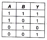
B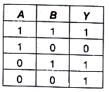
C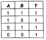
D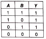
Solution
(D) The given logic circuit consists of a $NOR$ gate and an $AND$ gate whose output is fed into a $NAND$ gate. Let the inputs be $A$ and $B$.
$1$. The output of the $NOR$ gate is $\overline{A+B}$.
$2$. The output of the $AND$ gate is $A \cdot B$.
$3$. These two outputs are fed into a $NAND$ gate. The final output $Y$ is given by:
$Y = \overline{(\overline{A+B}) \cdot (A \cdot B)}$
Using De Morgan's law,$\overline{X \cdot Y} = \overline{X} + \overline{Y}$:
$Y = \overline{(\overline{A+B})} + \overline{(A \cdot B)}$
$Y = (A+B) + (\overline{A} + \overline{B})$
$Y = (A + \overline{A}) + (B + \overline{B})$
Since $A + \overline{A} = 1$ and $B + \overline{B} = 1$:
$Y = 1 + 1 = 1$
Thus,the output $Y$ is always $1$ for all combinations of inputs $A$ and $B$. Therefore,the truth table will have $1$ in all rows for output $Y$. Comparing this with the given options,option $(D)$ is correct.
0 likes
View Solution388
EasyMCQ
The circuit given represents which of the logic operations?
A
$OR$
B
$AND$
C
$NOT$
D
$NOR$
Solution
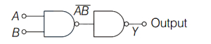
(B) The given circuit consists of two $NAND$ gates connected in series,where the second $NAND$ gate acts as a $NOT$ gate because its inputs are shorted together.
Let the inputs to the first $NAND$ gate be $A$ and $B$. The output of the first $NAND$ gate is $\overline{A \cdot B}$.
This output is fed as the input to the second $NAND$ gate. Since both inputs of the second $NAND$ gate are connected to the same signal,its output $Y$ is given by:
$Y = \overline{(\overline{A \cdot B}) \cdot (\overline{A \cdot B})}$
Using the property of Boolean algebra $\overline{X \cdot X} = \overline{X}$,we get:
$Y = \overline{(\overline{A \cdot B})} = A \cdot B$
Thus,the circuit performs the operation of an $AND$ gate.
0 likes
View Solution389
EasyMCQ
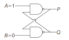
In the following circuit, what are the values of $P$ and $Q$?
A
$P=1, Q=0$
B
$P=0, Q=1$
C
$P=0, Q=0$
D
$P=1, Q=1$
Solution
(B) The circuit consists of two cross-coupled $NAND$ gates, forming an $S-R$ latch.
Let the inputs be $S=1$ and $R=0$.
The output $P$ is given by $P = \overline{1 \cdot Q} = \overline{Q}$.
The output $Q$ is given by $Q = \overline{0 \cdot P} = \overline{0} = 1$.
Since $Q=1$, substituting this into the equation for $P$ gives $P = \overline{1} = 0$.
Thus, the stable state of the circuit is $P=0$ and $Q=1$.
0 likes
View Solution390
EasyMCQ
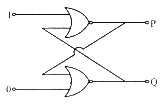
In the following circuit,what are $P$ and $Q$?
A
$P=0, Q=1$
B
$P=0, Q=0$
C
$P=1, Q=1$
D
$P=1, Q=0$
Solution
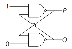
(A) The circuit consists of two cross-coupled $NOR$ gates forming an $SR$ latch.
For a $NOR$ gate,the output $Y = \overline{A+B}$.
Let the top gate be Gate $1$ and the bottom gate be Gate $2$.
The inputs to Gate $1$ are $1$ and $Q$. Thus,$P = \overline{1+Q} = 0$.
The inputs to Gate $2$ are $0$ and $P$. Thus,$Q = \overline{0+P}$.
Substituting $P=0$ into the equation for $Q$,we get $Q = \overline{0+0} = \overline{0} = 1$.
Therefore,$P=0$ and $Q=1$.
0 likes
View Solution391
EasyMCQ
If $ A=1 $ and $ B=0 $,then in terms of Boolean algebra,$ \bar{A}+B= $
A
$ B $
B
$ \bar{B} $
C
$ A $
D
$ \bar{A} $
Solution
(A) Given $ A=1 $ and $ B=0 $.
In Boolean algebra,the complement of $ A $ is $ \bar{A} = \bar{1} = 0 $.
Now,substitute the values into the expression $ \bar{A}+B $:
$ \bar{A}+B = 0 + 0 = 0 $.
Since $ B=0 $,we can see that $ \bar{A}+B = B $.
Therefore,the correct option is $ A $.
In Boolean algebra,the complement of $ A $ is $ \bar{A} = \bar{1} = 0 $.
Now,substitute the values into the expression $ \bar{A}+B $:
$ \bar{A}+B = 0 + 0 = 0 $.
Since $ B=0 $,we can see that $ \bar{A}+B = B $.
Therefore,the correct option is $ A $.
0 likes
View Solution392
EasyMCQ
The output of an $OR$ gate is connected to both the inputs of a $NAND$ gate. The combination will serve as
A
$AND$ gate
B
$NOT$ gate
C
$NAND$ gate
D
$NOR$ gate
Solution
(D) Let the inputs of the $OR$ gate be $A$ and $B$. The output of the $OR$ gate is $Y = A + B$.
This output $Y$ is connected to both inputs of a $NAND$ gate. Let the inputs of the $NAND$ gate be $X_1$ and $X_2$,where $X_1 = X_2 = Y = A + B$.
The output of a $NAND$ gate with inputs $X_1$ and $X_2$ is given by $\overline{X_1 \cdot X_2}$.
Substituting $X_1 = X_2 = A + B$,the final output $Y^{\prime}$ is $\overline{(A + B) \cdot (A + B)}$.
Using the Boolean identity $X \cdot X = X$,we get $Y^{\prime} = \overline{A + B}$.
The expression $\overline{A + B}$ represents the Boolean operation of a $NOR$ gate.
Therefore,the combination acts as a $NOR$ gate.
0 likes
View Solution393
EasyMCQ
The following truth table with $A$ and $B$ as inputs is for which logic gate?
| $A$ | $B$ | Output |
|---|---|---|
| $1$ | $0$ | $1$ |
| $1$ | $1$ | $0$ |
| $0$ | $1$ | $1$ |
| $0$ | $0$ | $0$ |
A
$NOR$
B
$AND$
C
$OR$
D
$XOR$
Solution
(D) Let us analyze the truth table provided:
$1$. When $A=1, B=0$,Output = $1$.
$2$. When $A=1, B=1$,Output = $0$.
$3$. When $A=0, B=1$,Output = $1$.
$4$. When $A=0, B=0$,Output = $0$.
Comparing this with standard logic gates:
- For an $XOR$ gate,the output is $1$ only when the inputs are different $(A \neq B)$.
- In this table,the output is $1$ when $(A=1, B=0)$ or $(A=0, B=1)$,and $0$ when $(A=1, B=1)$ or $(A=0, B=0)$.
- This behavior perfectly matches the $XOR$ gate (Exclusive-$OR$ gate),which follows the Boolean expression $Y = A \oplus B$.
0 likes
View Solution394
MediumMCQ
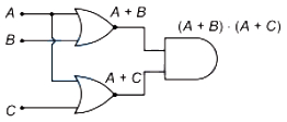
The output of the given logic circuit is
A
$A \cdot(B+C)$
B
$A \cdot(B \cdot C)$
C
$(A+B) \cdot(A+C)$
D
$A+B+C$
Solution
(C) The given circuit consists of two $OR$ gates followed by an $AND$ gate.
$1$. The inputs to the first $OR$ gate are $A$ and $B$. Therefore,its output is $(A+B)$.
$2$. The inputs to the second $OR$ gate are $A$ and $C$. Therefore,its output is $(A+C)$.
$3$. These two outputs $(A+B)$ and $(A+C)$ are fed as inputs to the final $AND$ gate.
$4$. The output $Y$ of the $AND$ gate is the product of its inputs: $Y = (A+B) \cdot (A+C)$.
0 likes
View Solution395
EasyMCQ
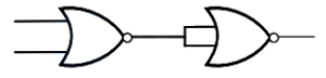
Identify the logic operation performed by the circuit given here.
A
$OR$
B
$NOR$
C
$NOT$
D
$NAND$
Solution
(A) The given circuit consists of a $NOR$ gate followed by a $NOR$ gate with its inputs shorted together,which acts as a $NOT$ gate.
Let the inputs to the first $NOR$ gate be $A$ and $B$. The output of the first $NOR$ gate is $Y' = \overline{A+B}$.
This output $Y'$ is fed into both inputs of the second $NOR$ gate. The output of the second $NOR$ gate is $Y = \overline{Y' + Y'} = \overline{Y'} = \overline{\overline{A+B}}$.
Using the law of double negation,$\overline{\overline{X}} = X$,we get $Y = A+B$.
This is the Boolean expression for an $OR$ gate.
0 likes
View Solution396
MediumMCQ
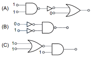
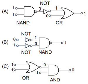
In the following combinations of logic gates,the outputs of $A, B$ and $C$ are respectively
A
$1, 1, 0$
B
$0, 1, 0$
C
$1, 0, 1$
D
$0, 1, 1$
Solution
(A) For circuit $A$: The inputs to the $NAND$ gate are $1$ and $1$,so its output is $0$. This $0$ passes through a $NOT$ gate,becoming $1$. The $OR$ gate receives inputs $1$ and $0$,resulting in an output of $1$.
For circuit $B$: The inputs $0$ and $1$ pass through $NOT$ gates,becoming $1$ and $0$ respectively. These are inputs to a $NAND$ gate. Since $1 \text{ AND } 0 = 0$,the $NAND$ gate (which is $NOT$-$AND$) outputs $1$.
For circuit $C$: The $OR$ gate receives inputs $1$ and $1$,resulting in an output of $1$. However,the diagram shows the $OR$ gate is followed by a $NOT$ bubble (making it a $NOR$ gate),so the output is $0$. This $0$ and the input $1$ are fed into an $AND$ gate,resulting in an output of $0$.
Thus,the outputs are $1, 1, 0$ respectively.
0 likes
View Solution397
EasyMCQ
To get an output $Y=1$ from the circuit shown,the inputs $A, B,$ and $C$ must be respectively:
A
$0, 1, 0$
B
$1, 0, 0$
C
$1, 0, 1$
D
$1, 1, 0$
Solution
(C) The given circuit consists of an $OR$ gate followed by an $AND$ gate. The Boolean expression for the output $Y$ is given by $Y = (A + B) \cdot C$.
For the output to be $Y = 1$,both inputs to the $AND$ gate must be $1$. Therefore,$(A + B) = 1$ and $C = 1$.
Checking the options:
For option $C$: $A = 1, B = 0, C = 1$.
Substituting these values: $Y = (1 + 0) \cdot 1 = 1 \cdot 1 = 1$.
Thus,the inputs $A = 1, B = 0, C = 1$ result in an output $Y = 1$.
0 likes
View Solution398
EasyMCQ
The truth table given below is for ($A$ and $B$ are the inputs,$Y$ is the output).
| $A$ | $B$ | $Y$ |
|---|---|---|
| $0$ | $0$ | $1$ |
| $0$ | $1$ | $1$ |
| $1$ | $0$ | $1$ |
| $1$ | $1$ | $0$ |
A
$NOR$
B
$AND$
C
$XOR$
D
$NAND$
Solution
(D) The given truth table shows that the output $Y$ is $1$ when either $A$ or $B$ or both are $0$,and the output $Y$ is $0$ only when both inputs $A$ and $B$ are $1$.
This behavior corresponds to the Boolean expression $Y = \overline{A \cdot B}$.
This is the characteristic truth table of a $NAND$ gate,which is an $AND$ gate followed by a $NOT$ gate.
This behavior corresponds to the Boolean expression $Y = \overline{A \cdot B}$.
This is the characteristic truth table of a $NAND$ gate,which is an $AND$ gate followed by a $NOT$ gate.
0 likes
View Solution399
EasyMCQ
Which of the following logic gates is considered as 'universal'?
A
B
C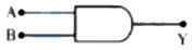
D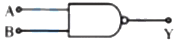
Solution
(D) universal gate is a logic gate that can be used to implement any other logic gate without the need for any other type of gate. The $NAND$ gate and the $NOR$ gate are known as universal gates. In the given options,the $NAND$ gate is a universal gate because any basic logic gate ($AND$,$OR$,$NOT$) can be constructed using only $NAND$ gates.
0 likes
View Solution400
MediumMCQ
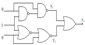
If five logic gates are connected as shown in the figure,then the values of $y_1, y_2$ and $y_3$ are respectively
A
$1$,$1$,$1$
B
$0$,$0$,$1$
C
$1$,$1$,$0$
D
$1$,$0$,$1$
Solution
(A) Let the inputs be $A=0, B=1, C=0$.
$1$. The top $NAND$ gate has inputs $A=0$ and $B=1$. Its output is $\overline{0 \cdot 1} = \overline{0} = 1$.
$2$. The second $NAND$ gate has inputs $A=0$ and the output of the first $NAND$ gate $(1)$. Its output $y_1 = \overline{0 \cdot 1} = \overline{0} = 1$.
$3$. The bottom $NOR$ gate has inputs $B=1$ and $C=0$. Its output is $\overline{1 + 0} = \overline{1} = 0$.
$4$. The second $NOR$ gate has inputs $C=0$ and the output of the first $NOR$ gate $(0)$. Its output $y_2 = \overline{0 + 0} = \overline{0} = 1$.
$5$. The final $OR$ gate has inputs $y_1=1$ and $y_2=1$. Its output $y_3 = 1 + 1 = 1$.
Thus,the values are $y_1=1, y_2=1, y_3=1$.
0 likes
View SolutionSemiconductor Electronics — Boolean Algebra and Logic Gates · Frequently Asked Questions
1Are these Semiconductor Electronics questions useful for JEE and NEET?
Yes. All questions in this section are mapped to JEE Main and NEET exam patterns. Previous year questions from JEE Main, NEET, GUJCET and state-level exams are included with full solutions.
2Can I switch to Hindi or Gujarati for these questions?
Yes. Use the language tabs in the hero section or the sidebar to view the same questions and solutions in English, Hindi or Gujarati.
3How do I generate a question paper from this subtopic?
Use the Vedclass Exam Paper Generator — select the chapter and subtopic, set difficulty, and generate Sets A, B, C, D automatically. First 3 chapters of every subject are free.
Vedclass Products
For Students
Vedclass Test Series
Mock tests in real JEE/NEET style with performance analysis. 5-day free trial.
Start Free TrialFor Teachers
Exam Paper Generator
Generate Set A/B/C/D papers from this chapter in 2 minutes. 3 chapters free.
Try FreeFor Institutes
Online Exam Module
Live online exams with unlimited students, 360° analytics & white-label branding.
See DemoFor Teachers & Institutes
Generate a Semiconductor Electronics Exam Paper in 2 Minutes
Select subtopic & difficulty — Sets A, B, C, D auto-generated with No Repeat logic.
First 3 chapters of every subject are free — no payment required.