
A English
Charging and Discharging of Capacitance and RC circuit (DC) Questions in English
Class 12 Physics · Electric Potential and Capacitance · Charging and Discharging of Capacitance and RC circuit (DC)
139+
Questions
English
Language
100%
With Solutions
Showing 49 of 139 questions in English
1
MediumMCQ
Dimensions of $CR$ are those of
A
Frequency
B
Energy
C
Time period
D
Current
Solution
(C) The dimension of $CR$ is given by the product of capacitance $(C)$ and resistance $(R)$.
$C = \frac{Q}{V}$,where $Q$ is charge and $V$ is potential difference.
$R = \frac{V}{I}$,where $I$ is current.
Therefore,$CR = \left( \frac{Q}{V} \right) \times \left( \frac{V}{I} \right) = \frac{Q}{I}$.
Since $I = \frac{Q}{t}$,where $t$ is time,we have $\frac{Q}{I} = t$.
Thus,the dimensions of $CR$ are the same as those of time,which corresponds to the time period.
0 likes
View Solution2
MediumMCQ
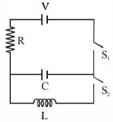
$A$ light bulb,a capacitor,and a battery are connected in a series circuit as shown in the figure,with switch $S$ initially open. When the switch $S$ is closed,which one of the following is true?

A
The bulb will light up for an instant when the capacitor starts charging.
B
The bulb will light up when the capacitor is fully charged.
C
The bulb will not light up at all.
D
The bulb will light up and go off at regular intervals.
Solution
(A) When the switch $S$ is closed,the capacitor begins to charge.
Initially,the capacitor acts as a short circuit (zero resistance),allowing current to flow through the circuit,which causes the bulb to light up for an instant.
As the capacitor charges,the potential difference across it increases,and the current in the circuit decreases.
Once the capacitor is fully charged,it acts as an open circuit,blocking the flow of direct current $(DC)$.
Therefore,the current becomes zero,and the bulb stops glowing.
0 likes
View Solution3
EasyMCQ
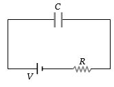
As shown in the figure,if a capacitor $C$ is charged by connecting it with a battery of voltage $V$ through a resistance $R$,then the energy supplied by the battery will be:
A
$\frac{1}{2}CV^2$
B
More than $\frac{1}{2}CV^2$
C
Less than $\frac{1}{2}CV^2$
D
Zero
Solution
(B) When a capacitor $C$ is charged by a battery of voltage $V$ through a resistance $R$,the total charge that flows from the battery is $Q = CV$.
The total work done by the battery is $W = QV = (CV)V = CV^2$.
The energy stored in the capacitor is $U = \frac{1}{2}CV^2$.
Since the energy supplied by the battery is $CV^2$ and the energy stored in the capacitor is $\frac{1}{2}CV^2$,the remaining energy $\frac{1}{2}CV^2$ is dissipated as heat in the resistance $R$.
Therefore,the energy supplied by the battery is $CV^2$,which is more than the energy stored in the capacitor,$\frac{1}{2}CV^2$.
0 likes
View Solution4
EasyMCQ
When a lamp is connected in series with a capacitor,then:
A
Lamp will not glow
B
Lamp will burst out
C
Lamp will glow normally
D
None of these
Solution
(A) When a lamp is connected in series with a capacitor to a $D.C.$ source,the capacitor gets charged and eventually blocks the flow of current once it is fully charged.
Since $D.C.$ cannot pass through a capacitor,the circuit effectively becomes an open circuit.
Therefore,the lamp will not glow.
Since $D.C.$ cannot pass through a capacitor,the circuit effectively becomes an open circuit.
Therefore,the lamp will not glow.
0 likes
View Solution5
EasyMCQ
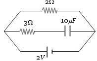
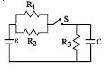
The charge on a capacitor of capacitance $10\,\mu F$ connected as shown in the figure is.......$\mu C$
A
$20$
B
$15$
C
$10$
D
$0$
Solution
(A) In a $DC$ circuit,a capacitor acts as an open circuit in the steady state.
Therefore,no current flows through the branch containing the capacitor.
The entire potential difference of the battery,which is $2\,V$,appears across the capacitor.
Using the formula for charge on a capacitor,$Q = C \times V$,where $C = 10\,\mu F$ and $V = 2\,V$.
$Q = 10\,\mu F \times 2\,V = 20\,\mu C$.
0 likes
View Solution6
MediumMCQ
$A$ parallel plate capacitor is charged to a potential difference of $50 \, V$. It is discharged through a resistance. After $1 \, s$,the potential difference between the plates becomes $40 \, V$. Then:
A
Fraction of stored energy after $1 \, s$ is $16/25$.
B
Potential difference between the plates after $2 \, s$ will be $32 \, V$.
C
Potential difference between the plates after $2 \, s$ will be $20 \, V$.
D
Both $(a)$ and $(b)$.
Solution
(D) The potential difference across a discharging capacitor is given by $V = V_0 e^{-t/CR}$.
Given $V_0 = 50 \, V$ and $V = 40 \, V$ at $t = 1 \, s$,we have $40 = 50 e^{-1/CR}$,which implies $e^{-1/CR} = 4/5$.
For option $(b)$,the potential difference after $t = 2 \, s$ is $V' = V_0 e^{-2/CR} = 50 (e^{-1/CR})^2 = 50 (4/5)^2 = 50 \times (16/25) = 32 \, V$. Thus,$(b)$ is correct.
For option $(a)$,the energy stored in a capacitor is $U = \frac{1}{2} C V^2$. The fraction of energy remaining after $1 \, s$ is $U_f / U_i = (V_f / V_i)^2 = (40/50)^2 = (4/5)^2 = 16/25$. Thus,$(a)$ is correct.
Since both $(a)$ and $(b)$ are correct,the correct option is $(d)$.
0 likes
View Solution7
MediumMCQ
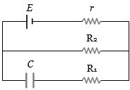
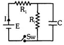
In the given figure,find the charge on the capacitor of capacitance $C$.
A
$CE$
B
$\frac{CE R_1}{R_2 - r}$
C
$\frac{CE R_2}{R_2 + r}$
D
$\frac{CE R_1}{R_1 - r}$
Solution
(C) In the steady state,the capacitor acts as an open circuit,so no current flows through the branch containing the capacitor.
Therefore,the entire current $i$ from the battery flows through the resistor $R_2$.
The total resistance of the circuit is $R_{total} = R_2 + r$.
The current in the circuit is $i = \frac{E}{R_2 + r}$.
The potential difference across the resistor $R_2$ is $V = i \times R_2 = \frac{E R_2}{R_2 + r}$.
Since the capacitor is in parallel with the resistor $R_2$,the potential difference across the capacitor is the same as the potential difference across $R_2$.
Thus,the charge on the capacitor is $Q = C \times V = \frac{C E R_2}{R_2 + r}$.
0 likes
View Solution8
DifficultMCQ
The plates of a capacitor are charged to a potential difference of $320 \, V$ and are then connected across a resistor. The potential difference across the capacitor decays exponentially with time. After $1 \, s$ the potential difference between the plates of the capacitor is $240 \, V$,then after $2 \, s$ and $3 \, s$ the potential difference between the plates will be:
A
$200 \, V$ and $180 \, V$
B
$180 \, V$ and $135 \, V$
C
$160 \, V$ and $80 \, V$
D
$140 \, V$ and $20 \, V$
Solution
(B) The potential difference across a discharging capacitor is given by $V(t) = V_0 e^{-\lambda t}$.
Given $V_0 = 320 \, V$.
After $t = 1 \, s$,$V_1 = 240 \, V$.
So,$240 = 320 e^{-\lambda} \implies e^{-\lambda} = \frac{240}{320} = \frac{3}{4}$.
After $t = 2 \, s$,the potential difference is $V_2 = V_0 (e^{-\lambda})^2 = 320 \times (\frac{3}{4})^2 = 320 \times \frac{9}{16} = 180 \, V$.
After $t = 3 \, s$,the potential difference is $V_3 = V_0 (e^{-\lambda})^3 = 320 \times (\frac{3}{4})^3 = 320 \times \frac{27}{64} = 135 \, V$.
0 likes
View Solution9
DifficultMCQ
$A$ $4 \mu F$ capacitor and a resistance of $2.5 \, M\Omega$ are in series with a $12 \, V$ battery. Find the time after which the potential difference across the capacitor is $3$ times the potential difference across the resistor. (Given $\ln(2) = 0.693$)
A
$13.86$
B
$6.93$
C
$7$
D
$14$
Solution
(A) The potential difference across the capacitor is $V_C = V_0(1 - e^{-t/RC})$ and across the resistor is $V_R = V_0 e^{-t/RC}$.
Given that $V_C = 3 V_R$,we have $V_0(1 - e^{-t/RC}) = 3 V_0 e^{-t/RC}$.
Dividing by $V_0$,we get $1 - e^{-t/RC} = 3 e^{-t/RC}$,which simplifies to $1 = 4 e^{-t/RC}$.
Thus,$e^{t/RC} = 4$,or $t/RC = \ln(4) = 2 \ln(2)$.
Given $R = 2.5 \times 10^6 \, \Omega$ and $C = 4 \times 10^{-6} \, F$,the time constant $\tau = RC = (2.5 \times 10^6) \times (4 \times 10^{-6}) = 10 \, s$.
Substituting the values,$t = 10 \times 2 \times 0.693 = 13.86 \, s$.
0 likes
View Solution10
EasyMCQ
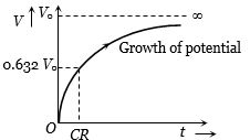
During the charging of a capacitor,the variation of the potential $V$ of the capacitor with time $t$ is shown as:
A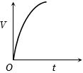
B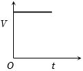
C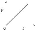
D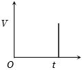
Solution
(A) During the charging of a capacitor in an $RC$ circuit,the charge $q$ on the capacitor at any time $t$ is given by $q = q_0(1 - e^{-t/CR})$.
Since the potential difference $V$ across the capacitor is $V = q/C$,we have $V = V_0(1 - e^{-t/CR})$,where $V_0$ is the maximum potential.
This equation represents an exponential growth curve that starts from $V = 0$ at $t = 0$ and asymptotically approaches $V_0$ as $t \to \infty$.
Therefore,the correct graph is the one showing exponential growth.
0 likes
View Solution11
MediumMCQ
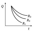
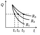
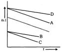
Three identical capacitors are given a charge $Q$ each and they are then allowed to discharge through resistances $R_1, R_2,$ and $R_3$. Their charges,as a function of time,are shown in the graph below. The smallest of the three resistances is
A
$R_3$
B
$R_2$
C
$R_1$
D
Cannot be predicted
Solution
(C) During the discharge of a capacitor through a resistance,the charge at any instant $t$ is given by $Q = Q_0 e^{-t/CR}$.
Rearranging the equation: $\frac{Q_0}{Q} = e^{t/CR} \implies t = CR \ln\left(\frac{Q_0}{Q}\right)$.
For a constant charge $Q$,the time $t$ is directly proportional to the resistance $R$ $(t \propto R)$.
Now,draw a line parallel to the time axis as shown in the graph. Suppose this line intersects the curves at points corresponding to times $t_1, t_2,$ and $t_3$ for resistances $R_1, R_2,$ and $R_3$ respectively.
From the graph,it is clear that $t_1 < t_2 < t_3$.
Since $t \propto R$,it follows that $R_1 < R_2 < R_3$.
Therefore,the smallest resistance is $R_1$.
0 likes
View Solution12
MediumMCQ
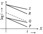
In an $RC$ circuit while charging,the graph of $\log i$ versus time is as shown by the dotted line in the diagram,where $i$ is the current. When the value of the resistance is doubled,which of the solid curves best represents the variation of $\log i$ versus time?
A
$P$
B
$Q$
C
$R$
D
$S$
Solution
(B) For an $RC$ circuit during charging,the current $i$ at time $t$ is given by $i = \frac{E}{R} e^{-t/RC}$.
Taking the natural logarithm on both sides,we get $\ln i = -\frac{t}{RC} + \ln(\frac{E}{R})$.
This is an equation of a straight line $y = mx + c$,where the slope $m = -\frac{1}{RC}$ and the intercept $c = \ln(\frac{E}{R})$.
When the resistance $R$ is doubled $(R' = 2R)$:
$1$. The intercept $c' = \ln(\frac{E}{2R}) = \ln(\frac{E}{R}) - \ln 2$. Since $\ln 2 > 0$,the new intercept $c'$ is lower than the original intercept $c$.
$2$. The magnitude of the slope $|m'| = \frac{1}{R'C} = \frac{1}{2RC} = \frac{1}{2} |m|$. The new slope is half the magnitude of the original slope,meaning the line becomes less steep.
Comparing these changes with the given graph,curve $Q$ starts at a lower intercept and has a smaller magnitude of slope compared to the dotted line. Therefore,curve $Q$ represents the variation.
0 likes
View Solution13
EasyMCQ
$A$ capacitor is connected to a cell of $emf$ $E$ having some internal resistance $r$. The potential difference across the
A
Cell is $< E$
B
Cell is $E$
C
Capacitor is $> E$
D
Capacitor is $< E$
Solution
(B) When a capacitor is connected to a cell,it charges until the potential difference across the capacitor plates becomes equal to the $emf$ of the cell.
Once the capacitor is fully charged,no current flows through the circuit $(i = 0)$.
The potential difference across the cell is given by $V = E - ir$.
Since $i = 0$,the potential difference across the cell is $V = E - 0 \times r = E$.
Therefore,the potential difference across the cell is $E$.
Once the capacitor is fully charged,no current flows through the circuit $(i = 0)$.
The potential difference across the cell is given by $V = E - ir$.
Since $i = 0$,the potential difference across the cell is $V = E - 0 \times r = E$.
Therefore,the potential difference across the cell is $E$.
0 likes
View Solution14
MediumMCQ
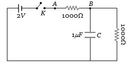
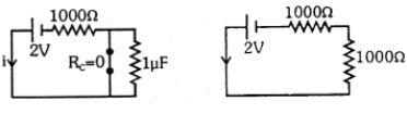
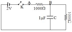
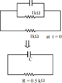
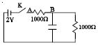
When the key $K$ is pressed at time $t = 0$, which of the following statements about the current $I$ in the resistor $AB$ of the given circuit is true?
A
$I = 2 \,mA$ at all $t$
B
$I$ oscillates between $1 \,mA$ and $2 \,mA$
C
$I = 1 \,mA$ at all $t$
D
At $t = 0$, $I = 2 \,mA$ and with time it goes to $1 \,mA$
Solution
(D) At time $t = 0$, the capacitor acts as a short circuit (zero resistance). The total resistance in the circuit is $1000 \, \Omega$. Thus, the current $I = \frac{2 \,V}{1000 \, \Omega} = 2 \,mA$.
As time passes, the capacitor charges up. When it is fully charged, it acts as an open circuit. The current then flows through the series combination of the $1000 \, \Omega$ resistor and the $1000 \, \Omega$ resistor. The total resistance becomes $2000 \, \Omega$. Thus, the steady-state current $I = \frac{2 \,V}{2000 \, \Omega} = 1 \,mA$. Therefore, the current decreases from $2 \,mA$ to $1 \,mA$ over time.
As time passes, the capacitor charges up. When it is fully charged, it acts as an open circuit. The current then flows through the series combination of the $1000 \, \Omega$ resistor and the $1000 \, \Omega$ resistor. The total resistance becomes $2000 \, \Omega$. Thus, the steady-state current $I = \frac{2 \,V}{2000 \, \Omega} = 1 \,mA$. Therefore, the current decreases from $2 \,mA$ to $1 \,mA$ over time.
0 likes
View Solution15
MediumMCQ
$A$ $4\,\mu F$ capacitor is charged to $400\,V$ and then its plates are joined through a resistance of $1\,k\Omega$. The heat produced in the resistance is ............... $J$.
A
$0.16$
B
$1.28$
C
$0.64$
D
$0.32$
Solution
(D) When a charged capacitor is discharged through a resistance,the total energy stored in the capacitor is dissipated as heat in the resistance.
Energy stored in the capacitor is given by the formula $U = \frac{1}{2}CV^2$.
Given: $C = 4\,\mu F = 4 \times 10^{-6}\,F$ and $V = 400\,V$.
Substituting the values:
$U = \frac{1}{2} \times (4 \times 10^{-6}) \times (400)^2$
$U = 2 \times 10^{-6} \times 160000$
$U = 2 \times 10^{-6} \times 1.6 \times 10^5$
$U = 3.2 \times 10^{-1} = 0.32\,J$.
Therefore,the heat produced in the resistance is $0.32\,J$.
0 likes
View Solution16
EasyMCQ
$A$ capacitor is a perfect insulator for
A
Alternating currents
B
Direct currents
C
Both $ac$ and $dc$
D
None of these
Solution
(B) The capacitive reactance of a capacitor is given by the formula $X_C = \frac{1}{\omega C} = \frac{1}{2\pi \nu C}$.
For direct current $(dc)$,the frequency $\nu = 0$.
Substituting this into the formula,we get $X_C = \frac{1}{2\pi (0) C} = \infty$.
Since the resistance (reactance) offered to $dc$ is infinite,a capacitor acts as a perfect insulator for $dc$.
For direct current $(dc)$,the frequency $\nu = 0$.
Substituting this into the formula,we get $X_C = \frac{1}{2\pi (0) C} = \infty$.
Since the resistance (reactance) offered to $dc$ is infinite,a capacitor acts as a perfect insulator for $dc$.
0 likes
View Solution17
EasyMCQ
The capacity of a pure capacitor is $1 \, F$. In $DC$ circuits,its effective resistance will be
A
Zero
B
Infinite
C
$1 \, \Omega$
D
$0.5 \, \Omega$
Solution
(B) The capacitive reactance $X_C$ is given by the formula $X_C = \frac{1}{2\pi \nu C}$,where $\nu$ is the frequency of the source and $C$ is the capacitance.
In a $DC$ circuit,the frequency $\nu = 0 \, Hz$.
Substituting this into the formula: $X_C = \frac{1}{2\pi \times 0 \times 1} = \frac{1}{0} = \infty$.
Therefore,the effective resistance (reactance) of a pure capacitor in a $DC$ circuit is infinite.
In a $DC$ circuit,the frequency $\nu = 0 \, Hz$.
Substituting this into the formula: $X_C = \frac{1}{2\pi \times 0 \times 1} = \frac{1}{0} = \infty$.
Therefore,the effective resistance (reactance) of a pure capacitor in a $DC$ circuit is infinite.
0 likes
View Solution18
DifficultMCQ
$A$ capacitor of capacitance $C$ is being discharged through a resistor $R$. Let $t_1$ be the time taken for the energy stored in the capacitor to reduce to half of its initial value,and $t_2$ be the time taken for the charge to reduce to one-fourth of its initial value. Find the ratio $t_1/t_2$.
A
$1$
B
$2$
C
$0.25$
D
$0.5$
Solution
(C) The energy stored in a capacitor is given by $U = \frac{q^2}{2C}$.
Since the charge $q$ decays as $q(t) = q_0 e^{-t/RC}$,the energy decays as $U(t) = \frac{q_0^2}{2C} e^{-2t/RC} = U_0 e^{-2t/RC}$,where $RC = \tau$ is the time constant.
For $t_1$,the energy reduces to half: $U(t_1) = U_0/2$.
$U_0/2 = U_0 e^{-2t_1/\tau} \implies 1/2 = e^{-2t_1/\tau} \implies \ln(1/2) = -2t_1/\tau \implies -\ln(2) = -2t_1/\tau \implies t_1 = \frac{\tau \ln(2)}{2}$.
For $t_2$,the charge reduces to one-fourth: $q(t_2) = q_0/4$.
$q_0/4 = q_0 e^{-t_2/\tau} \implies 1/4 = e^{-t_2/\tau} \implies \ln(1/4) = -t_2/\tau \implies -2\ln(2) = -t_2/\tau \implies t_2 = 2\tau \ln(2)$.
Taking the ratio $t_1/t_2 = \frac{\tau \ln(2) / 2}{2\tau \ln(2)} = \frac{1/2}{2} = 1/4 = 0.25$.
0 likes
View Solution19
MediumMCQ
$A$ $2500 \,\mu F$ capacitor is charged through a $1 \,k\Omega$ resistor by a $12 \,V$ d.c. source. The voltage across the capacitor after $5 \,s$ is ..... $V$.
A
$12.48$
B
$10.38$
C
$25$
D
$15.40$
Solution
(B) The time constant of the circuit is given by $\tau = RC = (1 \times 10^3 \,\Omega) \times (2500 \times 10^{-6} \,F) = 2.5 \,s$.
For a charging capacitor,the voltage at time $t$ is given by $V(t) = V_0(1 - e^{-t/\tau})$.
Substituting the given values: $V(5) = 12(1 - e^{-5/2.5}) = 12(1 - e^{-2})$.
Using $e^{-2} \approx 0.135$,we get $V(5) = 12(1 - 0.135) = 12(0.865) = 10.38 \,V$.
For a charging capacitor,the voltage at time $t$ is given by $V(t) = V_0(1 - e^{-t/\tau})$.
Substituting the given values: $V(5) = 12(1 - e^{-5/2.5}) = 12(1 - e^{-2})$.
Using $e^{-2} \approx 0.135$,we get $V(5) = 12(1 - 0.135) = 12(0.865) = 10.38 \,V$.
0 likes
View Solution20
DifficultMCQ
In an $R-C$ charging circuit,the dashed line represents the graph of $\ln I$ versus $t$. If the resistance of the circuit is doubled,which of the following solid lines represents the correct graph of $\ln I$ versus $t$?
A
$A$
B
$B$
C
$C$
D
$D$
Solution
(B) For an $R-C$ charging circuit,the current at time $t$ is given by $I = \frac{E}{R} e^{-\frac{t}{RC}}$.
Taking the natural logarithm on both sides,we get $\ln I = \ln(\frac{E}{R}) - \frac{t}{RC}$.
This is a linear equation of the form $y = mx + c$,where the slope $m = -\frac{1}{RC}$ and the intercept $c = \ln(\frac{E}{R})$.
When the resistance $R$ is doubled $(R' = 2R)$:
$1$. The new slope $m' = -\frac{1}{R'C} = -\frac{1}{2RC} = \frac{1}{2}m$. Since the slope becomes half,the line becomes less steep.
$2$. The new intercept $c' = \ln(\frac{E}{2R}) = \ln(\frac{E}{R}) - \ln 2$. Since $\ln 2 > 0$,the intercept decreases.
Comparing the options,line $B$ has a smaller (less negative) slope and a lower intercept than the dashed line,which matches the derived conditions.
0 likes
View Solution21
EasyMCQ
$A$ $2\ \mu F$ capacitor and an $R$ resistor are connected in series to a $200\ V$ $DC$ supply. $A$ neon bulb is connected across the capacitor,which glows at $120\ V$. Calculate the value of $R$ so that the bulb glows for $5\ s$ after the switch is closed. (Given: $\log_{10} 2.5 = 0.4$)
A
$2.7 \times 10^6\ \Omega$
B
$3.3 \times 10^7\ \Omega$
C
$1.3 \times 10^4\ \Omega$
D
$1.7 \times 10^5\ \Omega$
Solution
(A) The voltage across the capacitor in a charging $RC$ circuit is given by $V(t) = V_0(1 - e^{-t/RC})$.
Here,$V_0 = 200\ V$,$V(t) = 120\ V$,$t = 5\ s$,and $C = 2 \times 10^{-6}\ F$.
Substituting the values: $120 = 200(1 - e^{-5/(R \times 2 \times 10^{-6})})$.
$0.6 = 1 - e^{-5/(2 \times 10^{-6} R)} \Rightarrow e^{-5/(2 \times 10^{-6} R)} = 0.4$.
Taking natural logarithm on both sides: $-5 / (2 \times 10^{-6} R) = \ln(0.4) = \ln(2/5) = -\ln(2.5)$.
Since $\ln(2.5) = 2.303 \times \log_{10}(2.5) = 2.303 \times 0.4 = 0.9212$.
$5 / (2 \times 10^{-6} R) = 0.9212$.
$R = 5 / (2 \times 10^{-6} \times 0.9212) \approx 2.71 \times 10^6\ \Omega$.
0 likes
View Solution22
MediumMCQ
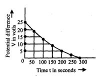
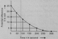
The figure shows an experimental graph of the discharging of a capacitor in an $RC$ circuit. The time constant of this circuit lies between which of the following time intervals?
A
$100 \ s$ and $150 \ s$
B
$150 \ s$ and $200 \ s$
C
$0 \ s$ and $50 \ s$
D
$50 \ s$ and $100 \ s$
Solution
(A) The potential difference across a discharging capacitor is given by $V(t) = V_0 e^{-t/\tau}$,where $\tau$ is the time constant.
At $t = \tau$,the potential difference is $V(\tau) = V_0 e^{-1} \approx 0.37 V_0$.
From the graph,the initial potential difference $V_0 = 25 \ V$.
Therefore,at $t = \tau$,$V(\tau) = 0.37 \times 25 \ V = 9.25 \ V$.
Looking at the graph,at $t = 100 \ s$,$V \approx 13 \ V$ and at $t = 150 \ s$,$V \approx 9 \ V$.
Since $9.25 \ V$ lies between $13 \ V$ and $9 \ V$,the time constant $\tau$ must lie between $100 \ s$ and $150 \ s$.
0 likes
View Solution23
MediumMCQ
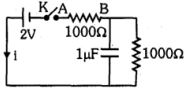
At time $t = 0$,the switch $K$ is closed. Which of the following statements is true for the current '$i$' flowing through the resistor $AB$ in the given circuit?
A
At $t = 0$,$i = 2 \ mA$ and it decreases to $1 \ mA$ as time passes.
B
The current $i$ oscillates between $1 \ mA$ and $2 \ mA$.
C
At all times $t$,$i = 2 \ mA$.
D
At all times $t$,$i = 1 \ mA$.
Solution
(A) At $t = 0$,the capacitor acts as a short circuit (resistance $R_C = 0$). The circuit consists of the $2 \ V$ battery and the $1000 \ \Omega$ resistor in series with the shorted capacitor branch. Thus,the current $i$ is given by $i = \frac{V}{R} = \frac{2 \ V}{1000 \ \Omega} = 2 \ mA$.
As $t \to \infty$,the capacitor becomes fully charged and acts as an open circuit (resistance $R_C = \infty$). The current now flows through both $1000 \ \Omega$ resistors in series. The total resistance is $R_{total} = 1000 \ \Omega + 1000 \ \Omega = 2000 \ \Omega$. Thus,the steady-state current is $i = \frac{V}{R_{total}} = \frac{2 \ V}{2000 \ \Omega} = 1 \ mA$.
Therefore,at $t = 0$,$i = 2 \ mA$,and as time passes,the current decreases exponentially to $1 \ mA$.
0 likes
View Solution24
DifficultMCQ
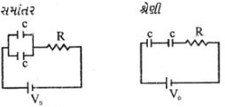
In an experiment with a $C-R$ circuit,two identical capacitors,a resistor,and a $6V$ voltage source are used. For the parallel combination of capacitors,the time required for the voltage to reach half of its fully charged value is $10 \ s$. For the series combination,the time required for the voltage to reach half of its fully charged value is ...... $s$.
A
$20$
B
$10$
C
$5$
D
$2.5$
Solution
(D) The charging voltage of a capacitor in an $RC$ circuit is given by $V(t) = V_0(1 - e^{-t/RC_{eq}})$.
For parallel combination,equivalent capacitance $C_p = C + C = 2C$. The time constant is $\tau_p = R(2C) = 2RC$.
Given $V(t_p) = V_0/2$ at $t_p = 10 \ s$,we have $V_0/2 = V_0(1 - e^{-t_p/2RC})$,which implies $1/2 = e^{-t_p/2RC}$,so $t_p = 2RC \ln(2) = 10 \ s$.
For series combination,equivalent capacitance $C_s = C/2$. The time constant is $\tau_s = R(C/2) = RC/2$.
We need to find $t_s$ such that $V(t_s) = V_0/2$,so $1/2 = e^{-t_s/(RC/2)}$,which implies $t_s = (RC/2) \ln(2)$.
Comparing the two expressions,$t_s = t_p / 4 = 10 / 4 = 2.5 \ s$.
0 likes
View Solution25
DifficultMCQ
$A$ capacitor is charged to a potential difference of $100\, V$ and then connected across a resistor. The potential difference across the capacitor decays exponentially with time. After $1\, s$,the potential difference across the capacitor plates is $80\, V$. What is the fractional loss of the stored energy?
A
$11/9$
B
$12/25$
C
$25/9$
D
$9/25$
Solution
(D) The energy stored in a capacitor is given by $U = \frac{1}{2}CV^2$.
Initial energy $U_0 = \frac{1}{2}CV_0^2$,where $V_0 = 100\, V$.
Final energy $U = \frac{1}{2}CV^2$,where $V = 80\, V$.
The energy lost is $\Delta U = U_0 - U = \frac{1}{2}CV_0^2 - \frac{1}{2}CV^2$.
The fractional loss of energy is $\frac{\Delta U}{U_0} = \frac{\frac{1}{2}CV_0^2 - \frac{1}{2}CV^2}{\frac{1}{2}CV_0^2} = \frac{V_0^2 - V^2}{V_0^2}$.
Substituting the values: $\frac{\Delta U}{U_0} = \frac{100^2 - 80^2}{100^2} = \frac{(100 - 80)(100 + 80)}{10000} = \frac{20 \times 180}{10000} = \frac{3600}{10000} = \frac{36}{100} = \frac{9}{25}$.
0 likes
View Solution26
DifficultMCQ
Let $C$ be the capacitance of a capacitor discharging through a resistor $R$. Suppose $t_{1}$ is the time taken for the energy stored in the capacitor to reduce to half its initial value and $t_{2}$ is the time taken for the charge to reduce to one-fourth its initial value. Then the ratio $t_{1} / t_{2}$ will be
A
$2$
B
$1$
C
$0.5$
D
$0.25$
Solution
(D) The energy stored in a capacitor is given by $U = \frac{q^2}{2C}$.
For energy to reduce to half its initial value: $\frac{U_0}{2} = \frac{q^2}{2C} \Rightarrow \frac{q_0^2}{2} = q^2 \Rightarrow q = \frac{q_0}{\sqrt{2}}$.
Using the discharging equation $q = q_0 e^{-t/RC}$,we have $\frac{q_0}{\sqrt{2}} = q_0 e^{-t_1/RC}$.
Taking the natural logarithm: $-\frac{t_1}{RC} = \ln(1/\sqrt{2}) = -\frac{1}{2} \ln 2$,so $t_1 = \frac{RC \ln 2}{2}$.
For charge to reduce to one-fourth its initial value: $\frac{q_0}{4} = q_0 e^{-t_2/RC}$.
Taking the natural logarithm: $-\frac{t_2}{RC} = \ln(1/4) = -2 \ln 2$,so $t_2 = 2RC \ln 2$.
The ratio $\frac{t_1}{t_2} = \frac{(RC \ln 2) / 2}{2RC \ln 2} = \frac{1}{4} = 0.25$.
0 likes
View Solution27
MediumMCQ
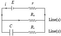
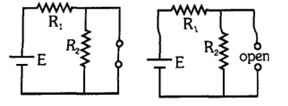
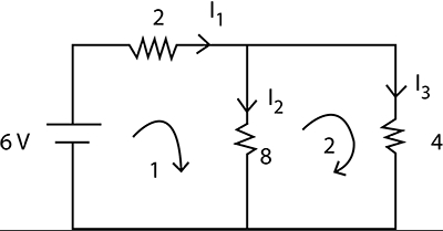
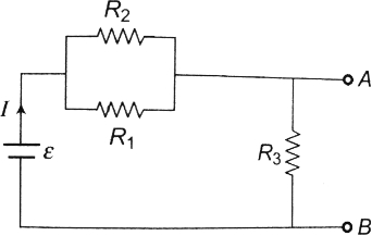
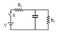
Find the current from the battery at $(i)$ $t \rightarrow 0$ (initial) and $(ii)$ $t \rightarrow \infty$ (after a long time) when the switch is closed at $t = 0$.
A
$I = \frac{E}{R_1}, I = \frac{E}{R_1 - R_2}$
B
$I = \frac{E}{R_1}, I = \frac{E}{R_1 + R_2}$
C
$I = \frac{E}{R_2}, I = \frac{E}{R_1}$
D
$I = \frac{R_1 + R_2}{E + R_1}, I = \frac{E}{R_1 + R_2}$
Solution
(B) $(i)$ At $t \rightarrow 0$,the capacitor acts as a short circuit (zero resistance wire). In this state,the total resistance of the circuit is $R_1$. Therefore,the current $I = \frac{E}{R_1}$.
$(ii)$ At $t \rightarrow \infty$,the capacitor is fully charged and acts as an open circuit (no current flows through it). In this state,the resistors $R_1$ and $R_2$ are in series. The total resistance is $R_1 + R_2$. Therefore,the current $I = \frac{E}{R_1 + R_2}$.
$(ii)$ At $t \rightarrow \infty$,the capacitor is fully charged and acts as an open circuit (no current flows through it). In this state,the resistors $R_1$ and $R_2$ are in series. The total resistance is $R_1 + R_2$. Therefore,the current $I = \frac{E}{R_1 + R_2}$.
0 likes
View Solution28
DifficultMCQ
When the switch $K$ is closed at $t = 0$,what can be said about the current passing through the resistor $AB$ in the given circuit?
A
For any $t$,$I = 2\,mA$
B
$I$ oscillates between $1\,mA$ and $2\,mA$
C
At $t = 0$,$I = 2\,mA$ and as time passes,it becomes $1\,mA$
D
At $t = 0$,$I = 1\,mA$ and as time passes,it becomes $2\,mA$
Solution
(C) At $t = 0$,the capacitor acts as a short circuit (uncharged). The total resistance in the circuit is $1000\,\Omega$. Thus,the current $I = \frac{V}{R} = \frac{2\,V}{1000\,\Omega} = 2\,mA$.
As $t \to \infty$,the capacitor becomes fully charged and acts as an open circuit. The current now flows through the series combination of the two $1000\,\Omega$ resistors. The total resistance is $1000\,\Omega + 1000\,\Omega = 2000\,\Omega$. Thus,the current $I = \frac{V}{R_{total}} = \frac{2\,V}{2000\,\Omega} = 1\,mA$.
As $t \to \infty$,the capacitor becomes fully charged and acts as an open circuit. The current now flows through the series combination of the two $1000\,\Omega$ resistors. The total resistance is $1000\,\Omega + 1000\,\Omega = 2000\,\Omega$. Thus,the current $I = \frac{V}{R_{total}} = \frac{2\,V}{2000\,\Omega} = 1\,mA$.
0 likes
View Solution29
MediumMCQ
$A$ capacitor is charged to $320\ V$ and then connected to a resistor. After $1\ s$,the voltage is $240\ V$. What will be the voltage after $2\ s$ and $3\ s$?
A
$200\ V$ and $180\ V$
B
$180\ V$ and $135\ V$
C
$160\ V$ and $80\ V$
D
$140\ V$ and $20\ V$
Solution
(B) The voltage across a discharging capacitor is given by $V(t) = V_0 e^{-t/RC}$.
Let $k = e^{-1/RC}$. Given $V_0 = 320\ V$ and $V(1) = 240\ V$.
$240 = 320 \cdot k \implies k = \frac{240}{320} = \frac{3}{4}$.
For $t = 2\ s$,$V(2) = V_0 \cdot k^2 = 320 \cdot (\frac{3}{4})^2 = 320 \cdot \frac{9}{16} = 180\ V$.
For $t = 3\ s$,$V(3) = V_0 \cdot k^3 = 320 \cdot (\frac{3}{4})^3 = 320 \cdot \frac{27}{64} = 135\ V$.
0 likes
View Solution30
DifficultMCQ
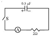
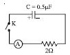
$A$ charged capacitor is allowed to discharge through a resistance of $2 \, \Omega$ by closing the switch $S$ at the instant $t = 0$. At time $t = \ln 2 \, \mu s$,the reading of the ammeter falls to half of its initial value. The resistance of the ammeter is equal to:
A
$0 \, \Omega$
B
$2 \, \Omega$
C
$\infty \, \Omega$
D
$2 \, M\Omega$
Solution
(A) The current in a discharging $RC$ circuit is given by $I(t) = I_0 e^{-t/\tau}$,where $\tau = R_{eq}C$ is the time constant.
Here,$R_{eq} = R + r$,where $R = 2 \, \Omega$ is the external resistance and $r$ is the resistance of the ammeter.
The capacitance is $C = 0.5 \, \mu F = 0.5 \times 10^{-6} \, F$.
Given that at $t = \ln 2 \, \mu s = \ln 2 \times 10^{-6} \, s$,the current $I(t) = I_0 / 2$.
Substituting these values into the equation: $I_0 / 2 = I_0 e^{-t/\tau} \Rightarrow 1/2 = e^{-t/\tau}$.
Taking the natural logarithm on both sides: $\ln(1/2) = -t/\tau \Rightarrow -\ln 2 = -t/\tau \Rightarrow \tau = t / \ln 2$.
Substituting $t = \ln 2 \, \mu s$: $\tau = (\ln 2 \, \mu s) / \ln 2 = 1 \, \mu s = 10^{-6} \, s$.
Since $\tau = (R + r)C$,we have $10^{-6} = (2 + r) \times 0.5 \times 10^{-6}$.
Dividing both sides by $10^{-6}$: $1 = (2 + r) \times 0.5$.
$2 = 2 + r \Rightarrow r = 0 \, \Omega$.
0 likes
View Solution31
DifficultMCQ
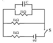
$A$ capacitor $C = 100 \, \mu F$ is connected to three resistors,each of resistance $1 \, k\Omega$,and a battery of $emf$ $9 \, V$. The switch $S$ has been closed for a long time to charge the capacitor. When switch $S$ is opened,the capacitor discharges with a time constant of ...... $ms$.
A
$33$
B
$5$
C
$3.3$
D
$50$
Solution
(D) When the switch $S$ is opened,the battery and the resistor in series with it are removed from the circuit. The capacitor $C$ is left in a loop with two resistors of $1 \, k\Omega$ each,which are connected in parallel to each other.
The equivalent resistance $R_{eq}$ of these two resistors in parallel is given by:
$R_{eq} = \frac{1 \, k\Omega \times 1 \, k\Omega}{1 \, k\Omega + 1 \, k\Omega} = 0.5 \, k\Omega = 500 \, \Omega$.
The time constant $\tau$ for the discharging circuit is given by:
$\tau = R_{eq} C$
$\tau = (500 \, \Omega) \times (100 \times 10^{-6} \, F)$
$\tau = 50000 \times 10^{-6} \, s = 0.05 \, s$
Converting the time constant to milliseconds $(ms)$:
$\tau = 0.05 \times 1000 \, ms = 50 \, ms$.
0 likes
View Solution32
AdvancedMCQ
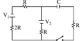
In the transient circuit shown,the time constant of the circuit is:
A
$\frac{5}{3} RC$
B
$\frac{5}{2} RC$
C
$\frac{7}{4} RC$
D
$\frac{7}{3} RC$
Solution
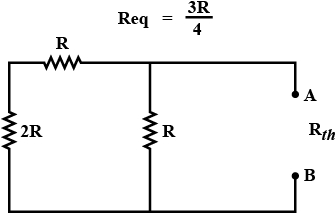
(C) To find the time constant $\tau = R_{eq}C$,we need to determine the equivalent resistance $R_{eq}$ as seen by the capacitor $C$ when the voltage sources are short-circuited.
$1$. Short-circuit the voltage sources $V_1$ and $V_2$. The resistor $2R$ and $R$ (in the left branch) are in series,giving $3R$.
$2$. This $3R$ is in parallel with the middle resistor $R$. The equivalent resistance of this part is $R_{th} = \frac{(3R \times R)}{(3R + R)} = \frac{3R^2}{4R} = \frac{3}{4}R$.
$3$. The capacitor $C$ is in series with the resistor $R$ on the right side. Thus,the total equivalent resistance $R_{eq}$ seen by the capacitor is $R_{eq} = R_{th} + R = \frac{3}{4}R + R = \frac{7}{4}R$.
$4$. Therefore,the time constant is $\tau = R_{eq}C = \frac{7}{4}RC$.
0 likes
View Solution33
DifficultMCQ
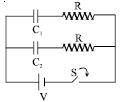
In the circuit shown in the figure,$C_1 = 2C_2$. Switch $S$ is closed at time $t = 0$. Let $i_1$ and $i_2$ be the currents flowing through the branches containing $C_1$ and $C_2$ respectively at any time $t$. Then the ratio $i_1 / i_2$:
A
is constant
B
increases with increase in time $t$
C
decreases with increase in time $t$
D
first increases then decreases
Solution
(B) The circuit consists of two $RC$ branches connected in parallel to a voltage source $V$. When the switch $S$ is closed at $t = 0$,each branch charges independently.
For the first branch with capacitor $C_1$ and resistor $R$,the current is given by $i_1(t) = \frac{V}{R} e^{-t / (R C_1)}$.
For the second branch with capacitor $C_2$ and resistor $R$,the current is given by $i_2(t) = \frac{V}{R} e^{-t / (R C_2)}$.
The ratio of the currents is $\frac{i_1}{i_2} = \frac{\frac{V}{R} e^{-t / (R C_1)}}{\frac{V}{R} e^{-t / (R C_2)}} = e^{-t / (R C_1) + t / (R C_2)} = e^{\frac{t}{R} \left( \frac{1}{C_2} - \frac{1}{C_1} \right)}$.
Given $C_1 = 2C_2$,we have $\frac{1}{C_2} = \frac{2}{C_1}$.
Substituting this into the ratio: $\frac{i_1}{i_2} = e^{\frac{t}{R} \left( \frac{2}{C_1} - \frac{1}{C_1} \right)} = e^{\frac{t}{R C_1}}$.
Since $t$ increases,the exponent $\frac{t}{R C_1}$ increases,and therefore the ratio $i_1 / i_2 = e^{\frac{t}{R C_1}}$ increases with time $t$.
0 likes
View Solution34
DifficultMCQ
In the circuit shown,when the key $K$ is pressed at time $t = 0$,which of the following statements about current $I$ in the resistor $AB$ is true?
A
$I = 2\,mA$ at all $t$
B
$I$ oscillates between $1\,mA$ and $2\,mA$
C
$I = 1\,mA$ at all $t$
D
At $t = 0$,$I = 2\,mA$ and with time it decreases to $1\,mA$
Solution
(D) At $t = 0$,the capacitor acts as a short circuit (it is uncharged). The total resistance in the circuit is $1000\,\Omega$. Thus,the current $I$ through the resistor $AB$ is $I = \frac{2\,V}{1000\,\Omega} = 2\,mA$.
As time passes,the capacitor charges. As it charges,its potential difference increases,which opposes the flow of current.
After a long time $(t \to \infty)$,the capacitor is fully charged and acts as an open circuit. The current then flows through both resistors in series. The total resistance becomes $1000\,\Omega + 1000\,\Omega = 2000\,\Omega$. The current $I$ through the resistor $AB$ becomes $I = \frac{2\,V}{2000\,\Omega} = 1\,mA$.
Therefore,at $t = 0$,$I = 2\,mA$,and as $t$ increases,$I$ decreases to $1\,mA$.
0 likes
View Solution35
MediumMCQ
In the $R-C$ circuit shown in the figure, the total energy of $3.6 \times 10^{-3} \ J$ is dissipated in the $10 \ \Omega$ resistor when the switch $S$ is closed. The initial charge on the capacitor is ..... $\mu C$.

A
$60$
B
$120$
C
$60 \sqrt{2}$
D
$\frac{60}{\sqrt{2}}$
Solution
(B) When the switch $S$ is closed, the energy stored in the capacitor is completely dissipated as heat through the resistor.
The energy stored in a capacitor with capacitance $C$ and initial charge $Q$ is given by $U = \frac{Q^2}{2C}$.
Given, $U = 3.6 \times 10^{-3} \ J$ and $C = 2 \ \mu F = 2 \times 10^{-6} \ F$.
Equating the energy, we have:
$\frac{Q^2}{2 \times 2 \times 10^{-6}} = 3.6 \times 10^{-3}$
$Q^2 = 3.6 \times 10^{-3} \times 4 \times 10^{-6}$
$Q^2 = 14.4 \times 10^{-9} = 144 \times 10^{-10}$
Taking the square root on both sides:
$Q = \sqrt{144 \times 10^{-10}} = 12 \times 10^{-5} \ C$
Converting to microcoulombs $(\mu C)$:
$Q = 120 \times 10^{-6} \ C = 120 \ \mu C$.
0 likes
View Solution36
AdvancedMCQ
$A$ charged capacitor is allowed to discharge through a resistor by closing the key at the instant $t = 0$. At the instant $t = (\ln 4) \, \mu s$,the reading of the ammeter falls to half the initial value. The resistance of the ammeter is equal to
A
$1 \, M\Omega$
B
$1 \, \Omega$
C
$2 \, \Omega$
D
$2 \, M\Omega$
Solution
(C) During discharging,the current in the circuit is given by $i(t) = i_0 e^{-t / RC}$.
Given that at $t = (\ln 4) \, \mu s$,the current $i = i_0 / 2$.
Substituting these values into the equation: $i_0 / 2 = i_0 e^{-(\ln 4 \, \mu s) / RC}$.
This simplifies to $1/2 = e^{-(\ln 4 \, \mu s) / RC}$,or $2 = e^{(\ln 4 \, \mu s) / RC}$.
Taking the natural logarithm on both sides: $\ln 2 = (\ln 4 \, \mu s) / RC$.
Since $\ln 4 = 2 \ln 2$,we have $\ln 2 = (2 \ln 2 \, \mu s) / RC$.
Thus,$RC = 2 \, \mu s$.
Given $C = 0.5 \, \mu F$,we find $R = (2 \, \mu s) / (0.5 \, \mu F) = 4 \, \Omega$.
The total resistance $R$ is the sum of the resistor and the ammeter resistance $r$: $R = 2 \, \Omega + r$.
Therefore,$2 \, \Omega + r = 4 \, \Omega$,which gives $r = 2 \, \Omega$.
0 likes
View Solution37
AdvancedMCQ
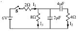
In the circuit shown in the figure,the switch $S$ is initially open and the capacitor is initially uncharged. $I_1, I_2$ and $I_3$ represent the current in the resistance $2\,\Omega, 8\,\Omega$ and $4\,\Omega$ respectively.
A
Just after the switch $S$ is closed,$I_1 = 3\,A, I_2 = 0$ and $I_3 = 0$.
B
Just after the switch $S$ is closed,$I_1 = 3\,A, I_2 = 0$ and $I_3 = 0$.
C
Long time after the switch $S$ is closed,$I_1 = 0.6\,A, I_2 = 0$ and $I_3 = 0$.
D
Long after the switch $S$ is closed,$I_1 = I_2 = I_3 = 0.6\,A$.
Solution
(C) Just after the switch $S$ is closed,the capacitors act as short circuits (wires) because they are initially uncharged. However,looking at the circuit,the capacitors are in series with the $4\,\Omega$ resistor and in parallel with the $8\,\Omega$ resistor. At $t=0$,the capacitor acts as a wire,so the $4\,\Omega$ branch is effectively shorted. The circuit simplifies to the $6\,V$ battery in series with the $2\,\Omega$ resistor and the $8\,\Omega$ resistor. Thus,$I_1 = I_3 = 6\,V / (2\,\Omega + 8\,\Omega) = 0.6\,A$ and $I_2 = 0$.
Long time after the switch $S$ is closed,the capacitors are fully charged and act as open circuits. The branch containing the $4\,\Omega$ resistor and the capacitor will have no current $(I_2 = 0)$. The circuit simplifies to the $6\,V$ battery in series with the $2\,\Omega$ and $8\,\Omega$ resistors. Thus,$I_1 = I_3 = 6\,V / (10\,\Omega) = 0.6\,A$ and $I_2 = 0$.
Long time after the switch $S$ is closed,the capacitors are fully charged and act as open circuits. The branch containing the $4\,\Omega$ resistor and the capacitor will have no current $(I_2 = 0)$. The circuit simplifies to the $6\,V$ battery in series with the $2\,\Omega$ and $8\,\Omega$ resistors. Thus,$I_1 = I_3 = 6\,V / (10\,\Omega) = 0.6\,A$ and $I_2 = 0$.
0 likes
View Solution38
DifficultMCQ
The circuit shown in the figure consists of a battery of $emf$ $\varepsilon = 10 \,V$,a capacitor of capacitance $C = 1.0 \, \mu F$,and three resistors of values $R_1 = 2 \, \Omega$,$R_2 = 2 \, \Omega$,and $R_3 = 1 \, \Omega$. Initially,the capacitor is completely uncharged and the switch $S$ is open. The switch $S$ is closed at $t = 0$.
A
The current through resistor $R_3$ at the moment the switch is closed is $5 \, A$.
B
The current through resistor $R_3$ a long time after the switch is closed is $2.5 \, A$.
C
The ratio of current through $R_1$ and $R_2$ is always constant.
D
All of the above.
Solution
(D) At $t = 0$,the capacitor acts as a short circuit. The equivalent resistance of the circuit is $R_{eq} = R_3 + (R_1 || R_2) = 1 + \frac{2 \times 2}{2 + 2} = 1 + 1 = 2 \, \Omega$. The total current from the battery is $I = \frac{\varepsilon}{R_{eq}} = \frac{10}{2} = 5 \, A$. This current flows through $R_3$,so option $A$ is correct.
As $t \to \infty$,the capacitor is fully charged and acts as an open circuit. The current flows through the series combination of $R_1 || R_2$ and $R_3$. The total resistance is $R_{eq} = 2 \, \Omega$. The current through $R_3$ is $I = \frac{10}{2} = 5 \, A$. Note: The original option $B$ was incorrect; the current is $5 \, A$ at $t \to \infty$ as well.
Since $R_1$ and $R_2$ are in parallel,the voltage across them is the same. Thus,$I_{R_1} R_1 = I_{R_2} R_2$,which implies $\frac{I_{R_1}}{I_{R_2}} = \frac{R_2}{R_1} = \frac{2}{2} = 1$. This ratio is constant. Thus,option $C$ is correct.
Given the options,$D$ is the most appropriate choice as $A$ and $C$ are correct.
0 likes
View Solution39
DifficultMCQ
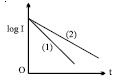
$A$ capacitor of capacity $C$ is charged to a steady potential difference $V$ and connected in series with an open key and a pure resistor $R$. At time $t = 0$,the key is closed. If $I$ is the current at time $t$,a plot of $\log I$ against $t$ is as shown in $(1)$ in the graph. Later,one of the parameters,i.e.,$V, R,$ or $C$,is changed while keeping the other two constant,and the graph $(2)$ is recorded. Then:
A
$C$ is reduced
B
$C$ is increased
C
$R$ is reduced
D
$R$ is increased
Solution
(B) The circuit represents the discharging of a capacitor through a resistor $R$. The current $I$ at time $t$ is given by $I = I_0 e^{-t / RC}$,where $I_0 = V/R$.
Taking the natural logarithm on both sides: $\ln I = \ln(V/R) - \frac{t}{RC}$.
Converting to base $10$ logarithm: $\log_{10} I = \log_{10}(V/R) - \frac{t}{2.303 RC}$.
Comparing this with the equation of a straight line $y = mx + c$,the intercept is $\log_{10}(V/R)$ and the slope is $m = -\frac{1}{2.303 RC}$.
From the graph,the intercept for both lines $(1)$ and $(2)$ is the same,which implies that $V$ and $R$ remain constant.
The magnitude of the slope of line $(2)$ is less than that of line $(1)$.
Since $|m| = \frac{1}{2.303 RC}$,a decrease in the magnitude of the slope implies that the product $RC$ must increase.
Since $R$ is constant,$C$ must be increased.
0 likes
View Solution40
DifficultMCQ
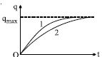
The charge across the capacitor in two different $RC$ circuits $1$ and $2$ are plotted as shown in the figure. Choose the correct statement$(s)$ related to the two circuits.
A
Both the capacitors are charged to the same charge.
B
The $emf's$ of cells in both the circuits are equal.
C
The $emf's$ of the cells may be different.
D
$A$ and $C$ both
Solution
(D) From the graph,both circuits reach the same maximum charge $q_{\max}$.
Since $q_{\max} = C_1 V_1 = C_2 V_2$,it is clear that both capacitors are charged to the same magnitude of charge. Thus,statement $A$ is correct.
The time constant $\tau = RC$ determines the rate of charging. From the graph,circuit $2$ takes more time to reach $q_{\max}$ compared to circuit $1$,implying $\tau_2 > \tau_1$,or $R_2 C_2 > R_1 C_1$.
Since $q_{\max} = CV$,we have $V = q_{\max} / C$. Because we do not know the individual values of $C_1$ and $C_2$,we cannot determine the relationship between $V_1$ and $V_2$. Therefore,the $emf's$ ($V_1$ and $V_2$) may be different. Thus,statement $C$ is also correct.
Since both $A$ and $C$ are correct,the correct option is $D$.
0 likes
View Solution41
MediumMCQ
The charge across the capacitor in two different $RC$ circuits $1$ and $2$ are plotted as shown in the figure. Identify the correct statement$(s)$ related to the $R_1, R_2, C_1$ and $C_2$ of the two $RC$ circuits.
A
$R_1 > R_2$ if $E_1 = E_2$
B
$C_1 < C_2$ if $E_1 = E_2$
C
$R_1C_1 > R_2C_2$
D
$\frac{R_1}{R_2} < \frac{C_2}{C_1}$
Solution
(D) The charge on a capacitor during charging is given by $q(t) = CE(1 - e^{-t/RC})$.
The time constant is $\tau = RC$.
From the graph,circuit $2$ takes more time to reach the maximum charge compared to circuit $1$,which means the time constant of circuit $2$ is greater than that of circuit $1$.
Thus,$\tau_2 > \tau_1$,which implies $R_2C_2 > R_1C_1$.
Rearranging this,we get $\frac{R_1}{R_2} < \frac{C_2}{C_1}$.
Therefore,option $D$ is correct.
0 likes
View Solution42
MediumMCQ
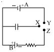
In the circuit shown,the cells are ideal and of equal emfs $E$. The capacitance of the capacitor is $C$ and the resistance of the resistor is $R$. $X$ is first joined to $Y$ and then to $Z$. After a long time,the total heat produced in the resistor will be:
A
equal to the energy finally stored in the capacitor
B
half of the energy finally stored in the capacitor
C
twice the energy finally stored in the capacitor
D
$4$ times the energy finally stored in the capacitor
Solution
(D) $1$. When $X$ is connected to $Y$,the capacitor charges to a potential difference $V = E$. The charge on the capacitor is $q_1 = CE$. The energy stored is $U_1 = \frac{1}{2}CE^2$.
$2$. When $X$ is connected to $Z$,the capacitor is connected to cell $B$ with reversed polarity. The potential difference across the capacitor changes from $+E$ to $-E$. The final charge on the capacitor is $q_2 = -CE$.
$3$. The total charge that flows through the circuit is $\Delta q = q_1 - q_2 = CE - (-CE) = 2CE$.
$4$. The work done by the cell $B$ is $W = \Delta q \cdot E = (2CE) \cdot E = 2CE^2$.
$5$. The change in energy stored in the capacitor is $\Delta U = U_f - U_i = \frac{1}{2}CE^2 - \frac{1}{2}CE^2 = 0$.
$6$. By the work-energy theorem,$W = \Delta U + H$,where $H$ is the heat produced. Thus,$H = W = 2CE^2$.
$7$. Since the final energy stored is $U_f = \frac{1}{2}CE^2$,we have $H = 4 \cdot (\frac{1}{2}CE^2) = 4U_f$. Therefore,the heat produced is $4$ times the energy finally stored in the capacitor.
0 likes
View Solution43
DifficultMCQ
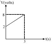
$A$ circuit element is placed in a closed box. At time $t=0$,a constant current generator supplying a current of $1\, A$ is connected across the box. The potential difference across the box varies according to the graph shown in the figure. The element in the box is:
A
resistance of $2\, \Omega$
B
battery of $emf\, 6\, V$
C
inductance of $2\, H$
D
capacitance of $0.5\, F$
Solution
(D) From the graph,the potential difference $V$ as a function of time $t$ is a linear equation: $V(t) = mt + c$.
At $t=0$,$V=2\, V$,so the intercept $c=2$.
At $t=3\, s$,$V=8\, V$,so the slope $m = \frac{8-2}{3-0} = \frac{6}{3} = 2\, V/s$.
Thus,$V(t) = 2t + 2$.
For a capacitor,$V = \frac{q}{C} = \frac{1}{C} \int i \, dt$.
Given $i = 1\, A$,we have $V = \frac{1}{C} \int 1 \, dt = \frac{t}{C} + V_0$,where $V_0$ is the initial voltage at $t=0$.
Comparing $V(t) = \frac{1}{C}t + 2$ with $V(t) = 2t + 2$,we get $\frac{1}{C} = 2$,which implies $C = 0.5\, F$.
0 likes
View Solution44
MediumMCQ
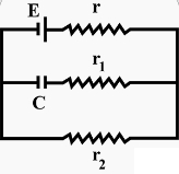
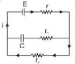
In the given circuit diagram,when the current reaches a steady state,the charge on the capacitor of capacitance $C$ will be:
A
$CE$
B
$CE \frac{r_1}{r_1 + r_2}$
C
$CE \frac{r_2}{r + r_2}$
D
$CE \frac{r_1}{r_1 + r}$
Solution
(C) In the steady state,the capacitor acts as an open circuit,so no current flows through the branch containing the capacitor $C$ and resistor $r_1$.
The circuit reduces to a simple series circuit consisting of the battery $E$ and resistors $r$ and $r_2$.
The current $i$ flowing through the circuit is given by:
$i = \frac{E}{r + r_2}$
The potential difference across the capacitor $V_c$ is equal to the potential difference across the resistor $r_2$ because they are connected in parallel.
$V_c = i \cdot r_2 = \left( \frac{E}{r + r_2} \right) r_2$
The charge $Q$ on the capacitor is given by $Q = C V_c$.
Substituting the value of $V_c$:
$Q = C \left( \frac{E r_2}{r + r_2} \right) = CE \frac{r_2}{r + r_2}$
0 likes
View Solution45
DifficultMCQ
$A$ capacitor of capacitance $C$ is discharging through a resistor $R$. Let $t_1$ be the time taken for the energy stored in the capacitor to reduce to half of its initial value,and $t_2$ be the time taken for the charge to reduce to one-fourth of its initial value. Then the ratio $t_1 / t_2$ is:
A
$2$
B
$1$
C
$0.5$
D
$0.25$
Solution
(D) The charge on a discharging capacitor is given by $q(t) = q_0 e^{-t/RC}$.
The energy stored in the capacitor is $U(t) = \frac{q^2}{2C} = \frac{q_0^2}{2C} e^{-2t/RC} = U_0 e^{-2t/RC}$.
For time $t_1$,the energy reduces to half: $U_0/2 = U_0 e^{-2t_1/RC} \implies 1/2 = e^{-2t_1/RC} \implies \ln(2) = 2t_1/RC \implies t_1 = \frac{RC \ln(2)}{2}$.
For time $t_2$,the charge reduces to one-fourth: $q_0/4 = q_0 e^{-t_2/RC} \implies 1/4 = e^{-t_2/RC} \implies \ln(4) = t_2/RC \implies t_2 = RC \ln(4) = 2RC \ln(2)$.
The ratio $t_1 / t_2 = \frac{RC \ln(2) / 2}{2RC \ln(2)} = 1/4 = 0.25$.
0 likes
View Solution46
MediumMCQ
$A$ resistor $R$ and a $2 \ \mu F$ capacitor in series are connected through a switch to a $200 \ V$ direct supply. Across the capacitor is a neon bulb that lights up at $120 \ V$. Calculate the value of $R$ to make the bulb light up $5 \ s$ after the switch has been closed. (Given: $\log_{10} 2.5 = 0.4$)
A
$1.7 \times 10^5 \ \Omega$
B
$2.7 \times 10^6 \ \Omega$
C
$3.3 \times 10^7 \ \Omega$
D
$1.3 \times 10^4 \ \Omega$
Solution
(B) The voltage across a charging capacitor in an $RC$ circuit is given by $V(t) = V_0(1 - e^{-t/RC})$.
Here,$V_0 = 200 \ V$,$V(t) = 120 \ V$,$C = 2 \times 10^{-6} \ F$,and $t = 5 \ s$.
Substituting the values: $120 = 200(1 - e^{-5/(R \times 2 \times 10^{-6})})$.
$0.6 = 1 - e^{-5/(R \times 2 \times 10^{-6})} \Rightarrow e^{-5/(R \times 2 \times 10^{-6})} = 0.4$.
Taking the natural logarithm on both sides: $-5/(R \times 2 \times 10^{-6}) = \ln(0.4) = -\ln(2.5)$.
$5/(R \times 2 \times 10^{-6}) = \ln(2.5) = 2.303 \times \log_{10}(2.5)$.
Given $\log_{10}(2.5) = 0.4$,so $\ln(2.5) = 2.303 \times 0.4 = 0.9212$.
$R = 5 / (2 \times 10^{-6} \times 0.9212) \approx 2.71 \times 10^6 \ \Omega$.
0 likes
View Solution47
MediumMCQ
The figure shows an experimental plot for discharging of a capacitor in an $R-C$ circuit. The time constant $\tau$ of this circuit lies between
A
$100\; sec$ and $150\; sec$
B
$150\; sec$ and $200\; sec$
C
$0\; sec$ and $50\; sec$
D
$50\; sec$ and $100\; sec$
Solution
(A) The equation for the discharging of a capacitor is given by $V = V_{0} e^{-t/\tau}$,where $\tau = RC$ is the time constant.
At $t = \tau$,the potential difference becomes $V = V_{0} / e \approx 0.37 V_{0}$.
From the graph,the initial potential difference $V_{0} = 25\; V$.
Therefore,at $t = \tau$,$V = 0.37 \times 25\; V = 9.25\; V$.
Looking at the graph,at $t = 100\; sec$,the potential is slightly above $10\; V$,and at $t = 150\; sec$,the potential is slightly below $10\; V$ (specifically around $8\; V$ to $9\; V$).
Since $9.25\; V$ corresponds to the time constant $\tau$,and this value lies between $100\; sec$ and $150\; sec$ on the time axis,the correct range is $100\; sec$ and $150\; sec$.
0 likes
View Solution48
MediumMCQ
In an $RC$ circuit as shown below,both switches are open initially. Now switch $S_1$ is closed and $S_2$ is kept open. ($q$ is the charge on the capacitor and $\tau = RC$ is the capacitive time constant). Which of the following statements is correct?
A
At $t = \frac{\tau}{2}$,$q = CV(1 - e^{-0.5})$
B
Work done by the battery is half of the energy dissipated in the resistor
C
At $t = \tau$,$q = \frac{CV}{2}$
D
At $t = 2\tau$,$q = CV(1 - e^{-2})$
Solution
(D) When switch $S_1$ is closed and $S_2$ is open,the circuit behaves as a simple series $RC$ circuit consisting of the battery $V$,resistor $R$,and capacitor $C$.
The charge $q$ on the capacitor at any time $t$ is given by the charging formula: $q(t) = CV(1 - e^{-t/\tau})$,where $\tau = RC$.
Checking option $D$: At $t = 2\tau$,substituting the value into the formula gives $q = CV(1 - e^{-2\tau/\tau}) = CV(1 - e^{-2})$.
Thus,option $D$ is the correct statement.
0 likes
View Solution49
MediumMCQ
At $t = 0$,switch $S$ is closed. The charge on the capacitor is varying with time $t$ as $Q = Q_0(1 - e^{-\alpha t})$. Find the value of $Q_0$.
A
$\frac{CVR_2}{R_1 + R_2}$
B
$\frac{CVR_1}{R_1 + R_2}$
C
$\frac{CVR_1R_2}{(R_1 - R_2)(R_1 + R_2)}$
D
None
Solution
(A) $Q_0$ is the maximum charge on the capacitor at steady state,i.e.,at $t = \infty$.
At $t = \infty$,the capacitor acts as an open circuit,meaning no current flows through it.
The circuit simplifies to a series combination of $R_1$ and $R_2$ connected to the voltage source $V$.
The potential difference across the capacitor is equal to the potential difference across the resistor $R_2$.
Using the voltage divider rule,the voltage across $R_2$ is $V_C = V \left( \frac{R_2}{R_1 + R_2} \right)$.
The charge on the capacitor is $Q_0 = C V_C$.
Substituting the value of $V_C$,we get $Q_0 = C \left( \frac{V R_2}{R_1 + R_2} \right) = \frac{CVR_2}{R_1 + R_2}$.
0 likes
View SolutionElectric Potential and Capacitance — Charging and Discharging of Capacitance and RC circuit (DC) · Frequently Asked Questions
1Are these Electric Potential and Capacitance questions useful for JEE and NEET?
Yes. All questions in this section are mapped to JEE Main and NEET exam patterns. Previous year questions from JEE Main, NEET, GUJCET and state-level exams are included with full solutions.
2Can I switch to Hindi or Gujarati for these questions?
Yes. Use the language tabs in the hero section or the sidebar to view the same questions and solutions in English, Hindi or Gujarati.
3How do I generate a question paper from this subtopic?
Use the Vedclass Exam Paper Generator — select the chapter and subtopic, set difficulty, and generate Sets A, B, C, D automatically. First 3 chapters of every subject are free.
Vedclass Products
For Students
Vedclass Test Series
Mock tests in real JEE/NEET style with performance analysis. 5-day free trial.
Start Free TrialFor Teachers
Exam Paper Generator
Generate Set A/B/C/D papers from this chapter in 2 minutes. 3 chapters free.
Try FreeFor Institutes
Online Exam Module
Live online exams with unlimited students, 360° analytics & white-label branding.
See DemoFor Teachers & Institutes
Generate a Electric Potential and Capacitance Exam Paper in 2 Minutes
Select subtopic & difficulty — Sets A, B, C, D auto-generated with No Repeat logic.
First 3 chapters of every subject are free — no payment required.