
A English
Charging and Discharging of Capacitance and RC circuit (DC) Questions in English
Class 12 Physics · Electric Potential and Capacitance · Charging and Discharging of Capacitance and RC circuit (DC)
139+
Questions
English
Language
100%
With Solutions
Showing 37 of 139 questions in English
101
DifficultMCQ
$A$ capacitor is connected to a $20\, V$ battery through a resistance of $10\, \Omega$. It is found that the potential difference across the capacitor rises to $2\, V$ in $1\, \mu s$. The capacitance of the capacitor is $....\, \mu F$. Given: $\ln(10/9) = 0.105$.
A
$9.52$
B
$0.95$
C
$0.105$
D
$1.85$
Solution
(B) The potential difference across a charging capacitor is given by $V = V_0(1 - e^{-t/RC})$.
Given $V = 2\, V$,$V_0 = 20\, V$,$t = 1\, \mu s = 10^{-6}\, s$,and $R = 10\, \Omega$.
Substituting the values: $2 = 20(1 - e^{-t/RC})$.
$1/10 = 1 - e^{-t/RC} \Rightarrow e^{-t/RC} = 9/10$.
Taking the natural logarithm on both sides: $-t/RC = \ln(9/10) = -\ln(10/9)$.
$t/RC = \ln(10/9)$.
Rearranging for capacitance $C$: $C = t / (R \cdot \ln(10/9))$.
$C = 10^{-6} / (10 \times 0.105) = 10^{-6} / 1.05 \approx 0.952\, \mu F$.
Rounding to the nearest option,$C = 0.95\, \mu F$.
0 likes
View Solution102
MediumMCQ
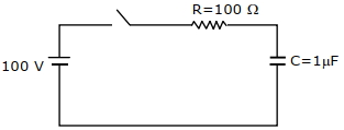
$A$ capacitor of capacitance $C = 1 \, \mu F$ is suddenly connected to a battery of $100 \, V$ through a resistance $R = 100 \, \Omega$. The time taken for the capacitor to be charged to $50 \, V$ is $.... \times 10^{-4} \, s$. (Take $\ln 2 = 0.69$)
A
$0.30$
B
$1.44$
C
$3.33$
D
$0.69$
Solution
(D) The instantaneous voltage $V$ across a charging capacitor is given by the formula: $V = V_0 (1 - e^{-t/RC})$.
Here,$V_0 = 100 \, V$,$V = 50 \, V$,$R = 100 \, \Omega$,and $C = 1 \, \mu F = 10^{-6} \, F$.
The time constant $\tau = RC = 100 \times 10^{-6} = 10^{-4} \, s$.
Substituting the values into the equation:
$50 = 100 (1 - e^{-t/10^{-4}})$
$0.5 = 1 - e^{-t/10^{-4}}$
$e^{-t/10^{-4}} = 0.5$
Taking the natural logarithm on both sides:
$-t/10^{-4} = \ln(0.5) = -\ln(2)$
$t/10^{-4} = \ln 2$
Given $\ln 2 = 0.69$,we get:
$t = 0.69 \times 10^{-4} \, s$.
Thus,the required value is $0.69$.
0 likes
View Solution103
DifficultMCQ
$A$ capacitor is discharging through a resistor $R$. Consider in time $t_{1}$,the energy stored in the capacitor reduces to half of its initial value and in time $t_{2}$,the charge stored reduces to one-eighth of its initial value. The ratio $t_{1} / t_{2}$ will be ................
A
$1/2$
B
$1/3$
C
$1/4$
D
$1/6$
Solution
(D) The energy stored in a capacitor is given by $U = \frac{q^2}{2C}$.
In time $t_{1}$,the energy reduces to half,so $U(t_{1}) = \frac{U_{0}}{2}$.
This implies $\frac{q(t_{1})^2}{2C} = \frac{1}{2} \frac{Q_{0}^2}{2C}$,which simplifies to $q(t_{1}) = \frac{Q_{0}}{\sqrt{2}}$.
Using the discharging equation $q(t) = Q_{0} e^{-t/RC}$,we have $\frac{Q_{0}}{\sqrt{2}} = Q_{0} e^{-t_{1}/RC}$,so $e^{-t_{1}/RC} = 2^{-1/2}$.
Taking the natural logarithm,$\frac{t_{1}}{RC} = \frac{1}{2} \ln(2)$.
In time $t_{2}$,the charge reduces to one-eighth,so $q(t_{2}) = \frac{Q_{0}}{8}$.
Using the discharging equation,$\frac{Q_{0}}{8} = Q_{0} e^{-t_{2}/RC}$,so $e^{-t_{2}/RC} = 2^{-3}$.
Taking the natural logarithm,$\frac{t_{2}}{RC} = 3 \ln(2)$.
Now,the ratio $\frac{t_{1}}{t_{2}} = \frac{\frac{1}{2} \ln(2)}{3 \ln(2)} = \frac{1}{6}$.
0 likes
View Solution104
DifficultMCQ
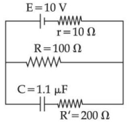
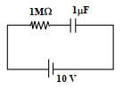
As shown in the figure,in steady state,the charge stored in the capacitor is $....... \times 10^{-6} \, C$.
A
$10$
B
$9$
C
$1$
D
$100$
Solution
(A) In steady state,the capacitor acts as an open circuit,so no current flows through the branch containing the capacitor.
The circuit effectively consists of the battery $E = 10 \, V$ with internal resistance $r = 10 \, \Omega$ connected in series with the resistor $R = 100 \, \Omega$.
The current $I$ in the circuit is given by $I = \frac{E}{R + r} = \frac{10}{100 + 10} = \frac{10}{110} = \frac{1}{11} \, A$.
The potential difference $V_R$ across the resistor $R = 100 \, \Omega$ is $V_R = I \times R = \frac{1}{11} \times 100 = \frac{100}{11} \, V$.
Since the capacitor is in parallel with the resistor $R$,the potential difference across the capacitor is equal to the potential difference across the resistor $R$.
The charge $q$ stored in the capacitor is $q = C \times V_R = (1.1 \times 10^{-6} \, F) \times \left(\frac{100}{11} \, V\right)$.
$q = (1.1 \times 10^{-6}) \times \left(\frac{100}{11}\right) = 0.1 \times 10^{-6} \times 100 = 10 \times 10^{-6} \, C$.
Therefore,the charge stored is $10 \times 10^{-6} \, C$.
0 likes
View Solution105
AdvancedMCQ
An initially uncharged capacitor $C$ is being charged by a battery of emf $E$ through a resistance $R$. Up to the instant when the capacitor is charged to a potential $E/2$, the ratio of the work done by the battery to the heat dissipated by the resistor is given by
A
$2: 1$
B
$3: 1$
C
$4: 3$
D
$4: 1$
Solution
(C) For a series $R-C$ circuit, the potential across the capacitor at time $t$ is given by $V(t) = E(1 - e^{-t/RC})$.
When the capacitor is charged to $E/2$, we have $E/2 = E(1 - e^{-t/RC})$, which implies $e^{-t/RC} = 1/2$.
The charge on the capacitor at this instant is $Q = C(E/2) = CE/2$.
The work done by the battery is $W = Q \cdot E = (CE/2) \cdot E = CE^2/2$.
The energy stored in the capacitor is $U = Q^2 / (2C) = (CE/2)^2 / (2C) = CE^2/8$.
According to the energy conservation principle, the work done by the battery is equal to the sum of the energy stored in the capacitor and the heat dissipated by the resistor: $W = U + H$.
Therefore, the heat dissipated $H = W - U = CE^2/2 - CE^2/8 = 3CE^2/8$.
The ratio of the work done by the battery to the heat dissipated is $W/H = (CE^2/2) / (3CE^2/8) = (1/2) / (3/8) = 4/3$.
0 likes
View Solution106
MediumMCQ
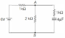
The circuit shown has been connected for a long time. The voltage across the capacitor is ............. $V$.
A
$1.2$
B
$2.0$
C
$2.4$
D
$4.0$
Solution
(D) After a long time,the capacitor is fully charged and acts as an open circuit. Therefore,no current flows through the branch containing the capacitor.
The equivalent circuit consists of the $6 \, V$ battery in series with the $1 \, k\Omega$ and $2 \, k\Omega$ resistors.
The total resistance of the circuit is $R_{eq} = 1 \, k\Omega + 2 \, k\Omega = 3 \, k\Omega$.
The current flowing through the circuit is $I = \frac{V}{R_{eq}} = \frac{6 \, V}{3 \times 10^3 \, \Omega} = 2 \times 10^{-3} \, A = 2 \, mA$.
The voltage across the $2 \, k\Omega$ resistor is $V_{AB} = I \times R = (2 \times 10^{-3} \, A) \times (2 \times 10^3 \, \Omega) = 4 \, V$.
Since the capacitor is in parallel with the $2 \, k\Omega$ resistor,the voltage across the capacitor is equal to the voltage across the $2 \, k\Omega$ resistor,which is $4 \, V$.
0 likes
View Solution107
DifficultMCQ
The capacitor of capacitance $C$ in the circuit shown is fully charged initially. The resistance is $R$. After the switch $S$ is closed,the time taken to reduce the stored energy in the capacitor to half its initial value is
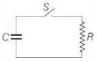
A
$\frac{R C}{2}$
B
$R C \ln 2$
C
$2 R C \ln 2$
D
$\frac{R C \ln 2}{2}$
Solution
(D) The energy stored in a capacitor is given by $U = \frac{q^2}{2C}$.
During the discharging of an $RC$ circuit,the charge on the capacitor at any time $t$ is given by $q = q_0 e^{-t / RC}$.
Substituting this into the energy formula,we get $U = \frac{(q_0 e^{-t / RC})^2}{2C} = \frac{q_0^2}{2C} e^{-2t / RC} = U_0 e^{-2t / RC}$,where $U_0$ is the initial energy.
We want the time $t$ when $U = \frac{U_0}{2}$.
Setting the equations equal: $\frac{U_0}{2} = U_0 e^{-2t / RC}$.
Dividing by $U_0$: $\frac{1}{2} = e^{-2t / RC}$.
Taking the natural logarithm on both sides: $\ln(1/2) = -2t / RC$.
Since $\ln(1/2) = -\ln 2$,we have $-\ln 2 = -2t / RC$.
Solving for $t$: $t = \frac{RC \ln 2}{2}$.
0 likes
View Solution108
EasyMCQ
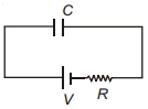
As shown in the figure,if a capacitor of capacitance $C$ is charged by connecting it with a resistance $R$ and a battery of $EMF$ $V$,then the total energy supplied by the battery is:
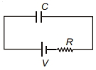
A
$\frac{1}{2} C V^2$
B
Less than $\frac{1}{2} C V^2$
C
$C V^2$
D
More than $C V^2$
Solution
(C) When a capacitor of capacitance $C$ is charged through a resistance $R$ by a battery of $EMF$ $V$,the charge $q$ on the capacitor at any time $t$ is given by $q = C V (1 - e^{-t/RC})$.
As $t \to \infty$,the final charge on the capacitor becomes $q_{final} = C V$.
The total charge supplied by the battery is $Q = C V$.
The work done by the battery (or energy supplied by the battery) is given by $W = Q V = (C V) V = C V^2$.
Note that the energy stored in the capacitor is $U = \frac{1}{2} C V^2$,which means half of the energy supplied by the battery is dissipated as heat in the resistor.
0 likes
View Solution109
EasyMCQ
$A$ capacitor of capacitance $C$ is charged with the help of a $200 \,V$ battery. It is then discharged through a small coil of resistance wire embedded in a thermally insulated block of specific heat capacity $2.5 \times 10^2 \,J/(kg \cdot K)$ and mass $0.1 \,kg$. If the temperature of the block rises by $0.4 \,K$,the value of $C$ is
A
$500 \,F$
B
$500 \,\mu F$
C
$50 \,F$
D
$50 \,\mu F$
Solution
(B) The energy stored in a capacitor is given by $U = \frac{1}{2} C V^2$.
When the capacitor discharges through the coil,this energy is converted into heat,which raises the temperature of the block.
The heat gained by the block is given by $Q = m s \Delta T$,where $m$ is the mass,$s$ is the specific heat capacity,and $\Delta T$ is the change in temperature.
Equating the energy stored to the heat gained: $\frac{1}{2} C V^2 = m s \Delta T$.
Given: $V = 200 \,V$,$m = 0.1 \,kg$,$s = 2.5 \times 10^2 \,J/(kg \cdot K)$,and $\Delta T = 0.4 \,K$.
Substituting the values: $\frac{1}{2} \times C \times (200)^2 = 0.1 \times 2.5 \times 10^2 \times 0.4$.
$\frac{1}{2} \times C \times 40000 = 10$.
$20000 \times C = 10$.
$C = \frac{10}{20000} = \frac{1}{2000} \,F$.
$C = 0.0005 \,F = 500 \times 10^{-6} \,F = 500 \,\mu F$.
0 likes
View Solution110
MediumMCQ
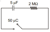
The following circuit consists of a $5 \,\mu F$ capacitor,having a charge of $50 \,\mu C$ as shown. The switch is closed at $t=0$. The value of the current in the $2 \,M \Omega$ resistor at $t=0$ is ........... $\mu A$.
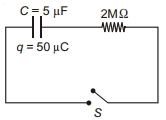
A
$1$
B
$2$
C
$5$
D
$6$
Solution
(C) At $t=0$,the potential difference across the capacitor is given by $V = \frac{q}{C}$.
Substituting the given values,$V = \frac{50 \,\mu C}{5 \,\mu F} = 10 \,V$.
When the switch is closed at $t=0$,the capacitor acts as a voltage source of $10 \,V$ connected to the $2 \,M \Omega$ resistor.
Using Ohm's law,the current $i$ in the circuit is $i = \frac{V}{R}$.
$i = \frac{10 \,V}{2 \times 10^6 \,\Omega} = 5 \times 10^{-6} \,A$.
Since $1 \,\mu A = 10^{-6} \,A$,the current is $5 \,\mu A$.
0 likes
View Solution111
EasyMCQ
Which of the following is a possible application of an $RC$ circuit?
A
Windshield wipers
B
Flashing red lights on roadway construction sites
C
Heart pacemakers
D
All of these
Solution
(D) An $RC$ circuit consists of a resistor and a capacitor connected in series or parallel. The time constant $\tau = RC$ determines the rate at which the capacitor charges or discharges.
$1$. Windshield wipers: $RC$ circuits are used to control the intermittent speed of wipers by setting the time delay between wipes.
$2$. Flashing lights: The charging and discharging cycle of the capacitor is used to trigger the flashing mechanism of warning lights.
$3$. Heart pacemakers: $RC$ timing circuits are used to regulate the electrical pulses sent to the heart at specific intervals.
Since all these devices rely on the time-dependent behavior of $RC$ circuits,the correct option is $D$.
0 likes
View Solution112
DifficultMCQ
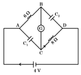
In the given figure,the resistance of the coil of the galvanometer $G$ is $2\,\Omega$. The emf of the cell is $4\,V$. The ratio of the potential difference across $C_1$ and $C_2$ is:
A
$1$
B
$\frac{4}{5}$
C
$\frac{3}{4}$
D
$\frac{5}{4}$
Solution
(B) At steady state,the capacitors act as open circuits. Therefore,no current flows through the branches containing the capacitors.
The current $i$ flows through the series combination of the $6\,\Omega$ resistor,the galvanometer resistance $(2\,\Omega)$,and the $8\,\Omega$ resistor.
The total resistance of the circuit is $R_{eq} = 6\,\Omega + 2\,\Omega + 8\,\Omega = 16\,\Omega$.
The current in the circuit is $i = \frac{V}{R_{eq}} = \frac{4\,V}{16\,\Omega} = 0.25\,A = \frac{1}{4}\,A$.
The potential difference across $C_1$ is the voltage across the branch $AC$. Since $C_1$ is in series with the $6\,\Omega$ resistor and the galvanometer,the voltage across $C_1$ is the potential difference between points $A$ and $C$. $V_1 = V_{AC} = i \times (6\,\Omega + 2\,\Omega) = \frac{1}{4} \times 8 = 2\,V$.
The potential difference across $C_2$ is the voltage across the branch $BD$. Since $C_2$ is in series with the galvanometer and the $8\,\Omega$ resistor,the voltage across $C_2$ is the potential difference between points $B$ and $D$. $V_2 = V_{BD} = i \times (2\,\Omega + 8\,\Omega) = \frac{1}{4} \times 10 = 2.5\,V$.
The ratio of the potential difference across $C_1$ and $C_2$ is $\frac{V_1}{V_2} = \frac{2}{2.5} = \frac{4}{5}$.
0 likes
View Solution113
DifficultMCQ
The electric field between the two parallel plates of a capacitor of $1.5 \mu F$ capacitance drops to one third of its initial value in $6.6 \mu s$ when the plates are connected by a thin wire. The resistance of this wire is . . . . . . . $\Omega$. (Given,$\log_{e} 3 = 1.1$)
A
$2$
B
$3$
C
$4$
D
$6$
Solution
(C) The electric field $E$ between the plates is proportional to the potential difference $V$ across the capacitor $(E = V/d)$.
Given that the electric field drops to one-third of its initial value,the potential difference also drops to one-third: $V = V_0 / 3$.
The discharging equation for a capacitor is $V = V_0 e^{-t/\tau}$,where $\tau = RC$ is the time constant.
Substituting the given values: $V_0 / 3 = V_0 e^{-t/\tau} \Rightarrow 1/3 = e^{-t/\tau}$.
Taking the natural logarithm on both sides: $\ln(3) = t/\tau$.
Given $\ln(3) = 1.1$,$t = 6.6 \times 10^{-6} \ s$,and $C = 1.5 \times 10^{-6} \ F$.
$1.1 = (6.6 \times 10^{-6}) / (R \times 1.5 \times 10^{-6})$.
$1.1 = 6.6 / (1.5 \times R)$.
$R = 6.6 / (1.5 \times 1.1) = 6.6 / 1.65 = 4 \ \Omega$.
1 likes
View Solution114
AdvancedMCQ
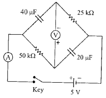
In the circuit shown below,the key is pressed at time $t=0$. Which of the following statement$(s)$ is(are) true?
$(A)$ The voltmeter displays $-5 \ V$ as soon as the key is pressed,and displays $+5 \ V$ after a long time.
$(B)$ The voltmeter will display $0 \ V$ at time $t=\ln 2 \ s$.
$(C)$ The current in the ammeter becomes $1/e$ of the initial value after $1 \ s$.
$(D)$ The current in the ammeter becomes zero after a long time.
A
$A, B, C$
B
$A, B, C, D$
C
$A, C, D$
D
$B, C, D$
Solution
(B) At $t=0$,capacitors are uncharged,so they act as short circuits. The voltmeter is connected across the junction of the two branches. Initially,the potential at the top node is $0 \ V$ and at the bottom node is $5 \ V$ (relative to the negative terminal),so the voltmeter reads $-5 \ V$. After a long time,capacitors are fully charged and act as open circuits. The circuit behaves as a voltage divider. The potential at the top node becomes $5 \ V$ and at the bottom node $0 \ V$,so the voltmeter reads $+5 \ V$. Thus,$(A)$ is true.
The potential difference across the voltmeter $V_v = V_{top} - V_{bottom}$. Using the time-dependent charging equations for the $RC$ circuits,we find $V_v(t) = 5(2e^{-t} - 1)$. Setting $V_v = 0$ gives $2e^{-t} = 1$,or $t = \ln 2 \ s$. Thus,$(B)$ is true.
The total current $I(t) = I_1(t) + I_2(t) = I_0 e^{-t/\tau}$. The time constant for both branches is $\tau = RC = (50 \times 10^3 \Omega)(20 \times 10^{-6} F) = 1 \ s$. Thus,$I(t) = I_0 e^{-t}$. At $t = 1 \ s$,$I = I_0/e$. Thus,$(C)$ is true.
After a long time,capacitors are fully charged,acting as open circuits,so the current in the ammeter becomes zero. Thus,$(D)$ is true.
Therefore,all statements $(A, B, C, D)$ are true.
0 likes
View Solution115
AdvancedMCQ
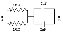
At time $t=0$,a battery of $10 \ V$ is connected across points $A$ and $B$ in the given circuit. If the capacitors have no charge initially,at what time (in seconds) does the voltage across them become $4 \ V$? [Take $\ln 5=1.6, \ln 3=1.1$]
A
$1$
B
$2$
C
$3$
D
$4$
Solution
(B) First,calculate the equivalent resistance $R_{eq}$ and equivalent capacitance $C_{eq}$ of the circuit.
Two resistors of $2 \ M\Omega$ are in parallel,so $R_{eq} = \frac{2 \times 2}{2 + 2} \ M\Omega = 1 \ M\Omega = 10^6 \ \Omega$.
Two capacitors of $2 \ \mu F$ are in parallel,so $C_{eq} = 2 + 2 = 4 \ \mu F = 4 \times 10^{-6} \ F$.
The time constant $\tau = R_{eq} C_{eq} = (10^6 \ \Omega) \times (4 \times 10^{-6} \ F) = 4 \ s$.
The voltage across the capacitors at time $t$ is given by $V(t) = V_0(1 - e^{-t/\tau})$.
Given $V(t) = 4 \ V$,$V_0 = 10 \ V$,and $\tau = 4 \ s$,we have:
$4 = 10(1 - e^{-t/4})$
$0.4 = 1 - e^{-t/4}$
$e^{-t/4} = 0.6 = \frac{3}{5}$
Taking the natural logarithm on both sides:
$-t/4 = \ln(3/5) = \ln 3 - \ln 5$
$-t/4 = 1.1 - 1.6 = -0.5$
$t/4 = 0.5$
$t = 2 \ s$.
0 likes
View Solution116
MediumMCQ
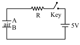
Identify the valid statements relevant to the given circuit at the instant when the key is closed.
$A.$ There will be no current through resistor $R.$
$B.$ There will be maximum current in the connecting wires.
$C.$ Potential difference between the capacitor plates $A$ and $B$ is minimum.
$D.$ Charge on the capacitor plates is minimum.
Choose the correct answer from the options given below $:$
$A.$ There will be no current through resistor $R.$
$B.$ There will be maximum current in the connecting wires.
$C.$ Potential difference between the capacitor plates $A$ and $B$ is minimum.
$D.$ Charge on the capacitor plates is minimum.
Choose the correct answer from the options given below $:$
A
$C, D$ only
B
$B, C, D$ only
C
$A, C$ only
D
$A, B, D$ only
Solution
(B) At the instant the key is closed $(t = 0)$,the capacitor is uncharged.
An uncharged capacitor acts as a short circuit (zero resistance) at the initial instant.
Therefore,the current in the circuit is maximum,given by $I = V/R$.
Since the capacitor is uncharged,the charge $Q$ on the plates is zero (minimum).
The potential difference across the capacitor is $V_c = Q/C = 0$ (minimum).
Thus,statements $B, C,$ and $D$ are correct.
Therefore,the correct option is $B$.
0 likes
View Solution117
MediumMCQ
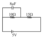
At steady state,the charge on the capacitor,as shown in the circuit below,is . . . . . . $\mu \text{C}.$
A
$14$
B
$13$
C
$16$
D
$19$
Solution
(C) In a steady state,the capacitor acts as an open circuit,meaning no current flows through the branch containing the capacitor. The circuit simplifies to a series combination of two resistors ($10 \ \Omega$ and $15 \ \Omega$) connected to a $5 \ \text{V}$ battery.
$1$. Calculate the total current in the circuit:
$I = \frac{V}{R_{eq}} = \frac{5 \ \text{V}}{10 \ \Omega + 15 \ \Omega} = \frac{5}{25} \ \text{A} = 0.2 \ \text{A}$.
$2$. Calculate the potential difference $(V_c)$ across the $10 \ \Omega$ resistor,which is also the potential difference across the capacitor:
$V_c = I \times R = 0.2 \ \text{A} \times 10 \ \Omega = 2 \ \text{V}$.
$3$. Calculate the charge $(Q)$ on the capacitor using $Q = CV$:
$Q = (8 \ \mu \text{F}) \times (2 \ \text{V}) = 16 \ \mu \text{C}$.
0 likes
View Solution118
MediumMCQ
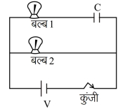
After closing the key in the given circuit:
$(a)$ Bulb $(2)$ will glow and maintain its brightness.
$(b)$ Brightness of bulb $(1)$ will gradually decrease and at steady state it goes completely dark.
$(a)$ Bulb $(2)$ will glow and maintain its brightness.
$(b)$ Brightness of bulb $(1)$ will gradually decrease and at steady state it goes completely dark.
A
Both incorrect.
B
$1^{\text{st}}$ correct only.
C
$2^{\text{nd}}$ correct only.
D
Both correct.
Solution
(D) When the key is closed,the circuit consists of two parallel branches connected to a $DC$ voltage source $V$.
In the branch containing bulb $(2)$,the current is $I_2 = V/R_2$,where $R_2$ is the resistance of bulb $(2)$. This current is constant,so bulb $(2)$ glows with constant brightness.
In the branch containing bulb $(1)$ and capacitor $C$,the capacitor starts charging. Initially,it acts as a short circuit,allowing maximum current to flow. As the capacitor charges,the potential difference across it increases,opposing the source voltage.
At steady state,the capacitor is fully charged and acts as an open circuit (infinite resistance),so the current in this branch becomes zero. Thus,bulb $(1)$ gradually dims and eventually goes dark.
Therefore,both statements $(a)$ and $(b)$ are correct.
0 likes
View Solution119
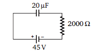
MediumMCQ
$A$ $20 \mu F$ capacitor is connected to a $45 \text{ V}$ battery through a circuit whose resistance is $2000 \Omega$. What is the final charge on the capacitor?
A
$9 \times 10^{-4} \text{ C}$
B
$9.154 \times 10^{-4} \text{ C}$
C
$9.8 \times 10^{-4} \text{ C}$
D
None of these
Solution
(A) We know that in the steady state,the capacitor behaves like an open circuit,meaning no current flows through it.
Therefore,the potential difference across the capacitor is equal to the battery voltage,which is $45 \text{ V}$.
The final charge $q$ on the capacitor is given by the formula:
$q = C \times V$
Given:
Capacitance $C = 20 \mu F = 20 \times 10^{-6} \text{ F}$
Voltage $V = 45 \text{ V}$
Substituting the values:
$q = 20 \times 10^{-6} \times 45$
$q = 900 \times 10^{-6} \text{ C}$
$q = 9 \times 10^{-4} \text{ C}$
0 likes
View Solution120
MediumMCQ
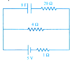
$A$ capacitor of $8 \mu\text{F}$ is connected as shown in the circuit. Find the charge on the plates of the capacitor. (in $\mu\text{C}$)
A
$32$
B
$40$
C
$0$
D
$80$
Solution
(A) In a steady state, the capacitor acts as an open circuit, meaning no current flows through the branch containing the capacitor.
Therefore, the current $I$ in the circuit flows only through the battery and the $4 \Omega$ resistor.
The total resistance of the circuit is $R_{eq} = 4 \Omega + 1 \Omega = 5 \Omega$.
The current in the circuit is $I = \frac{E}{R_{eq}} = \frac{5 \text{V}}{5 \Omega} = 1 \text{A}$.
The potential difference across the $4 \Omega$ resistor is $V = I \times R = 1 \text{A} \times 4 \Omega = 4 \text{V}$.
Since the capacitor is connected in parallel with the $4 \Omega$ resistor, the potential difference across the capacitor is also $4 \text{V}$.
The charge on the capacitor is $Q = C \times V = 8 \mu\text{F} \times 4 \text{V} = 32 \mu\text{C}$.
0 likes
View Solution121
EasyMCQ
When a capacitor is connected to a battery,
A
an alternating current flows in the circuit.
B
no current flows in the circuit.
C
a current flows for some time and finally it decreases to zero.
D
current keeps on increasing and reaches maximum after some time.
Solution
(C) When a capacitor is connected to a battery ($DC$ source),the capacitor begins to charge.
Initially,the potential difference across the capacitor is zero,so the current is maximum.
As the capacitor charges,the potential difference across it increases,which opposes the flow of charge.
Consequently,the current decreases exponentially.
Once the capacitor is fully charged,the potential difference across the capacitor equals the battery voltage,and the current becomes zero.
Thus,a transient current flows for some time and finally decreases to zero.
0 likes
View Solution122
EasyMCQ
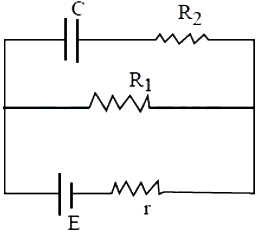
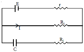
In the circuit given,the charge on the capacitor is
A
$C E$
B
$\frac{C E R_1}{R_1+r}$
C
$\frac{C E R_2}{R_1+r}$
D
$\frac{C E R_1}{R_2+r}$
Solution
(B) In a steady state,the capacitor acts as an open circuit,meaning no current flows through the branch containing the capacitor.
Therefore,the entire current $I$ flows through the resistor $R_1$ and the internal resistance $r$ of the battery.
The total resistance of the circuit is $R_{total} = R_1 + r$.
The current in the circuit is $I = \frac{E}{R_1 + r}$.
The potential difference across the resistor $R_1$ is $V = I R_1 = \frac{E R_1}{R_1 + r}$.
Since the capacitor is connected in parallel with the resistor $R_1$,the potential difference across the capacitor is equal to the potential difference across $R_1$.
Thus,the potential difference across the capacitor is $V_C = \frac{E R_1}{R_1 + r}$.
The charge on the capacitor is given by $Q = C V_C$.
Substituting the value of $V_C$,we get $Q = C \left( \frac{E R_1}{R_1 + r} \right) = \frac{C E R_1}{R_1 + r}$.
0 likes
View Solution123
MediumMCQ
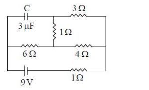
In the given circuit, the potential difference across the plates of the capacitor $C$ in steady state is (in $V$)
A
$6.5$
B
$6$
C
$9$
D
$7.5$
Solution
(B) In steady state, the capacitor $C$ acts as an open circuit, so no current flows through the branch containing the capacitor.
Let the potential at the negative terminal of the $9 \text{ V}$ battery be $0 \text{ V}$. Then the potential at the positive terminal is $9 \text{ V}$.
The circuit simplifies to a series combination of the $6 \text{ }\Omega$ and $4 \text{ }\Omega$ resistors, with the $1 \text{ }\Omega$ resistor in series with the battery.
The total resistance of the circuit is $R_{eq} = 6 \text{ }\Omega + 4 \text{ }\Omega + 1 \text{ }\Omega = 11 \text{ }\Omega$.
The current in the circuit is $I = \frac{V}{R_{eq}} = \frac{9 \text{ V}}{11 \text{ }\Omega} = \frac{9}{11} \text{ A}$.
The potential at the junction between the $6 \text{ }\Omega$ and $4 \text{ }\Omega$ resistors is $V_x = 9 \text{ V} - I \times 6 \text{ }\Omega = 9 - (\frac{9}{11} \times 6) = 9 - \frac{54}{11} = \frac{45}{11} \text{ V}$.
The capacitor is connected in parallel with the $6 \text{ }\Omega$ resistor branch (including the $3 \text{ }\Omega$ resistor which carries no current). Thus, the potential difference across the capacitor is equal to the potential difference across the $6 \text{ }\Omega$ resistor, which is $\frac{45}{11} \text{ V} \approx 4.09 \text{ V}$.
Wait, re-evaluating the circuit: The capacitor is in parallel with the $6 \text{ }\Omega$ resistor. The potential difference across the capacitor is $V_C = 6 \text{ V}$.
0 likes
View Solution124
EasyMCQ
In a $CR$ circuit, the growth of charge on the capacitor is
A
more rapid if the $CR$ is smaller
B
more rapid if the $CR$ is larger
C
independent of $CR$
D
independent of time
Solution
(A) The growth of charge $Q$ on a capacitor in a $CR$ circuit is given by the equation: $Q = Q_0(1 - e^{-t/RC})$.
Here, the term $RC$ is known as the time constant $(\tau)$ of the circuit.
The time constant determines the rate at which the capacitor charges.
If the product $CR$ is smaller, the time constant is smaller, which means the capacitor reaches its maximum charge more quickly.
Therefore, the growth of charge is more rapid if the $CR$ value is smaller.
0 likes
View Solution125
DifficultMCQ
$A$ capacitor of capacity $0.1 \mu F$ connected in series to a resistor of $10 M \Omega$ is charged to a certain potential and then made to discharge through the resistor. The time in which the potential will take to fall to half its original value is (Given, $\log _{10} 2=0.3010$ ) (in $\,s$)
A
$2$
B
$0.693$
C
$0.5$
D
$1.0$
Solution
(B) The potential across a discharging capacitor is given by $V = V_0 e^{-t/RC}$.
We want to find the time $t$ when $V = V_0/2$.
Substituting this into the equation: $V_0/2 = V_0 e^{-t/RC}$.
This simplifies to $1/2 = e^{-t/RC}$, or $e^{t/RC} = 2$.
Taking the natural logarithm on both sides: $t/RC = \ln(2)$.
Using the conversion $\ln(2) = 2.3026 \times \log_{10}(2)$, we get $t = RC \times 2.3026 \times 0.3010$.
Given $C = 0.1 \mu F = 0.1 \times 10^{-6} F$ and $R = 10 M \Omega = 10 \times 10^6 \Omega$.
Calculating the time constant: $RC = (0.1 \times 10^{-6}) \times (10 \times 10^6) = 1 \ s$.
Therefore, $t = 1 \times 2.3026 \times 0.3010 \approx 0.693 \ s$.
0 likes
View Solution126
DifficultMCQ
The time in seconds required to produce a potential difference of $20 \ V$ across a capacitor of $1000 \ \mu F$ when it is charged at a steady rate of $200 \ \mu C/s$ is
A
$50$
B
$100$
C
$150$
D
$200$
Solution
(B) The charge $Q$ on a capacitor is given by the formula $Q = C \times V$,where $C$ is the capacitance and $V$ is the potential difference.
Given $C = 1000 \ \mu F = 1000 \times 10^{-6} \ F$ and $V = 20 \ V$.
Total charge $Q = 1000 \times 10^{-6} \ F \times 20 \ V = 20,000 \ \mu C$.
The rate of charging is given as $I = 200 \ \mu C/s$.
Since the rate is steady,the time $t$ required is given by $t = Q / I$.
$t = 20,000 \ \mu C / 200 \ \mu C/s = 100 \ s$.
0 likes
View Solution127
EasyMCQ
In a $RC$ circuit,where $R$ is resistance and $C$ is capacitance,which of the following has the dimension of time?
A
$R/C$
B
$C/R$
C
$\sqrt{RC}$
D
$RC$
Solution
(D) In an $RC$ circuit,the charge $q$ on the capacitor at time $t$ is given by $q(t) = q_0(1 - e^{-t/RC})$.
Since the exponent of the exponential function must be dimensionless,the term $t/RC$ must be dimensionless.
Therefore,the dimensions of $RC$ must be equal to the dimensions of time $t$.
Thus,the time constant of an $RC$ circuit is $\tau = RC$,which has the dimension of time.
Since the exponent of the exponential function must be dimensionless,the term $t/RC$ must be dimensionless.
Therefore,the dimensions of $RC$ must be equal to the dimensions of time $t$.
Thus,the time constant of an $RC$ circuit is $\tau = RC$,which has the dimension of time.
0 likes
View Solution128
EasyMCQ
An electric bulb,a capacitor,a battery,and a switch are all connected in series in a circuit. How does the intensity of light vary when the switch is turned on?
A
Continues to increase gradually
B
Gradually increases for sometime and then becomes steady
C
Sharply rises initially and then gradually decreases
D
Gradually increases for sometime and then gradually decreases
Solution
(C) When the switch is turned on,the capacitor begins to charge. Initially,the charge on the capacitor is $0$,so the potential difference across it is $0 \ V$. Consequently,the entire battery voltage appears across the bulb,causing it to glow with maximum intensity.
As the capacitor charges,the potential difference across it $(V_c = q/C)$ increases over time. According to Kirchhoff's voltage law,the voltage across the bulb $(V_b)$ is given by $V_b = V_{battery} - V_c$. As $V_c$ increases,$V_b$ decreases.
Therefore,the intensity of the light,which depends on the power dissipated by the bulb $(P = V_b^2 / R)$,will be maximum at the start and will gradually decrease as the capacitor becomes fully charged.
0 likes
View Solution129
MediumMCQ
The charge on the capacitor of capacitance $C$ shown in the figure below will be
A
$CE$
B
$\frac{CE R}{R_1+r}$
C
$\frac{C E R_2}{R_2+r}$
D
$\frac{C E R_1}{R_2+r}$
Solution
(C) In the steady state,the capacitor acts as an open circuit,meaning no current flows through the branch containing the capacitor.
Therefore,the current $I$ flows only through the branch containing the resistor $R_2$ and the internal resistance $r$ of the battery.
Using Ohm's law,the current in the circuit is $I = \frac{E}{R_2 + r}$.
The potential difference $V$ across the capacitor is equal to the potential difference across the resistor $R_2$,because they are connected in parallel.
Thus,$V = I R_2 = \frac{E R_2}{R_2 + r}$.
The charge $Q$ on the capacitor is given by $Q = CV$.
Substituting the value of $V$,we get $Q = C \left( \frac{E R_2}{R_2 + r} \right) = \frac{C E R_2}{R_2 + r}$.
0 likes
View Solution130
MediumMCQ
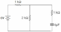
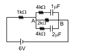
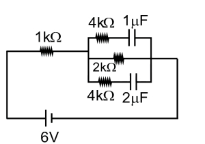
What are the charges stored in the $1 \mu F$ and $2 \mu F$ capacitors in the circuit as shown in the figure once the current $(I)$ becomes steady?
A
$8 \mu C$ and $4 \mu C$
B
$4 \mu C$ and $8 \mu C$
C
$3 \mu C$ and $6 \mu C$
D
$6 \mu C$ and $3 \mu C$
Solution
(B) In a steady state, the capacitors act as open circuits, so no current flows through the branches containing the capacitors.
Therefore, the current $(I)$ flows only through the $1 \text{ k}\Omega$ resistor and the $2 \text{ k}\Omega$ resistor in series.
The total resistance of the circuit is $R_{eq} = 1 \text{ k}\Omega + 2 \text{ k}\Omega = 3 \text{ k}\Omega = 3000 \Omega$.
The current in the circuit is $I = \frac{V}{R_{eq}} = \frac{6 \text{ V}}{3000 \Omega} = 2 \times 10^{-3} \text{ A} = 2 \text{ mA}$.
The potential difference across the $2 \text{ k}\Omega$ resistor is $V_{AB} = I \times R = (2 \times 10^{-3} \text{ A}) \times (2000 \Omega) = 4 \text{ V}$.
Since the capacitors are in parallel with the $2 \text{ k}\Omega$ resistor, the potential difference across both capacitors is $4 \text{ V}$.
The charge on the $1 \mu F$ capacitor is $q_1 = C_1 \times V = (1 \mu F) \times (4 \text{ V}) = 4 \mu C$.
The charge on the $2 \mu F$ capacitor is $q_2 = C_2 \times V = (2 \mu F) \times (4 \text{ V}) = 8 \mu C$.
0 likes
View Solution131
EasyMCQ
$A$ capacitor of capacitance $C$ is connected in series with a resistance $R$ and a $DC$ source of $emf$ $E$ through a key. The capacitor starts charging when the key is closed. By the time the capacitor has been fully charged,what amount of energy is dissipated in the resistance $R$?
A
$\frac{1}{2} C E^{2}$
B
$0$
C
$C E^{2}$
D
$\frac{E^{2}}{R}$
Solution
(A) When the capacitor is fully charged,the charge on it is $q = CE$.
The total work done by the $DC$ source (battery) is $W = qE = (CE)E = CE^2$.
The energy stored in the capacitor is $U = \frac{1}{2} CE^2$.
According to the law of conservation of energy,the work done by the battery is equal to the sum of the energy stored in the capacitor and the energy dissipated as heat in the resistor $R$.
Therefore,the energy dissipated in the resistance $R$ is given by:
$H = W - U$
$H = CE^2 - \frac{1}{2} CE^2$
$H = \frac{1}{2} CE^2$.
0 likes
View Solution132
MediumMCQ
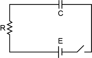
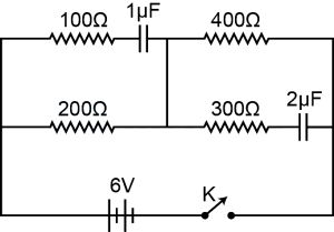
What will be the current through the $200 \Omega$ resistor in the given circuit,a long time after the switch $K$ is closed?
A
Zero
B
$100 mA$
C
$10 mA$
D
$1 mA$
Solution
(C) In a steady state,a capacitor acts as an open circuit,meaning no direct current flows through the branches containing capacitors.
Therefore,we can neglect the branches with the $1 \mu F$ and $2 \mu F$ capacitors.
The circuit simplifies to a single series loop containing the $6 V$ battery,the $200 \Omega$ resistor,and the $400 \Omega$ resistor.
The total resistance of the circuit is $R_{\text{net}} = 200 \Omega + 400 \Omega = 600 \Omega$.
Using Ohm's law,the current $I$ in the circuit is:
$I = \frac{V}{R_{\text{net}}} = \frac{6 V}{600 \Omega} = 0.01 A$.
Converting to milliamperes,$I = 0.01 \times 1000 mA = 10 mA$.
0 likes
View Solution133
MediumMCQ
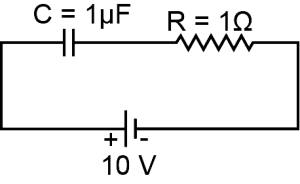
$A$ $1 \mu F$ capacitor $C$ is connected to a battery of $10 V$ through a resistance of $1 \text{ M}\Omega$. The voltage across $C$ after $1 \text{ s}$ is approximately: (in $V$)
A
$5.6$
B
$7.8$
C
$6.3$
D
$10$
Solution
(C) The time constant $\tau$ of an $RC$ circuit is given by $\tau = R \cdot C$.
Given:
$C = 1 \mu F = 1 \times 10^{-6} F$
$R = 1 \text{ M}\Omega = 1 \times 10^{6} \Omega$
Therefore, $\tau = (1 \times 10^{6} \Omega) \times (1 \times 10^{-6} F) = 1 \text{ s}$.
The voltage across a charging capacitor at time $t$ is given by $V(t) = V_0(1 - e^{-t/\tau})$.
Substituting $t = 1 \text{ s}$ and $\tau = 1 \text{ s}$:
$V(1) = 10(1 - e^{-1/1}) = 10(1 - e^{-1})$.
Since $e^{-1} \approx 0.37$, we have:
$V(1) \approx 10(1 - 0.37) = 10(0.63) = 6.3 V$.
Thus, the voltage across the capacitor after $1 \text{ s}$ is approximately $6.3 V$.
0 likes
View Solution134
MediumMCQ
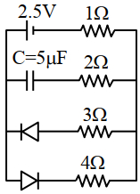
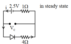
The charge stored by the capacitor $C$ in the given circuit in the steady state is . . . . . . $\mu C$.
A
$12.5$
B
$10$
C
$7.5$
D
$5$
Solution
(B) In the steady state,the capacitor acts as an open circuit,so no current flows through the branch containing the capacitor.
Looking at the circuit,the diode in the branch with $3 \Omega$ is reverse-biased,so no current flows through that branch.
The diode in the branch with $4 \Omega$ is forward-biased,so current flows through the branch containing the $2.5 \text{ V}$ battery,the $1 \Omega$ resistor,and the $4 \Omega$ resistor.
The total resistance in this path is $R_{eq} = 1 \Omega + 4 \Omega = 5 \Omega$.
The current in the circuit is $i = \frac{V}{R_{eq}} = \frac{2.5 \text{ V}}{5 \Omega} = 0.5 \text{ A}$.
The voltage across the capacitor $V_C$ is equal to the voltage across the $4 \Omega$ resistor because they are in parallel.
$V_C = i \times 4 \Omega = 0.5 \text{ A} \times 4 \Omega = 2 \text{ V}$.
The charge stored by the capacitor is $Q = C \times V_C = 5 \mu\text{F} \times 2 \text{ V} = 10 \mu\text{C}$.
0 likes
View Solution135
MediumMCQ
$A$ filter circuit used in a rectifier has a load resistance of $200 \Omega$ and a capacitance of $15 \mu\text{F}$. The value of the time constant is . . . . . . .
A
$1.33 \text{ ms}$
B
$3 \text{ ms}$
C
$7.5 \text{ ms}$
D
$0.3 \mu\text{s}$
Solution
(B) The time constant $\tau$ for an $RC$ circuit is defined as the product of resistance $R$ and capacitance $C$: $\tau = R \times C$.
Given values are $R = 200 \Omega$ and $C = 15 \mu\text{F} = 15 \times 10^{-6} \text{ F}$.
Substituting these values into the formula:
$\tau = 200 \Omega \times 15 \times 10^{-6} \text{ F}$
$\tau = 3000 \times 10^{-6} \text{ s}$
$\tau = 3 \times 10^{-3} \text{ s} = 3 \text{ ms}$.
Therefore,the correct option is $(B)$.
0 likes
View Solution136
DifficultMCQ
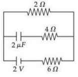
Under steady state condition,the potential difference across the capacitor in the circuit is . . . . . . $V$.
A
$0.5$
B
$1.5$
C
$0$
D
$2$
Solution
(B) In steady state,the capacitor acts as an open circuit,meaning no current flows through the branch containing the capacitor.
Therefore,the current in the circuit flows only through the $2\Omega$ and $6\Omega$ resistors which are in series with the $2\text{V}$ battery.
The total resistance of the circuit is $R = 2\Omega + 6\Omega = 8\Omega$.
The current in the circuit is $I = V / R = 2\text{V} / 8\Omega = 0.25\text{A}$.
The potential difference across the $6\Omega$ resistor is $V_6 = I \times 6\Omega = 0.25\text{A} \times 6\Omega = 1.5\text{V}$.
Since the capacitor branch is in parallel with the $6\Omega$ resistor,the potential difference across the capacitor is equal to the potential difference across the $6\Omega$ resistor.
Thus,the potential difference across the capacitor is $1.5\text{V}$.
0 likes
View Solution137
DifficultMCQ
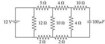
The stored charge in the capacitor in steady state of the following circuit is . . . . . . $\mu C$.
A
$20$
B
$30$
C
$40$
D
$50$
Solution
(C) In steady state, the capacitor acts as an open circuit. No current flows through the branch containing the capacitor.
Let the potential at the node between the $5 \Omega$ and $4 \Omega$ resistors be $V_1$, and the potential at the node between the $4 \Omega$ and $10 \Omega$ resistors be $V_2$.
Since the capacitor is in series with the $10 \Omega$ resistor, the potential across the capacitor is equal to the potential at node $V_2$ (assuming the bottom wire is at $0 V$).
Using nodal analysis, the circuit simplifies to a voltage divider network. The equivalent resistance of the network is calculated, and the voltage at the node connected to the capacitor is found to be $0.4 V$.
Thus, the charge $Q = C \times V = 100 \mu F \times 0.4 V = 40 \mu C$.
0 likes
View SolutionElectric Potential and Capacitance — Charging and Discharging of Capacitance and RC circuit (DC) · Frequently Asked Questions
1Are these Electric Potential and Capacitance questions useful for JEE and NEET?
Yes. All questions in this section are mapped to JEE Main and NEET exam patterns. Previous year questions from JEE Main, NEET, GUJCET and state-level exams are included with full solutions.
2Can I switch to Hindi or Gujarati for these questions?
Yes. Use the language tabs in the hero section or the sidebar to view the same questions and solutions in English, Hindi or Gujarati.
3How do I generate a question paper from this subtopic?
Use the Vedclass Exam Paper Generator — select the chapter and subtopic, set difficulty, and generate Sets A, B, C, D automatically. First 3 chapters of every subject are free.
Vedclass Products
For Students
Vedclass Test Series
Mock tests in real JEE/NEET style with performance analysis. 5-day free trial.
Start Free TrialFor Teachers
Exam Paper Generator
Generate Set A/B/C/D papers from this chapter in 2 minutes. 3 chapters free.
Try FreeFor Institutes
Online Exam Module
Live online exams with unlimited students, 360° analytics & white-label branding.
See DemoFor Teachers & Institutes
Generate a Electric Potential and Capacitance Exam Paper in 2 Minutes
Select subtopic & difficulty — Sets A, B, C, D auto-generated with No Repeat logic.
First 3 chapters of every subject are free — no payment required.