
A English
Mix Examples-Current Electricity Questions in English
Class 12 Physics · Current Electricity · Mix Examples-Current Electricity
255+
Questions
English
Language
100%
With Solutions
Showing 50 of 255 questions in English
151
DifficultMCQ
The charge flowing through a resistance $R$ varies with time as $Q = 2t - 8t^2$. The total heat produced in the resistance is (for $0 \leq t \leq \frac{1}{8} \ s$)
A
$\frac{R}{6} \ J$
B
$\frac{R}{3} \ J$
C
$\frac{R}{2} \ J$
D
$R \ J$
Solution
(A) The charge flowing through the resistor is given by $Q = 2t - 8t^2$.
The current $I$ is the rate of change of charge with respect to time:
$I = \frac{dQ}{dt} = \frac{d}{dt}(2t - 8t^2) = 2 - 16t$.
The heat produced $H$ in a resistor $R$ over a time interval is given by the integral:
$H = \int_{0}^{t} I^2 R \ dt$.
Substituting the limits $0$ to $\frac{1}{8}$:
$H = \int_{0}^{1/8} (2 - 16t)^2 R \ dt$
$H = R \int_{0}^{1/8} (4 - 64t + 256t^2) \ dt$
$H = R \left[ 4t - 32t^2 + \frac{256t^3}{3} \right]_{0}^{1/8}$
Evaluating at the limits:
$H = R \left[ 4(\frac{1}{8}) - 32(\frac{1}{8})^2 + \frac{256}{3}(\frac{1}{8})^3 \right]$
$H = R \left[ \frac{1}{2} - 32(\frac{1}{64}) + \frac{256}{3}(\frac{1}{512}) \right]$
$H = R \left[ \frac{1}{2} - \frac{1}{2} + \frac{1}{6} \right] = \frac{R}{6} \ J$.
0 likes
View Solution152
MediumMCQ
Three $60\, W$ light bulbs are mistakenly wired in series and connected to a $120\, V$ power supply. Assume the light bulbs are rated for single connection to $120\, V$. With the mistaken connection,the power dissipated by each bulb is: .................. $W$
A
$6.7$
B
$13.3$
C
$20$
D
$40$
Solution
(A) The rated power $P_r = 60\, W$ at rated voltage $V_r = 120\, V$. The resistance of each bulb is $R = \frac{V_r^2}{P_r} = \frac{120^2}{60} = 240\, \Omega$.
When three identical bulbs are connected in series to a $120\, V$ supply,the total resistance is $R_{eq} = 3R = 3 \times 240 = 720\, \Omega$.
The current flowing through the series circuit is $I = \frac{V}{R_{eq}} = \frac{120}{720} = \frac{1}{6}\, A$.
The power dissipated by each bulb is $P = I^2 R = (\frac{1}{6})^2 \times 240 = \frac{1}{36} \times 240 = \frac{240}{36} = 6.67\, W \approx 6.7\, W$.
0 likes
View Solution153
MediumMCQ
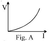
The variation of current $(I)$ and voltage $(V)$ is as shown in figure $A$. The variation of power $P$ with current $I$ is best shown by which of the following graphs?
A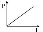
B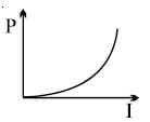
C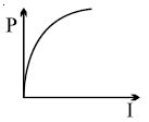
D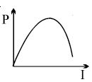
Solution
(B) From the given figure $A$,we observe that the voltage $V$ increases non-linearly with current $I$,specifically $V$ is proportional to $I^n$ where $n > 1$ (as it is a concave-up curve).
Power $P$ is defined as $P = V \times I$.
Substituting $V \propto I^n$,we get $P \propto I^n \times I = I^{n+1}$.
Since $n > 1$,the exponent $n+1$ is greater than $2$. This implies that the graph of $P$ versus $I$ will also be a concave-up curve,similar to the original $V-I$ graph but with a steeper increase.
Comparing this with the given options,the graph in option $B$ represents an upward-curving (concave-up) relationship,which is consistent with $P \propto I^{n+1}$ where $n+1 > 2$.
Therefore,option $B$ is the correct representation.
0 likes
View Solution154
MediumMCQ
An ammeter $A$ of finite resistance and a resistor $R$ are joined in series to an ideal cell $C$. $A$ potentiometer $P$ is joined in parallel to $R$. The ammeter reading is $I_0$ and the potentiometer reading is $V_0$. $P$ is now replaced by a voltmeter of finite resistance. The ammeter reading now is $I$ and the voltmeter reading is $V$.

A
$I > I_0, V < V_0$
B
$I > I_0, V = V_0$
C
$I = I_0, V < V_0$
D
$I < I_0, V = V_0$
Solution
(A) potentiometer is considered an ideal device that draws negligible current from the circuit,meaning its effective resistance is infinite. Thus,the initial circuit behaves as if $R$ is connected directly to the cell $C$ through the ammeter $A$.
When the potentiometer is replaced by a voltmeter of finite resistance $R_v$,the voltmeter acts as a resistor in parallel with $R$. The equivalent resistance of the parallel combination $(R || R_v)$ is less than $R$.
Since the total resistance of the circuit decreases,the total current drawn from the ideal cell $C$ increases. Therefore,the ammeter reading $I$ is greater than the initial reading $I_0$ $(I > I_0)$.
Because the ammeter has a finite resistance $R_A$,the voltage drop across the ammeter increases as the current increases. Since the cell $C$ is ideal (constant $EMF$ $E$),the voltage across the parallel combination $(R || R_v)$ is $V = E - I R_A$. Since $I > I_0$,it follows that $V < V_0$.
0 likes
View Solution155
DifficultMCQ
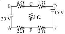
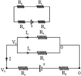
The figure shows a network of five resistances and two batteries. The total electrical power consumed by the circuit is ............... $W$.
A
$15$
B
$75$
C
$105$
D
$90$
Solution
(C) Let the potential at node $F$ be $0 \ V$. Then the potential at node $C$ is $V_C$. Applying Kirchhoff's Current Law $(KCL)$ at node $C$:
$\frac{V_C - 30}{4 + 2} + \frac{V_C - 0}{3} + \frac{V_C - 15}{1 + 2} = 0$
$\frac{V_C - 30}{6} + \frac{V_C}{3} + \frac{V_C - 15}{3} = 0$
Multiplying by $6$:
$(V_C - 30) + 2V_C + 2(V_C - 15) = 0$
$V_C - 30 + 2V_C + 2V_C - 30 = 0$
$5V_C = 60 \implies V_C = 12 \ V$.
The current in the left branch is $I_1 = \frac{30 - 12}{6} = 3 \ A$.
The current in the middle branch is $I_2 = \frac{12 - 0}{3} = 4 \ A$.
The current in the right branch is $I_3 = \frac{12 - 15}{3} = -1 \ A$ (meaning current flows from $D$ to $C$).
The power consumed by the circuit is the sum of power dissipated in resistors: $P = I_1^2 R_1 + I_2^2 R_2 + I_3^2 R_3$
$P = (3^2 \times 6) + (4^2 \times 3) + ((-1)^2 \times 3) = 54 + 48 + 3 = 105 \ W$.
0 likes
View Solution156
DifficultMCQ
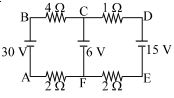
The figure shows a network of four resistances and three batteries. The electrical power dissipated as heat in the circuit is .............. $W$.
A
$207$
B
$123$
C
$165$
D
none
Solution
(B) Let the potential at node $F$ be $0 \ V$. Let the potential at node $C$ be $V_C$. Applying Kirchhoff's Current Law $(KCL)$ at node $C$:
$\frac{V_C - 30}{4 + 2} + \frac{V_C - 6}{0} + \frac{V_C - 15}{1 + 2} = 0$ (Note: The middle branch has only a battery,so $V_C = 6 \ V$).
If $V_C = 6 \ V$,the current in the left loop $(I_1)$ is: $I_1 = \frac{30 - 6}{4 + 2} = \frac{24}{6} = 4 \ A$.
The current in the right loop $(I_2)$ is: $I_2 = \frac{15 - 6}{1 + 2} = \frac{9}{3} = 3 \ A$.
The power dissipated in the resistances is $P = I_1^2 R_{left} + I_2^2 R_{right}$.
$P = (4)^2 \times (4 + 2) + (3)^2 \times (1 + 2) = 16 \times 6 + 9 \times 3 = 96 + 27 = 123 \ W$.
0 likes
View Solution157
MediumMCQ
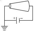
$A$ battery of $emf$ $E$ is being charged from a charger such that the positive terminal of the battery is connected to terminal $A$ of the charger and the negative terminal of the battery is connected to terminal $B$ of the charger. The internal resistance of the battery is $r$.
A
Potential difference across points $A$ and $B$ must be more than $E$.
B
$A$ must be at a higher potential than $B$.
C
In the battery,current flows from the positive terminal to the negative terminal.
D
All of the above.
Solution
(D) When a battery of $emf$ $E$ and internal resistance $r$ is being charged,the current $I$ flows into the positive terminal of the battery.
The terminal potential difference $V$ across the battery is given by the equation: $V = E + Ir$.
Since $I > 0$ and $r > 0$,it follows that $V > E$. Thus,the potential difference across the charger terminals $A$ and $B$ must be greater than $E$.
Because the positive terminal of the battery is connected to $A$ and the negative terminal to $B$,and current flows from $A$ to $B$ through the battery,$A$ must be at a higher potential than $B$.
Inside the battery during charging,the current flows from the positive terminal to the negative terminal.
Therefore,all the given statements are correct.
0 likes
View Solution158
MediumMCQ
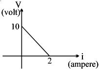
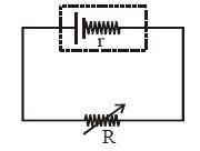
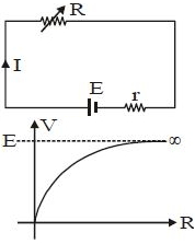
$A$ battery of $emf$ $E$ and internal resistance $r$ is connected across a resistance $R$. Resistance $R$ can be adjusted to any value greater than or equal to zero. $A$ graph is plotted between the current $(i)$ passing through the resistance and potential difference $(V)$ across it. Select the correct alternative$(s)$.
A
Internal resistance of the battery is $5\,\Omega$.
B
Emf of the battery is $20\,V$.
C
Maximum current which can be taken from the battery is $2\,A$.
D
$V-i$ graph can never be a straight line as shown in figure.
Solution
(A) The potential difference $V$ across a battery is given by the equation $V = E - ir$.
Comparing this with the equation of a straight line $y = mx + c$,we get $V = -ri + E$.
From the given graph,the intercept on the $V$-axis is $E = 10\,V$.
The intercept on the $i$-axis is the short-circuit current when $V = 0$,which is $i_{max} = E/r = 2\,A$.
Substituting $E = 10\,V$ and $i_{max} = 2\,A$,we get $r = E / i_{max} = 10 / 2 = 5\,\Omega$.
Thus,the internal resistance $r = 5\,\Omega$,the $emf$ $E = 10\,V$,and the maximum current is $2\,A$.
Comparing these with the options,option $A$ is correct.
0 likes
View Solution159
DifficultMCQ
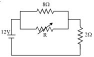
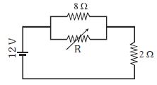
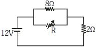
The value of the resistance $R$ in the figure is adjusted such that the power dissipated in the $2\,\Omega$ resistor is maximum. Under this condition:
A
$R = 0$
B
$R = 8\,\Omega$
C
power dissipated in the $2\,\Omega$ resistor is $72\,W$.
D
Both $(A)$ and $(C)$
Solution
(D) Let the voltage of the battery be $V = 12\,V$. The resistor $R$ and the $8\,\Omega$ resistor are in parallel. Let their equivalent resistance be $R_p = \frac{8R}{8+R}$.
This combination is in series with the $2\,\Omega$ resistor.
The total resistance of the circuit is $R_{eq} = R_p + 2 = \frac{8R}{8+R} + 2 = \frac{8R + 16 + 2R}{8+R} = \frac{10R + 16}{8+R}$.
The total current in the circuit is $I = \frac{V}{R_{eq}} = \frac{12(8+R)}{10R+16} = \frac{6(8+R)}{5R+8}$.
The power dissipated in the $2\,\Omega$ resistor is $P = I^2 \times 2 = 2 \times \left[ \frac{6(8+R)}{5R+8} \right]^2 = 72 \times \frac{(8+R)^2}{(5R+8)^2}$.
To maximize $P$,we analyze the function $f(R) = \frac{8+R}{5R+8}$.
As $R \to 0$,$f(R) \to \frac{8}{8} = 1$. As $R \to \infty$,$f(R) \to \frac{1}{5} = 0.2$.
Since $f(R)$ is a decreasing function for $R \ge 0$,the maximum value occurs at $R = 0$.
At $R = 0$,$P = 72 \times \left( \frac{8+0}{0+8} \right)^2 = 72 \times 1^2 = 72\,W$.
Thus,both $(A)$ and $(C)$ are correct.
0 likes
View Solution160
DifficultMCQ
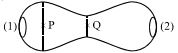
$A$ metallic conductor of irregular cross-section is as shown in the figure. $A$ constant potential difference is applied across the ends $(1)$ and $(2)$. Then:
A
the current at the cross-section $P$ equals the current at the cross-section $Q$
B
the electric field intensity at $P$ is less than that at $Q$
C
the rate of heat generated per unit time at $Q$ is greater than that at $P$
D
All of the above
Solution
(D) $1$. Since the conductor is in a steady state,the current $I$ flowing through any cross-section must be the same. Therefore,$I_P = I_Q$.
$2$. Current density $J = I/A$. Since the area $A_P > A_Q$,the current density $J_P < J_Q$. From Ohm's law in microscopic form,$J = \sigma E$,where $\sigma$ is conductivity. Thus,$E_P < E_Q$.
$3$. The rate of heat generated per unit time is power $H = I^2 R$. For a small segment of length $dx$,$dR = \rho \frac{dx}{A}$. Since $A_P > A_Q$,the resistance $R_Q > R_P$. Therefore,$H_Q > H_P$.
$4$. All statements are correct.
0 likes
View Solution161
DifficultMCQ
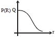
$A$ conductor is made of an isotropic material and has the shape of a truncated cone. $A$ battery of constant emf is connected across it and its left end is earthed as shown in the figure. If at a section distant $x$ from the left end, electric field intensity, potential, and the rate of generation of heat per unit length are $E, V$, and $H$ respectively, which of the following graphs is/are correct?
A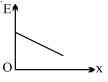
B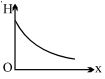
C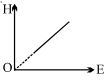
D
Both $(B)$ and $(C)$
Solution
(D) For a conductor of non-uniform cross-section, the current $I$ is constant throughout the length. The current density $J = I/A(x)$, where $A(x)$ is the cross-sectional area at distance $x$. Since the radius $r(x)$ increases with $x$, $A(x)$ increases, so $J$ decreases as $x$ increases. The electric field $E = \rho J = \rho I / A(x)$. Since $A(x)$ increases with $x$, $E$ decreases as $x$ increases. Thus, the graph of $E$ vs $x$ is a decreasing curve, not a straight line as shown in the provided image.
The rate of heat generation per unit length is $H = I^2 R_{unit} = I^2 (\rho / A(x))$. Since $A(x)$ increases with $x$, $H$ decreases as $x$ increases. The graph of $H$ vs $x$ is a decreasing curve.
Also, $H = I^2 \rho / A(x)$ and $E = I \rho / A(x)$. Therefore, $H = I E$. This implies that $H$ is directly proportional to $E$ $(H \propto E)$. Thus, the graph of $H$ vs $E$ is a straight line passing through the origin.
Comparing these with the provided options, graph $(C)$ is correct. Graph $(B)$ shows a decreasing curve for $H$ vs $x$, which is qualitatively correct for a truncated cone.
0 likes
View Solution162
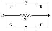
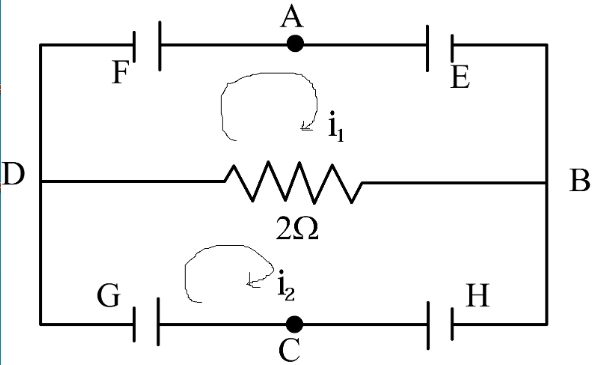
AdvancedMCQ
In the circuit shown,$E, F, G$,and $H$ are cells of e.m.f. $2\,V, 1\,V, 3\,V$,and $1\,V$ respectively,and their internal resistances are $2\,\Omega, 1\,\Omega, 3\,\Omega$,and $1\,\Omega$ respectively.
A
$V_D - V_B = - 2/13\, V$
B
$V_H = 19/13\, V =$ potential difference across $H$.
C
$V_G = 21/13\, V =$ potential difference across $G$.
D
All of the above
Solution
(D) Applying Kirchhoff's voltage law to the loops:
For loop $AFDBEA$ (assuming current $i_1$ clockwise):
$E_F - E_E = i_1(r_F + r_E + R) - R i_2$
$1 - 2 = i_1(1 + 2 + 2) - 2 i_2 \Rightarrow 5 i_1 - 2 i_2 = -1 \dots(1)$
For loop $CGDBHC$ (assuming current $i_2$ clockwise):
$E_H - E_G = i_2(r_H + r_G + R) - R i_1$
$1 - 3 = i_2(1 + 3 + 2) - 2 i_1 \Rightarrow -2 i_1 + 6 i_2 = -2 \dots(2)$
Multiplying $(1)$ by $3$: $15 i_1 - 6 i_2 = -3 \dots(3)$
Adding $(2)$ and $(3)$: $13 i_1 = -5 \Rightarrow i_1 = -5/13\, A$
Substituting $i_1$ in $(1)$: $5(-5/13) - 2 i_2 = -1 \Rightarrow -25/13 + 1 = 2 i_2 \Rightarrow i_2 = -6/13\, A$
Potential difference $V_D - V_B = R(i_2 - i_1) = 2(-6/13 - (-5/13)) = 2(-1/13) = -2/13\, V$.
Potential difference across $G$: $V_G = E_G + i_2 r_G = 3 + (-6/13)(3) = 3 - 18/13 = 21/13\, V$.
Potential difference across $H$: $V_H = E_H - i_2 r_H = 1 - (-6/13)(1) = 1 + 6/13 = 19/13\, V$.
0 likes
View Solution163
AdvancedMCQ
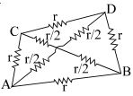
The figure shows a tetrahedron,each side of which has a resistance $r$. Choose the correct diagram$(s)$,which show a two-dimensional equivalent of the tetrahedron.
A
B
C
D
All of the above
Solution
(D) tetrahedron has $4$ vertices and $6$ edges. Let the vertices be $A, B, C, D$. Each edge has a resistance $r$.
To find the equivalent resistance between any two points,say $A$ and $B$,we can redraw the circuit.
The path $A-B$ is a direct edge with resistance $r$.
The path $A-C-B$ consists of two edges in series,each of resistance $r$,giving a total of $2r$.
The path $A-D-B$ also consists of two edges in series,each of resistance $r$,giving a total of $2r$.
Thus,the circuit between $A$ and $B$ consists of three parallel branches: one with resistance $r$,one with $2r$,and one with $2r$.
All the provided diagrams represent different ways to visualize or simplify this network,and they are all topologically equivalent representations of the same electrical circuit.
Therefore,all the diagrams are correct.
0 likes
View Solution164
MediumMCQ
$A$ thermocouple is made from two metals,Antimony and Bismuth. If one junction of the couple is kept hot and the other is kept cold,then,an electric current will
A
flow from Antimony to Bismuth at the cold junction
B
flow from Antimony to Bismuth at the hot junction
C
flow from Bismuth to Antimony at the cold junction
D
no flow through the thermocouple
Solution
(A) In a thermoelectric series,the direction of current flow at the cold junction is from the metal that appears later in the series to the metal that appears earlier.
For an Antimony-Bismuth thermocouple,the thermoelectric series order is Bismuth followed by Antimony.
Therefore,at the cold junction,the current flows from Antimony to Bismuth.
This creates a continuous loop where the current flows from Bismuth to Antimony at the hot junction.
For an Antimony-Bismuth thermocouple,the thermoelectric series order is Bismuth followed by Antimony.
Therefore,at the cold junction,the current flows from Antimony to Bismuth.
This creates a continuous loop where the current flows from Bismuth to Antimony at the hot junction.
0 likes
View Solution165
DifficultMCQ
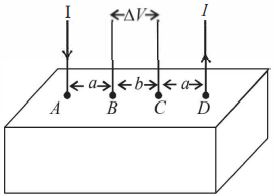
Consider a block of conducting material of resistivity $\rho$ shown in the figure. Current $I$ enters at $A$ and leaves from $D$. We apply the superposition principle to find the voltage $\Delta V$ developed between $B$ and $C$. The calculation is done in the following steps: $(i)$ Take current $I$ entering from $A$ and assume it to spread over a hemispherical surface in the block. $(ii)$ Calculate the field $E(r)$ at distance $r$ from $A$ by using Ohm's law $E=\rho j$,where $j$ is the current per unit area at $r$. $(iii)$ From the $r$ dependence of $E(r)$,obtain the potential $V(r)$ at $r$. $(iv)$ Repeat $(i), (ii)$ and $(iii)$ for current $I$ leaving $D$ and superpose results for $A$ and $D$. $\Delta V$ measured between $B$ and $C$ is
A
$\frac{\rho I}{2 \pi(a-b)}$
B
$\frac{\rho I}{\pi a}-\frac{\rho I}{\pi(a+b)}$
C
$\frac{\rho I}{a}-\frac{\rho I}{(a+b)}$
D
$\frac{\rho I}{2 \pi a}-\frac{\rho I}{2 \pi(a+b)}$
Solution
(B) Let $j$ be the current density.
Since the current $I$ spreads over a hemispherical surface,$j \times 2 \pi r^2 = I$,which gives $j = \frac{I}{2 \pi r^2}$.
Using Ohm's law,the electric field is $E = \rho j = \frac{\rho I}{2 \pi r^2}$.
The potential difference due to current $I$ entering at $A$ between points $B$ and $C$ is $\Delta V_{BC, A} = V_B - V_C = \int_{r_B}^{r_C} E dr = \int_{a}^{a+b} \frac{\rho I}{2 \pi r^2} dr = \frac{\rho I}{2 \pi} \left[ -\frac{1}{r} \right]_{a}^{a+b} = \frac{\rho I}{2 \pi} \left( \frac{1}{a} - \frac{1}{a+b} \right)$.
Similarly,for current $I$ leaving at $D$,the potential difference $\Delta V_{BC, D}$ is also $\frac{\rho I}{2 \pi} \left( \frac{1}{a} - \frac{1}{a+b} \right)$.
By the superposition principle,the total potential difference is $\Delta V = \Delta V_{BC, A} + \Delta V_{BC, D} = 2 \times \frac{\rho I}{2 \pi} \left( \frac{1}{a} - \frac{1}{a+b} \right) = \frac{\rho I}{\pi a} - \frac{\rho I}{\pi(a+b)}$.
0 likes
View Solution166
DifficultMCQ
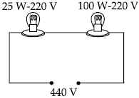
Two electric bulbs marked $25\ W - 220\ V$ and $100\ W - 220\ V$ are connected in series to a $440\ V$ supply. Which of the bulbs will fuse?
A
Neither
B
Both
C
$100\ W$
D
$25\ W$
Solution
(D) First,calculate the resistance of each bulb using $R = V^2 / P$:
$R_1 = (220)^2 / 25 = 1936\ \Omega$
$R_2 = (220)^2 / 100 = 484\ \Omega$
The total resistance in series is $R_{eff} = R_1 + R_2 = 1936 + 484 = 2420\ \Omega$.
The current flowing through the series circuit is $I = V_{supply} / R_{eff} = 440 / 2420 = 44 / 242 = 2 / 11\ A \approx 0.1818\ A$.
Now,calculate the maximum rated current for each bulb using $I_{rated} = P / V$:
For the $25\ W$ bulb: $I_{1,rated} = 25 / 220 = 5 / 44 \approx 0.1136\ A$.
For the $100\ W$ bulb: $I_{2,rated} = 100 / 220 = 5 / 11 \approx 0.4545\ A$.
Comparing the circuit current $I$ with the rated currents:
Since $I (0.1818\ A) > I_{1,rated} (0.1136\ A)$,the $25\ W$ bulb will fuse.
Since $I (0.1818\ A) < I_{2,rated} (0.4545\ A)$,the $100\ W$ bulb will not fuse.
0 likes
View Solution167
MediumMCQ
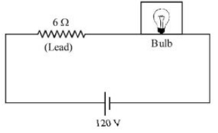
The supply voltage to a room is $120\ V$. The resistance of the lead wires is $6\,\Omega$. $A$ $60\ W$ bulb is already switched on. What is the decrease in voltage across the bulb when a $240\ W$ heater is switched on in parallel to the bulb? ............. $V$
A
$10.4$
B
$0$
C
$2.9$
D
$13.3$
Solution
(A) Power of bulb $P_b = 60\, W$. Resistance of bulb $R_b = \frac{V^2}{P_b} = \frac{120^2}{60} = 240\,\Omega$.
Resistance of lead wires $R_L = 6\,\Omega$.
Voltage across bulb before heater is switched on: $V_1 = \frac{R_b}{R_b + R_L} \times 120 = \frac{240}{240 + 6} \times 120 = \frac{240}{246} \times 120 \approx 117.07\, V$.
Power of heater $P_h = 240\, W$. Resistance of heater $R_h = \frac{V^2}{P_h} = \frac{120^2}{240} = 60\,\Omega$.
When heater is in parallel with bulb,equivalent resistance $R_p = \frac{R_b \times R_h}{R_b + R_h} = \frac{240 \times 60}{240 + 60} = \frac{14400}{300} = 48\,\Omega$.
Voltage across bulb after heater is switched on: $V_2 = \frac{R_p}{R_p + R_L} \times 120 = \frac{48}{48 + 6} \times 120 = \frac{48}{54} \times 120 \approx 106.67\, V$.
Decrease in voltage $= V_1 - V_2 = 117.07 - 106.67 = 10.4\, V$.
0 likes
View Solution168
EasyMCQ
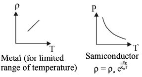
The temperature dependence of resistances of $Cu$ and undoped $Si$ in the temperature range $300-400 \ K$,is best described by
A
Linear increase for $Cu$,exponential decrease of $Si$
B
Linear decrease for $Cu$,linear decrease for $Si$
C
Linear increase for $Cu$,linear increase for $Si$
D
Linear increase for $Cu$,exponential increase for $Si$
Solution
(A) For a metal like $Cu$,the resistance $R$ increases linearly with temperature $T$ in a limited range,given by $R = R_0(1 + \alpha \Delta T)$,where $\alpha$ is the temperature coefficient of resistance.
For an intrinsic (undoped) semiconductor like $Si$,the number of charge carriers increases exponentially with temperature,leading to an exponential decrease in resistance,given by $\rho = \rho_0 e^{E_g / k_B T}$,where $E_g$ is the band gap energy and $k_B$ is the Boltzmann constant.
For an intrinsic (undoped) semiconductor like $Si$,the number of charge carriers increases exponentially with temperature,leading to an exponential decrease in resistance,given by $\rho = \rho_0 e^{E_g / k_B T}$,where $E_g$ is the band gap energy and $k_B$ is the Boltzmann constant.
0 likes
View Solution169
AdvancedMCQ
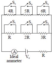
Suppose switches $S_1, S_2$ and so on up to $S_6$ are closed one after another in order (first $S_1$,then $S_2$,etc.) at regular intervals of $1 \text{ minute}$ starting from $t = 0$. The graph of current versus time is best represented as:
A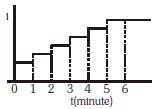
B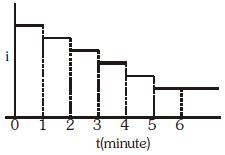
C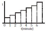
D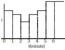
Solution
(A) The circuit consists of a battery $V_0$ in series with a resistor $R$ and a parallel combination of resistors. Initially,all switches are open. When a switch $S_n$ is closed,it short-circuits the corresponding resistor $nR$.
As switches $S_1, S_2, \dots, S_6$ are closed sequentially at $1 \text{ minute}$ intervals,the total resistance of the circuit decreases.
According to Ohm's law,$I = V/R_{eq}$. Since the total resistance $R_{eq}$ decreases with each step,the current $I$ must increase at each step.
Comparing this with the given options,the graph that shows a step-wise increase in current over time is Graph $A$.
0 likes
View Solution170
MediumMCQ
Which of the following graphs represents the variation of power loss in the external load with external resistance $R$?
A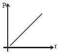
B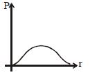
C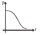
D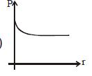
Solution
(B) The power $P$ dissipated in an external resistance $R$ connected to a cell of electromotive force $E$ and internal resistance $r$ is given by the formula:
$P = I^2 R$
Since the current $I = \frac{E}{R+r}$,we have:
$P = \left( \frac{E}{R+r} \right)^2 R = \frac{E^2 R}{(R+r)^2}$
To find the variation of $P$ with $R$,we analyze the function $P(R) = \frac{E^2 R}{(R+r)^2}$.
$1$. When $R = 0$,$P = 0$.
$2$. When $R \to \infty$,$P \to 0$.
$3$. The maximum power is dissipated when $R = r$,where $P_{max} = \frac{E^2}{4r}$.
This behavior corresponds to a curve that starts from the origin,increases to a maximum value at $R = r$,and then decreases asymptotically towards zero as $R$ increases further. This matches the shape of Graph $B$.
0 likes
View Solution171
DifficultMCQ
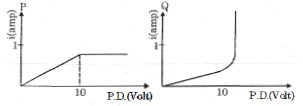
Two current elements $P$ and $Q$ have current-voltage characteristics as shown below. Which of the graphs given below best represents the current-voltage characteristics when $P$ and $Q$ are in series?
A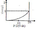
B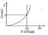
C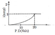
D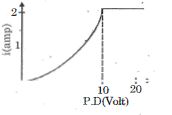
Solution
(A) When two elements $P$ and $Q$ are connected in series,the current $i$ flowing through both is the same,and the total potential difference $V$ across the combination is the sum of the potential differences across each element: $V = V_P + V_Q$.
From the given graphs,for element $P$,the current $i$ increases linearly with $V_P$ up to $10 \text{ V}$ (where $i = 1 \text{ A}$) and remains constant at $1 \text{ A}$ for $V_P > 10 \text{ V}$.
For element $Q$,the current $i$ increases with $V_Q$ and reaches $1 \text{ A}$ at $V_Q = 10 \text{ V}$.
When in series,for a given current $i$ (where $0 \le i \le 1 \text{ A}$),the total voltage $V$ is $V_P(i) + V_Q(i)$.
At $i = 0$,$V = 0 + 0 = 0 \text{ V}$.
At $i = 1 \text{ A}$,$V = 10 \text{ V} + 10 \text{ V} = 20 \text{ V}$.
Since $V_P$ is linear and $V_Q$ is non-linear (curved),the sum $V = V_P + V_Q$ will also be a curve that reaches $20 \text{ V}$ at $i = 1 \text{ A}$.
For $i > 1 \text{ A}$,element $P$ cannot conduct more than $1 \text{ A}$,so the series combination cannot conduct more than $1 \text{ A}$.
Thus,the graph must show a curve ending at $i = 1 \text{ A}$ and $V = 20 \text{ V}$,followed by a vertical line at $V = 20 \text{ V}$ for $i > 1 \text{ A}$. This corresponds to Graph $A$.
0 likes
View Solution172
AdvancedMCQ
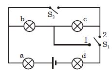
Four lamps are connected as shown in the figure. When switch $S_2$ is open and switch $S_1$ is at position $2$,lamp $b$ is the brightest,and lamps $c$ and $d$ are the dimmest and have the same brightness. Now,if $S_2$ is closed and $S_1$ is at position $1$,what is the sequence of brightness of the lamps (starting from the brightest)?
A
$c, d, b, a$
B
$a, d, b, c$
C
$a, b, c, d$
D
$a, d, c, b$
Solution
(D) When $S_2$ is open and $S_1$ is at position $2$,the circuit is a series combination of $a, b, c, d$. Since $P = I^2 R$,and $b$ is brightest,$R_b$ is the largest. Since $c$ and $d$ are dimmest and equal,$R_c = R_d$. Given the series circuit,$P_b > P_a > P_c = P_d$,which implies $R_b > R_a > R_c = R_d$.
When $S_2$ is closed and $S_1$ is at position $1$,the circuit configuration changes. Lamps $b$ and $c$ are now in parallel,and this combination is in series with $a$ and $d$. Let the voltage across the parallel combination be $V_0$. Then $P'_b = V_0^2 / R_b$ and $P'_c = V_0^2 / R_c$. Since $R_b > R_c$,we have $P'_c > P'_b$.
For lamps $a$ and $d$,they carry the total current $I$. Since $R_a > R_d$,$P'_a = I^2 R_a > P'_d = I^2 R_d$.
Comparing the parallel branch with the series components,the power in the parallel branch is $P'_c = I_2^2 R_c = [I (R_b / (R_b + R_c))]^2 R_c$. Since $R_b > R_c$,the effective resistance of the parallel part is less than $R_d$,leading to $P'_a > P'_d > P'_c > P'_b$.
0 likes
View Solution173
MediumMCQ
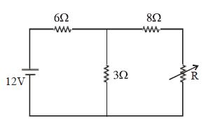
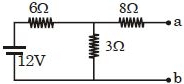
The maximum power delivered to resistance $R$ is ............... $W$.
A
$0.2$
B
$0.4$
C
$0.8$
D
$0.16$
Solution
(B) To find the maximum power delivered to the variable resistance $R$, we use the Maximum Power Transfer Theorem. According to this theorem, the power is maximum when $R = R_{th}$, where $R_{th}$ is the Thevenin equivalent resistance across the terminals of $R$.
$1$. Find the Thevenin voltage ($V_{th}$ or $V_{ab}$): Remove $R$ and calculate the open-circuit voltage across the terminals $a$ and $b$. The $6 \, \Omega$ and $3 \, \Omega$ resistors form a voltage divider across the $12 \, V$ source. The voltage across the $3 \, \Omega$ resistor is $V_{ab} = 12 \times \frac{3}{6+3} = 12 \times \frac{3}{9} = 4 \, V$.
$2$. Find the Thevenin resistance ($R_{th}$ or $R_{ab}$): Short the voltage source. The $6 \, \Omega$ and $3 \, \Omega$ resistors are now in parallel, and this combination is in series with the $8 \, \Omega$ resistor. Thus, $R_{ab} = 8 + \frac{6 \times 3}{6+3} = 8 + \frac{18}{9} = 8 + 2 = 10 \, \Omega$.
$3$. Calculate maximum power: $P_{\max} = \frac{V_{ab}^2}{4 R_{ab}} = \frac{4^2}{4 \times 10} = \frac{16}{40} = 0.4 \, W$.
0 likes
View Solution174
MediumMCQ
Two cables of copper are of equal lengths. One of them has a single wire of area of cross-section $A$, while the other has $10$ wires of cross-sectional area $A / 10$ each. Determine their suitability for transporting $A.C.$ and $D.C.$
A
Only single strand for $A.C.$, either for $D.C.$
B
Only single strand for $D.C.$, either for $A.C.$
C
Only multiple strands for $A.C.$, only single strand for $D.C.$
D
Only multiple strands for $A.C.$, either for $D.C.$
Solution
(D) The phenomenon known as the $Skin \text{ } Effect$ causes the majority of $A.C.$ current to flow near the surface of a conductor.
For $A.C.$ transmission, using a single thick wire is inefficient because the interior of the wire carries very little current.
By using multiple thin strands, the total surface area is increased, which reduces the effective resistance for $A.C.$ and improves efficiency.
For $D.C.$ transmission, the current is distributed uniformly throughout the cross-section of the conductor, so either a single thick wire or multiple thin strands will function effectively.
Therefore, multiple strands are preferred for $A.C.$, while either type is suitable for $D.C.$
0 likes
View Solution175
DifficultMCQ
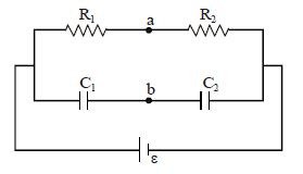
Two resistors with resistances $R_1$ and $R_2$ are connected in series and two capacitors with capacitances $C_1$ and $C_2$ are also connected in series. These two systems are connected to a battery of $EMF$ $\varepsilon$ as shown in the figure. The potential difference between points $a$ and $b$ is zero in the steady state if:
A
$R_1 + R_2 = \frac{C_1 C_2}{C_1 + C_2}$
B
$R_1 R_2 = C_1 C_2$
C
$R_1 C_2 = R_2 C_1$
D
$R_1 C_1 = R_2 C_2$
Solution
(D) In the steady state,the capacitors act as open circuits,so no current flows through the capacitor branch. The potential at point $a$ relative to the negative terminal of the battery is determined by the voltage divider rule for resistors: $V_a = \frac{\varepsilon R_2}{R_1 + R_2}$.
Similarly,the potential at point $b$ relative to the negative terminal is determined by the voltage divider rule for capacitors: $V_b = \frac{\varepsilon C_1}{C_1 + C_2}$.
For the potential difference between $a$ and $b$ to be zero,we must have $V_a = V_b$.
Therefore,$\frac{\varepsilon R_2}{R_1 + R_2} = \frac{\varepsilon C_1}{C_1 + C_2}$.
Simplifying this,$R_2(C_1 + C_2) = C_1(R_1 + R_2)$.
$R_2 C_1 + R_2 C_2 = C_1 R_1 + C_1 R_2$.
$R_2 C_2 = R_1 C_1$.
0 likes
View Solution176
MediumMCQ
$A$ cell of emf $E$ has an internal resistance $r$ and is connected to a rheostat. When the resistance $R$ of the rheostat is changed,which is the correct graph of the potential difference $V$ across it?
A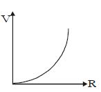
B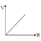
C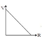
D
Solution
(D) The potential difference $V$ across the rheostat of resistance $R$ is given by the formula:
$V = IR = \left( \frac{E}{R+r} \right) R = \frac{E}{1 + \frac{r}{R}}$
Analyzing the behavior of $V$ with respect to $R$:
$1$. When $R = 0$,$V = 0$.
$2$. As $R$ increases,the term $\frac{r}{R}$ decreases,so $V$ increases.
$3$. As $R \to \infty$,the term $\frac{r}{R} \to 0$,so $V \to E$.
The graph starts from the origin $(0,0)$ and asymptotically approaches the value $E$ as $R$ increases. This corresponds to an upward convex curve. Thus,the correct graph is shown in option $D$.
0 likes
View Solution177
DifficultMCQ
Suppose the drift velocity $v_d$ in a material varies with the applied electric field $E$ as $v_d \propto \sqrt{E}$. Then the $V-I$ graph for a wire made of such a material is best given by:
A
B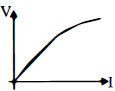
C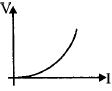
D
Solution
(C) The current $I$ is related to the drift velocity $v_d$ by the formula $I = n e A v_d$,where $n$ is the charge carrier density,$e$ is the charge,and $A$ is the cross-sectional area.
Given that $v_d \propto \sqrt{E}$,we can substitute this into the current equation:
$I \propto v_d \propto \sqrt{E}$
Since the electric field $E$ is related to the potential difference $V$ across a wire of length $L$ by $E = V/L$,we have $E \propto V$.
Substituting this into the proportionality for current:
$I \propto \sqrt{V}$
Squaring both sides,we get:
$I^2 \propto V$
This represents a parabolic relationship where $V$ is proportional to the square of $I$ $(V = k I^2)$. This corresponds to a curve that is concave up,starting from the origin. Among the given options,the graph that shows $V$ increasing more rapidly than $I$ (a parabolic curve opening upwards) is the correct one.
0 likes
View Solution178
DifficultMCQ
This question has Statement $1$ and Statement $2.$ Of the four choices given after the Statements,choose the one that best describes the two Statements.
Statement $1 :$ The possibility of an electric bulb fusing is higher at the time of switching $ON.$
Statement $2:$ Resistance of an electric bulb when it is not lit up is much smaller than when it is lit up.
Statement $1 :$ The possibility of an electric bulb fusing is higher at the time of switching $ON.$
Statement $2:$ Resistance of an electric bulb when it is not lit up is much smaller than when it is lit up.
A
Statement $1$ is true,Statement $2$ is false.
B
Statement $1$ is false,Statement $2$ is true,Statement $2$ is not a correct explanation of Statement $1$.
C
Statement $1$ is true,Statement $2$ is true,Statement $2$ is a correct explanation of Statement $1$.
D
Statement $1$ is false,Statement $2$ is true.
Solution
(C) The resistance of a metallic filament (like tungsten) increases with temperature. When the bulb is switched $ON$,the filament is at room temperature,so its resistance is very low. According to Ohm's law,$I = V/R$,a very high surge current flows through the filament initially. This high current causes a sudden thermal shock and mechanical stress,which increases the probability of the filament breaking (fusing). As the bulb heats up,the resistance increases,and the current stabilizes to its rated value. Thus,both statements are true,and Statement $2$ is the correct explanation for Statement $1$.
0 likes
View Solution179
MediumMCQ
The value of the resistance $R$ in the figure is adjusted such that the power dissipated in the $2\,\Omega$ resistor is maximum. Then the power dissipated in the $2\,\Omega$ resistor will be ................ $W$.
A
$72$
B
$40$
C
$8$
D
$32$
Solution
(A) The circuit consists of a $12\,V$ voltage source in series with a parallel combination of an $8\,\Omega$ resistor and a variable resistor $R$,which is then in series with a $2\,\Omega$ resistor.
Let $R_p$ be the equivalent resistance of the parallel combination of $8\,\Omega$ and $R$,given by $R_p = \frac{8R}{8+R}$.
The total resistance of the circuit is $R_{eq} = R_p + 2 = \frac{8R}{8+R} + 2$.
The current $I$ flowing through the $2\,\Omega$ resistor is $I = \frac{V}{R_{eq}} = \frac{12}{\frac{8R}{8+R} + 2} = \frac{12(8+R)}{8R + 16 + 2R} = \frac{12(8+R)}{10R + 16}$.
The power dissipated in the $2\,\Omega$ resistor is $P = I^2 \times 2 = 2 \times \left[ \frac{12(8+R)}{10R + 16} \right]^2$.
To maximize $P$,we need to maximize the current $I$. The current $I$ is maximum when the total resistance $R_{eq}$ is minimum.
$R_{eq} = \frac{8R}{8+R} + 2$. Since $R$ is a resistance,$R \ge 0$. The function $f(R) = \frac{8R}{8+R}$ is an increasing function of $R$. Thus,$R_{eq}$ is minimum when $R = 0$.
When $R = 0$,the parallel combination becomes a short circuit,so $R_p = 0$.
The total resistance becomes $R_{eq} = 0 + 2 = 2\,\Omega$.
The current $I = \frac{12\,V}{2\,\Omega} = 6\,A$.
The power dissipated in the $2\,\Omega$ resistor is $P = I^2 R_{fixed} = (6)^2 \times 2 = 36 \times 2 = 72\,W$.
0 likes
View Solution180
MediumMCQ
Two electric bulbs marked $40\,W, 220\,V$ and $60\,W, 220\,V$ are connected in series across a $220\,V$ supply,resulting in an effective power $P_1$. When they are connected in parallel across the same $220\,V$ supply,the effective power is $P_2$. The ratio $\frac{P_1}{P_2}$ is:
A
$0.5$
B
$0.48$
C
$0.24$
D
$0.16$
Solution
(C) The resistance of a bulb is given by $R = \frac{V^2}{P}$.
For the first bulb $(40\,W, 220\,V)$,$R_1 = \frac{220^2}{40} = 1210\,\Omega$.
For the second bulb $(60\,W, 220\,V)$,$R_2 = \frac{220^2}{60} = 806.67\,\Omega$.
When connected in series,the total resistance $R_s = R_1 + R_2 = \frac{220^2}{40} + \frac{220^2}{60} = 220^2 \left( \frac{3+2}{120} \right) = 220^2 \left( \frac{5}{120} \right) = \frac{220^2}{24}$.
The effective power in series is $P_1 = \frac{V^2}{R_s} = \frac{220^2}{220^2/24} = 24\,W$.
When connected in parallel,the effective power is $P_2 = P_1' + P_2' = 40\,W + 60\,W = 100\,W$.
Therefore,the ratio $\frac{P_1}{P_2} = \frac{24}{100} = 0.24$.
0 likes
View Solution181
DifficultMCQ
The charge flowing through a resistance $R$ varies with time according to $Q = at - bt^2$. The total heat produced in $R$ is: (assume that the direction of current is not reversed)
A
$\frac{a^3R}{6b}$
B
$\frac{a^3R}{2b}$
C
$\frac{a^3R}{3b}$
D
$\frac{a^3R}{b}$
Solution
(A) Given the charge $Q = at - bt^2$.
The current $I$ is the rate of flow of charge: $I = \frac{dQ}{dt} = a - 2bt$.
The current becomes zero at time $t_0$ when $a - 2bt_0 = 0$,which gives $t_0 = \frac{a}{2b}$.
The heat produced $H$ in the resistance $R$ is given by $H = \int_0^{t_0} I^2 R \, dt$.
Substituting $I = a - 2bt$:
$H = \int_0^{a/2b} (a - 2bt)^2 R \, dt = R \int_0^{a/2b} (a^2 - 4abt + 4b^2t^2) \, dt$.
Integrating with respect to $t$:
$H = R \left[ a^2t - 2abt^2 + \frac{4b^2t^3}{3} \right]_0^{a/2b}$.
Substituting the upper limit $t = \frac{a}{2b}$:
$H = R \left[ a^2(\frac{a}{2b}) - 2ab(\frac{a^2}{4b^2}) + \frac{4b^2}{3}(\frac{a^3}{8b^3}) \right]$
$H = R \left[ \frac{a^3}{2b} - \frac{a^3}{2b} + \frac{a^3}{6b} \right] = \frac{a^3R}{6b}$.
0 likes
View Solution182
MediumMCQ
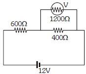
Find the percentage error in the reading of the voltmeter shown in the circuit. (in $\%$)
A
$16.67$
B
$8$
C
$4$
D
$5$
Solution
(A) Case $1$: When the resistance of the voltmeter is considered infinite (ideal voltmeter).
In this case,the voltmeter does not draw any current. The circuit consists of a $600 \, \Omega$ resistor and a $400 \, \Omega$ resistor in series connected to a $12 \, V$ source.
The voltage across the $400 \, \Omega$ resistor is given by the voltage divider rule:
$V_{1} = 12 \times \frac{400}{600 + 400} = 12 \times \frac{400}{1000} = 4.8 \, V$.
Case $2$: When the resistance of the voltmeter $(1200 \, \Omega)$ is taken into account.
The voltmeter is in parallel with the $400 \, \Omega$ resistor. The equivalent resistance of this parallel combination is:
$R_{p} = \frac{400 \times 1200}{400 + 1200} = \frac{480000}{1600} = 300 \, \Omega$.
Now,the circuit consists of a $600 \, \Omega$ resistor in series with the $300 \, \Omega$ equivalent resistance.
The voltage across the parallel combination (which is the voltmeter reading) is:
$V_{2} = 12 \times \frac{300}{600 + 300} = 12 \times \frac{300}{900} = 4 \, V$.
The percentage error is calculated as:
$\text{Error} = \frac{V_{1} - V_{2}}{V_{1}} \times 100 \% = \frac{4.8 - 4}{4.8} \times 100 \% = \frac{0.8}{4.8} \times 100 \% = \frac{1}{6} \times 100 \% = 16.67 \%$.
0 likes
View Solution183
DifficultMCQ
If the internal resistance of a cell is proportional to the current drawn from the cell,then the best representation of the terminal potential difference of the cell with respect to the current drawn from the cell will be:
A
B
C
D
Solution
(D) The terminal potential difference $V$ of a cell is given by the formula $V = E - Ir$,where $E$ is the electromotive force,$I$ is the current drawn,and $r$ is the internal resistance.
Given that the internal resistance $r$ is proportional to the current $I$,we can write $r = kI$,where $k$ is a positive constant.
Substituting this into the potential difference equation,we get $V = E - I(kI) = E - kI^2$.
This equation $V = E - kI^2$ represents a downward-opening parabola starting from $V = E$ at $I = 0$.
Comparing this with the given options,the graph in option $D$ represents a downward-opening curve starting from the $V$-axis,which matches the derived relationship.
0 likes
View Solution184
DifficultMCQ
Two electrical bulbs marked $40\, W, 220\, V$ and $60\, W, 220\, V$ are connected in series across a $220\, V$ supply. The effective power is $P_1$. When they are connected in parallel across the same supply, the effective power is $P_2$. The ratio $(P_1/P_2)$ is:
A
$0.5$
B
$0.48$
C
$0.24$
D
$0.16$
Solution
(C) The resistance of a bulb is given by $R = V^2 / P$.
For the first bulb, $R_1 = 220^2 / 40$.
For the second bulb, $R_2 = 220^2 / 60$.
When connected in series, the effective resistance is $R_s = R_1 + R_2$. The power consumed is $P_1 = V^2 / (R_1 + R_2)$.
When connected in parallel, the effective resistance is $R_p = (R_1 R_2) / (R_1 + R_2)$. The power consumed is $P_2 = V^2 / R_p = V^2 (R_1 + R_2) / (R_1 R_2)$.
The ratio is $P_1 / P_2 = [V^2 / (R_1 + R_2)] / [V^2 (R_1 + R_2) / (R_1 R_2)] = (R_1 R_2) / (R_1 + R_2)^2$.
Substituting the values: $R_1 = 1210\, \Omega$ and $R_2 = 806.67\, \Omega$.
$P_1 / P_2 = (40 \times 60) / (40 + 60)^2 = 2400 / 10000 = 0.24$.
0 likes
View Solution185
MediumMCQ
The rate of increase of thermo-e.m.f. with temperature at the neutral temperature of a thermocouple [$AIPMT$ $2011$]
A
is positive
B
is zero
C
is negative
D
depends upon the choice of the two materials of the thermocouple
Solution
(B) The thermo-e.m.f. $(E)$ in a thermocouple is given by the relation $E = \alpha \theta + \frac{1}{2} \beta \theta^2$,where $\theta$ is the temperature difference between the junctions.
At the neutral temperature $(\theta_n)$,the thermo-e.m.f. is maximum.
Mathematically,for the e.m.f. to be maximum,the first derivative of $E$ with respect to temperature must be zero.
Therefore,$\frac{dE}{d\theta} = 0$ at $\theta = \theta_n$.
This derivative $\frac{dE}{d\theta}$ represents the rate of increase of thermo-e.m.f. with temperature.
Thus,at the neutral temperature,the rate of increase of thermo-e.m.f. is zero.
0 likes
View Solution186
DifficultMCQ
The electrochemical equivalent of a substance is numerically equal to the mass of the substance deposited if a current $I$ flows through the electrolyte for $0.25\,s$. The value of $I$ is ................ $A$.
A
$1$
B
$2$
C
$3$
D
$4$
Solution
(D) According to Faraday's law of electrolysis,the mass $m$ of a substance deposited is given by $m = ZIt$,where $Z$ is the electrochemical equivalent,$I$ is the current,and $t$ is the time.
Given that the electrochemical equivalent $Z$ is numerically equal to the mass $m$ deposited,we have $m = Z$.
Substituting this into the equation: $Z = ZIt$.
Dividing both sides by $Z$ (assuming $Z \neq 0$),we get $1 = It$.
Given $t = 0.25\,s$,we have $1 = I \times 0.25$.
Therefore,$I = \frac{1}{0.25} = 4\,A$.
0 likes
View Solution187
MediumMCQ
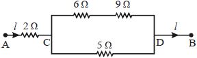
In the circuit shown in the figure,the $5\,\Omega$ resistance develops $20.00\,cal/s$ due to the current flowing through it. The heat developed in the $2\,\Omega$ resistance (in $cal/s$) is
A
$23.8$
B
$14.2$
C
$11.9$
D
$7.1$
Solution
(B) Let $I_1$ be the current through the $5\,\Omega$ resistance and $I_2$ be the current through the $(6+9)\,\Omega$ branch.
Given that the heat developed in the $5\,\Omega$ resistance is $20.00\,cal/s$,we have:
$P_1 = I_1^2 R_1 = 20.00\,cal/s$
$I_1^2 \times 5 = 20 \implies I_1^2 = 4 \implies I_1 = 2\,A$.
The potential difference across points $C$ and $D$ is $V_{CD} = I_1 \times 5 = 2 \times 5 = 10\,V$.
The current through the upper branch $(6\,\Omega + 9\,\Omega)$ is $I_2 = \frac{V_{CD}}{6+9} = \frac{10}{15} = \frac{2}{3}\,A$.
The total current $I$ flowing through the $2\,\Omega$ resistance is $I = I_1 + I_2 = 2 + \frac{2}{3} = \frac{8}{3}\,A$.
The heat developed per second in the $2\,\Omega$ resistance is $P = I^2 R = \left(\frac{8}{3}\right)^2 \times 2 = \frac{64}{9} \times 2 = \frac{128}{9} \approx 14.22\,cal/s$.
0 likes
View Solution188
MediumMCQ
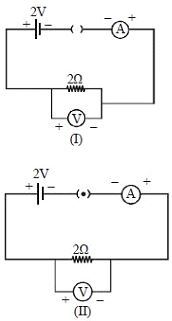
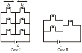
For the circuits shown in figures $I$ and $II$,the voltmeter reading would be
A
$2 \ V$ in circuit $I$ and $0 \ V$ in circuit $II$
B
$0 \ V$ in both circuits
C
$2 \ V$ in both circuits
D
$0 \ V$ in circuit $I$ and $2 \ V$ in circuit $II$
Solution
(D) In circuit $I$,the switch (key) is open,which means the circuit is incomplete. Therefore,no current flows through the resistor $(I = 0 \ A)$. According to Ohm's law,the voltage drop across the resistor is $V = I \times R = 0 \times 2 = 0 \ V$. Thus,the voltmeter reads $0 \ V$.
In circuit $II$,the switch is closed,completing the circuit. The current flows through the resistor. Since the internal resistance of the battery is not mentioned,we assume it to be ideal. The entire electromotive force $(2 \ V)$ appears across the $2 \ \Omega$ resistor. Therefore,the voltmeter reads $2 \ V$.
In circuit $II$,the switch is closed,completing the circuit. The current flows through the resistor. Since the internal resistance of the battery is not mentioned,we assume it to be ideal. The entire electromotive force $(2 \ V)$ appears across the $2 \ \Omega$ resistor. Therefore,the voltmeter reads $2 \ V$.
0 likes
View Solution189
EasyMCQ
Assertion: In a simple battery circuit,the point of the lowest potential is the positive terminal of the battery.
Reason: The current flows towards the point of the higher potential,as it does in such a circuit from the negative to the positive terminal.
Reason: The current flows towards the point of the higher potential,as it does in such a circuit from the negative to the positive terminal.
A
If both Assertion and Reason are correct and the Reason is a correct explanation of the Assertion.
B
If both Assertion and Reason are correct but Reason is not a correct explanation of the Assertion.
C
If the Assertion is correct but Reason is incorrect.
D
If both the Assertion and Reason are incorrect.
Solution
(D) The positive terminal of a battery is the point of the highest potential,not the lowest. Therefore,the Assertion is incorrect.
In an external circuit,current flows from the positive terminal (higher potential) to the negative terminal (lower potential). The Reason states that current flows towards the point of higher potential,which is also incorrect. Thus,both the Assertion and the Reason are incorrect.
In an external circuit,current flows from the positive terminal (higher potential) to the negative terminal (lower potential). The Reason states that current flows towards the point of higher potential,which is also incorrect. Thus,both the Assertion and the Reason are incorrect.
0 likes
View Solution190
EasyMCQ
Assertion : An electric bulb becomes dim,when the electric heater in parallel circuit is switched on.
Reason : Dimness decreases after sometime.
Reason : Dimness decreases after sometime.
A
If both Assertion and Reason are correct and the Reason is a correct explanation of the Assertion.
B
If both Assertion and Reason are correct but Reason is not a correct explanation of the Assertion.
C
If the Assertion is correct but Reason is incorrect.
D
If both the Assertion and Reason are incorrect.
Solution
(A) The electric power of a heater is significantly higher than that of a bulb. Since $P = V^2/R$,we have $R \propto 1/P$,meaning the resistance of the heater is much lower than that of the bulb.
When the heater is switched on in parallel,the total current drawn from the source increases. Due to the internal resistance of the source (or line resistance),the terminal voltage across the bulb drops,causing it to become dim.
As the heater coil heats up,its resistance increases due to the positive temperature coefficient of the material. Consequently,the current drawn by the heater decreases,the terminal voltage recovers,and the bulb's brightness increases (dimness decreases).
0 likes
View Solution191
EasyMCQ
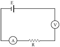
Assertion : All electric devices shown in the circuit are ideal. The reading of each of ammeter $(A)$ and voltmeter $(V)$ is zero.
Reason : An ideal voltmeter draws almost no current due to very large resistance, and hence $(V)$ and $(A)$ will read zero.
Reason : An ideal voltmeter draws almost no current due to very large resistance, and hence $(V)$ and $(A)$ will read zero.
A
If both Assertion and Reason are correct and Reason is the correct explanation of Assertion.
B
If both Assertion and Reason are correct, but Reason is not the correct explanation of Assertion.
C
If Assertion is correct but Reason is incorrect.
D
If both the Assertion and Reason are incorrect.
Solution
(D) In the given circuit, the battery $E$, ammeter $A$, resistor $R$, and voltmeter $V$ are connected in series.
An ideal voltmeter has infinite resistance, which prevents any current from flowing through the circuit.
Since the circuit is effectively open due to the infinite resistance of the ideal voltmeter, the current $I$ flowing through the ammeter is $I = \frac{E}{R + R_V} = \frac{E}{R + \infty} = 0$.
Therefore, the ammeter reading is $0$.
The voltmeter is connected in series with the rest of the circuit. The potential difference across the ideal voltmeter will be the entire $EMF$ of the battery, $V = E$. Thus, the voltmeter reading is not zero.
Therefore, the Assertion is incorrect, and the Reason is also incorrect.
0 likes
View Solution192
DifficultMCQ
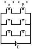
Six similar bulbs are connected as shown in the figure with a $DC$ source of $emf\; E$,and zero internal resistance. The ratio of power consumption by the bulbs when $(i)$ all are glowing and $(ii)$ in the situation when two from section $A$ and one from section $B$ are glowing,will be
A
$4:9$
B
$9:4$
C
$1:2$
D
$2:1$
Solution
(B) Let the resistance of each bulb be $R$.
Case $(i)$: All six bulbs are glowing. Section $A$ has $3$ bulbs in parallel,and section $B$ has $3$ bulbs in parallel. These two sections are in series. The equivalent resistance is $R_{eq_1} = (R/3) + (R/3) = 2R/3$. The power consumed is $P_1 = E^2 / R_{eq_1} = 3E^2 / 2R$.
Case $(ii)$: Two bulbs from section $A$ are in parallel (resistance $R/2$) and one bulb from section $B$ is in series with this combination. The equivalent resistance is $R_{eq_2} = R/2 + R = 3R/2$. The power consumed is $P_2 = E^2 / R_{eq_2} = 2E^2 / 3R$.
The ratio of power consumption is $P_1 : P_2 = (3E^2 / 2R) : (2E^2 / 3R) = 9 : 4$.
0 likes
View Solution193
Medium
Answer the following questions:
$(a)$ $A$ steady current flows in a metallic conductor of non-uniform cross-section. Which of these quantities is constant along the conductor: current, current density, electric field, drift speed?
$(b)$ Is Ohm's law universally applicable for all conducting elements? If not, give examples of elements which do not obey Ohm's law.
$(c)$ $A$ low voltage supply from which one needs high currents must have very low internal resistance. Why?
$(d)$ $A$ high tension $(HT)$ supply of, say, $6 \ kV$ must have a very large internal resistance. Why?
Solution
$(A)$ When a steady current flows in a metallic conductor of non-uniform cross-section, the current $(I)$ flowing through the conductor remains constant because charge cannot accumulate at any point. Since $I = J A = n e v_d A$, where $J$ is current density, $A$ is cross-sectional area, and $v_d$ is drift speed, $J$, $E$ (electric field), and $v_d$ are inversely proportional to $A$. Thus, they vary with the cross-section.
$(b)$ No, Ohm's law is not universally applicable. Elements that do not obey Ohm's law are called non-ohmic conductors. Examples include vacuum diodes, semiconductors, and junction diodes.
$(c)$ According to the relation $I = \frac{\varepsilon}{R + r}$, where $\varepsilon$ is the electromotive force and $r$ is the internal resistance, to obtain a high current $(I)$ from a low voltage source $(\varepsilon)$, the internal resistance $(r)$ must be very low.
$(d)$ $A$ high tension $(HT)$ supply must have a very large internal resistance to limit the current to a safe value. If the internal resistance were low, a short circuit would cause an extremely high current to flow, which could be dangerous and damage the equipment.
0 likes
View Solution194
Medium
$A$ room has an $AC$ running for $5$ hours a day at a voltage of $220$ $V$. The wiring of the room consists of $Cu$ wire of $1$ $mm$ radius and a length of $10$ $m$. Power consumption per day is $10$ commercial units. What fraction of it goes into Joule heating in the wires? What would happen if the wiring is made of aluminium of the same dimensions? $(\rho_{Cu} = 1.7 \times 10^{-8} \, \Omega m, \rho_{Al} = 2.7 \times 10^{-8} \, \Omega m)$
Solution
(A) Power consumption in $1$ day ($5$ hours) is $10$ units.
Power consumed in $1$ hour is $P = 10/5 = 2$ units = $2000$ $W$.
Since $P = VI$,the current $I = P/V = 2000/220 \approx 9.09$ $A$.
Resistance of the copper wire $R = \rho l / A = \rho l / (\pi r^2) = (1.7 \times 10^{-8} \times 10) / (3.14 \times (10^{-3})^2) = 1.7 \times 10^{-7} / 3.14 \times 10^{-6} \approx 0.054$ $\Omega$.
Power dissipated in the wire $P_{loss} = I^2 R = (9.09)^2 \times 0.054 \approx 4.46$ $W$.
Fraction of power lost = $P_{loss} / P_{total} = 4.46 / 2000 \approx 0.00223$ or $0.223\%$.
If aluminium is used,$\rho_{Al} = 2.7 \times 10^{-8} \, \Omega m$.
Since $R \propto \rho$,the resistance increases by a factor of $2.7/1.7 \approx 1.59$.
Thus,the power loss in the aluminium wire will be approximately $1.59$ times higher than in the copper wire.
0 likes
View Solution195
DifficultMCQ
First,a set of $n$ equal resistors of $10 \; \Omega$ each are connected in series to a battery of emf $20 \; V$ and internal resistance $10 \; \Omega$. $A$ current $I$ is observed to flow. Then,the $n$ resistors are connected in parallel to the same battery. It is observed that the current is increased $20$ times. The value of $n$ is .... .
A
$20$
B
$10$
C
$25$
D
$16$
Solution
(A) In the series connection,the equivalent resistance of the resistors is $R_{eq,s} = nR = 10n \; \Omega$.
The total resistance of the circuit is $R_{total,s} = 10 + 10n \; \Omega$.
The current in the series circuit is $I_s = \frac{20}{10 + 10n} = \frac{2}{1 + n} \; A$.
In the parallel connection,the equivalent resistance of the resistors is $R_{eq,p} = \frac{R}{n} = \frac{10}{n} \; \Omega$.
The total resistance of the circuit is $R_{total,p} = 10 + \frac{10}{n} = \frac{10n + 10}{n} \; \Omega$.
The current in the parallel circuit is $I_p = \frac{20}{\frac{10n + 10}{n}} = \frac{20n}{10(n + 1)} = \frac{2n}{n + 1} \; A$.
Given that the current increases $20$ times,we have $I_p = 20 I_s$.
Substituting the expressions: $\frac{2n}{n + 1} = 20 \times \frac{2}{n + 1}$.
Canceling the common terms,we get $2n = 40$,which implies $n = 20$.
0 likes
View Solution196
DifficultMCQ
The voltage drop across the $15\, \Omega$ resistance in the given figure is $.....V.$
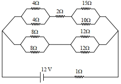
A
$8$
B
$60$
C
$6$
D
$9$
Solution
(C) First, simplify the circuit. The parallel combination of two $4\, \Omega$ resistors is $2\, \Omega$. The parallel combination of two $8\, \Omega$ resistors is $4\, \Omega$. The parallel combination of two $12\, \Omega$ resistors is $6\, \Omega$.
The upper branch has resistances in series: $2\, \Omega$ (from $4\, \Omega || 4\, \Omega$) + $2\, \Omega$ + $R_{p1}$ (where $R_{p1} = 15\, \Omega || 10\, \Omega = 6\, \Omega$). Total upper branch resistance $R_1 = 2 + 2 + 6 = 10\, \Omega$.
The lower branch has resistances in series: $4\, \Omega$ (from $8\, \Omega || 8\, \Omega$) + $6\, \Omega$ (from $12\, \Omega || 12\, \Omega$) = $10\, \Omega$.
The two branches are in parallel, so their equivalent resistance is $R_{eq_branches} = (10\, \Omega || 10\, \Omega) = 5\, \Omega$.
Total circuit resistance $R_{total} = 5\, \Omega + 1\, \Omega$ (internal) $= 6\, \Omega$.
Total current $I = V / R_{total} = 12\, V / 6\, \Omega = 2\, A$.
This current splits equally into the two $10\, \Omega$ branches, so $1\, A$ flows through the upper branch.
The voltage across the $15\, \Omega || 10\, \Omega$ parallel combination is $V_{AB} = I_{upper} \times R_{p1} = 1\, A \times 6\, \Omega = 6\, V$.
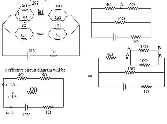
0 likes
View Solution197
DifficultMCQ
Due to cold weather,a $1\, m$ water pipe of cross-sectional area $1\, cm^2$ is filled with ice at $-10^{\circ}C$. Resistive heating is used to melt the ice. $A$ current of $0.5\, A$ is passed through a $4\, k\Omega$ resistance. Assuming that all the heat produced is used for melting,what is the minimum time required? (In $s$)
(Given: latent heat of fusion for water/ice $= 3.33 \times 10^5\, J/kg$,specific heat of ice $= 2 \times 10^3\, J/(kg\cdot K)$ and density of ice $= 10^3\, kg/m^3$)
(Given: latent heat of fusion for water/ice $= 3.33 \times 10^5\, J/kg$,specific heat of ice $= 2 \times 10^3\, J/(kg\cdot K)$ and density of ice $= 10^3\, kg/m^3$)
A
$0.353$
B
$35.3$
C
$3.53$
D
$70.6$
Solution
(B) Step $1$: Calculate the mass of the ice.
$m = \rho A \ell = 10^3\, kg/m^3 \times 10^{-4}\, m^2 \times 1\, m = 0.1\, kg$.
Step $2$: Calculate the total energy $Q$ required to raise the temperature of ice from $-10^{\circ}C$ to $0^{\circ}C$ and then melt it.
$Q = mc_{ice}\Delta T + mL_f$
$Q = 0.1 \times (2 \times 10^3 \times 10) + 0.1 \times (3.33 \times 10^5)$
$Q = 2 \times 10^3 + 3.33 \times 10^4 = 3.53 \times 10^4\, J$.
Step $3$: Calculate the time $t$ using the heat produced by the resistor.
$Q = I^2Rt$
$3.53 \times 10^4 = (0.5)^2 \times (4 \times 10^3) \times t$
$3.53 \times 10^4 = 0.25 \times 4000 \times t$
$3.53 \times 10^4 = 1000 \times t$
$t = 35.3\, s$.
0 likes
View Solution198
MediumMCQ
Column $- I$ gives certain physical terms associated with the flow of current through a metallic conductor. Column $- II$ gives some mathematical relations involving electrical quantities. Match Column $- I$ and Column $- II$ with appropriate relations.
| Column $- I$ | Column $- II$ |
| $(A)$ Drift Velocity | $(P)$ $\frac{m}{n e^{2} \rho}$ |
| $(B)$ Electrical Resistivity | $(Q)$ $n e v_{d}$ |
| $(C)$ Relaxation Period | $(R)$ $\frac{e E}{m} \tau$ |
| $(D)$ Current Density | $(S)$ $\frac{E}{J}$ |
A
$(A)-(R), (B)-(S), (C)-(P), (D)-(Q)$
B
$(A)-(R), (B)-(S), (C)-(Q), (D)-(P)$
C
$(A)-(R), (B)-(P), (C)-(S), (D)-(Q)$
D
$(A)-(R), (B)-(Q), (C)-(S), (D)-(P)$
Solution
(A) The drift velocity is given by $v_{d} = \frac{e E}{m} \tau$. Thus, $(A) \rightarrow (R)$.
The electrical resistivity $\rho$ is defined as the ratio of electric field to current density, $\rho = \frac{E}{J}$. Thus, $(B) \rightarrow (S)$.
The relaxation period $\tau$ is related to resistivity by $\rho = \frac{m}{n e^{2} \tau}$, which implies $\tau = \frac{m}{n e^{2} \rho}$. Thus, $(C) \rightarrow (P)$.
The current density $J$ is given by $J = n e v_{d}$. Thus, $(D) \rightarrow (Q)$.
Therefore, the correct matching is $(A)-(R), (B)-(S), (C)-(P), (D)-(Q)$.
0 likes
View Solution199
MediumMCQ
Given below are two statements:
Statement $I$: $A$ uniform wire of resistance $80\,\Omega$ is cut into four equal parts. These parts are now connected in parallel. The equivalent resistance of the combination will be $5\,\Omega$.
Statement $II$: Two resistances $2\,R$ and $3\,R$ are connected in parallel in an electric circuit. The value of thermal energy developed in $3\,R$ and $2\,R$ will be in the ratio $3:2$.
In the light of the above statements,choose the most appropriate answer from the options given below.
A
Both statement $I$ and statement $II$ are correct.
B
Both statement $I$ and statement $II$ are incorrect.
C
Statement $I$ is correct but statement $II$ is incorrect.
D
Statement $I$ is incorrect but statement $II$ is correct.
Solution
(C) Analysis of Statement $I$:
When a wire of resistance $R = 80\,\Omega$ is cut into $4$ equal parts,the resistance of each part becomes $r = R/4 = 80/4 = 20\,\Omega$.
When these $4$ resistors are connected in parallel,the equivalent resistance $R_{eq}$ is given by:
$1/R_{eq} = 1/r + 1/r + 1/r + 1/r = 4/r = 4/20 = 1/5$.
Thus,$R_{eq} = 5\,\Omega$. Statement $I$ is correct.
Analysis of Statement $II$:
When resistors are connected in parallel,the potential difference $V$ across each is the same.
The thermal energy (heat) developed in time $t$ is given by $H = (V^2/R)t$.
Therefore,$H \propto 1/R$.
The ratio of thermal energy developed in $3\,R$ and $2\,R$ is:
$H_{3R} / H_{2R} = (V^2 / 3R) / (V^2 / 2R) = 2R / 3R = 2/3$.
The ratio is $2:3$,not $3:2$. Statement $II$ is incorrect.
Conclusion: Statement $I$ is correct but statement $II$ is incorrect.
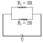
0 likes
View Solution200
DifficultMCQ
Two rods of copper $(Cu)$ and iron $(Fe)$ with the same cross-sectional area are joined at $S$ and a steady current $I$ flows through the rods as shown in the figure. Choose the most appropriate representation of charges accumulated near the junction $S$.
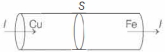
A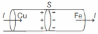
B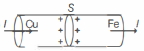
C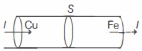
D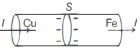
Solution
(A) When a steady current $I$ flows through a junction between two different metals,charge accumulation occurs at the interface due to the difference in their conductivities.
The current density $J$ is given by $J = \sigma E$,where $\sigma$ is the conductivity and $E$ is the electric field. Since the current $I$ and the cross-sectional area $A$ are the same for both rods,the current density $J = I/A$ is constant.
At the junction,the continuity of current requires that the normal component of the current density be continuous. However,the electric field $E = J/\sigma$ must change because the conductivity $\sigma$ of copper is higher than that of iron $(\sigma_{Cu} > \sigma_{Fe})$.
According to Gauss's law,the surface charge density $\rho_s$ at the interface is given by $\rho_s = \epsilon_0 (E_{Fe} - E_{Cu})$. Since $\sigma_{Cu} > \sigma_{Fe}$,it follows that $E_{Fe} > E_{Cu}$. Thus,$\rho_s$ is positive,meaning positive charge accumulates on the copper side and negative charge accumulates on the iron side of the junction to maintain the steady current flow.
Therefore,the correct representation is shown in option $(A)$ and $(B)$ (as they are identical in the provided images). Based on the standard interpretation,the positive charge accumulates on the side of higher conductivity $(Cu)$ and negative charge on the side of lower conductivity $(Fe)$.
0 likes
View SolutionCurrent Electricity — Mix Examples-Current Electricity · Frequently Asked Questions
1Are these Current Electricity questions useful for JEE and NEET?
Yes. All questions in this section are mapped to JEE Main and NEET exam patterns. Previous year questions from JEE Main, NEET, GUJCET and state-level exams are included with full solutions.
2Can I switch to Hindi or Gujarati for these questions?
Yes. Use the language tabs in the hero section or the sidebar to view the same questions and solutions in English, Hindi or Gujarati.
3How do I generate a question paper from this subtopic?
Use the Vedclass Exam Paper Generator — select the chapter and subtopic, set difficulty, and generate Sets A, B, C, D automatically. First 3 chapters of every subject are free.
Vedclass Products
For Students
Vedclass Test Series
Mock tests in real JEE/NEET style with performance analysis. 5-day free trial.
Start Free TrialFor Teachers
Exam Paper Generator
Generate Set A/B/C/D papers from this chapter in 2 minutes. 3 chapters free.
Try FreeFor Institutes
Online Exam Module
Live online exams with unlimited students, 360° analytics & white-label branding.
See DemoFor Teachers & Institutes
Generate a Current Electricity Exam Paper in 2 Minutes
Select subtopic & difficulty — Sets A, B, C, D auto-generated with No Repeat logic.
First 3 chapters of every subject are free — no payment required.