
A English
RL, RC and LC AC Circuits Questions in English
Class 12 Physics · Alternating Current · RL, RC and LC AC Circuits
281+
Questions
English
Language
100%
With Solutions
Showing 49 of 281 questions in English
101
EasyMCQ
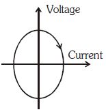
The graph shows current $v/s$ voltage in a series $RLC$ $A.C.$ circuit. The arrow indicates the direction that this curve is drawn as time progresses. In this plot,the
A
Current lags the voltage by about $90^o$
B
Current leads the voltage by about $90^o$
C
Current and voltage are in phase
D
Current and voltage are $180^o$ out of phase
Solution
(B) In an $A.C.$ circuit,the relationship between current $(I)$ and voltage $(V)$ can be represented by a Lissajous figure in a $I-V$ plot.
For a purely capacitive circuit,current leads voltage by $90^o$.
For a purely inductive circuit,current lags voltage by $90^o$.
In the given graph,the $x$-axis represents current and the $y$-axis represents voltage.
As time progresses (indicated by the arrow),the curve traces an ellipse.
At the point where the current is maximum (on the $x$-axis),the voltage is zero and increasing.
This indicates that the current reaches its peak before the voltage reaches its peak.
Therefore,the current leads the voltage by approximately $90^o$.
0 likes
View Solution102
DifficultMCQ
An induction coil has an impedance of $10\,\Omega$. When an $AC$ signal of frequency $1000\,Hz$ is applied to the coil,the voltage leads the current by $45^o$. The inductance of the coil is
A
$\frac{1}{20\pi}\,H$
B
$\frac{1}{\sqrt{2} \times 200\pi}\,H$
C
$\frac{1}{\sqrt{2} \times 20\pi}\,H$
D
$\frac{1}{200\pi}\,H$
Solution
(B) Given: Impedance $Z = 10\,\Omega$,frequency $f = 1000\,Hz$,phase angle $\phi = 45^\circ$.
The phase angle in an $RL$ circuit is given by $\tan \phi = \frac{\omega L}{R}$.
Since $\phi = 45^\circ$,$\tan 45^\circ = 1$,so $\omega L = R$.
The impedance is $Z = \sqrt{R^2 + (\omega L)^2} = 10\,\Omega$.
Substituting $R = \omega L$,we get $Z = \sqrt{(\omega L)^2 + (\omega L)^2} = \sqrt{2}(\omega L) = 10$.
Thus,$\omega L = \frac{10}{\sqrt{2}} = 5\sqrt{2}\,\Omega$.
We know $\omega = 2\pi f = 2\pi \times 1000 = 2000\pi\,rad/s$.
Therefore,$L = \frac{5\sqrt{2}}{\omega} = \frac{5\sqrt{2}}{2000\pi} = \frac{\sqrt{2}}{400\pi} = \frac{1}{200\sqrt{2}\pi}\,H$.
Wait,re-evaluating the calculation: $L = \frac{5\sqrt{2}}{2000\pi} = \frac{1}{400\pi/\sqrt{2}} = \frac{1}{200\sqrt{2}\pi}$.
Checking the options provided,the correct expression is $L = \frac{1}{\sqrt{2} \times 200\pi}$.
0 likes
View Solution103
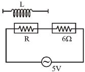
MediumMCQ
Two resistors are connected in series across a $5\,V\,rms$ source of alternating potential. The potential difference across the $6\,\Omega$ resistor is $3\,V$. If $R$ is replaced by a pure inductor $L$ of such magnitude that the current remains the same,then the potential difference across $L$ is.......$V$.
A
$1$
B
$2$
C
$3$
D
$4$
Solution
(D) In the initial circuit,the resistors $R$ and $6\,\Omega$ are in series. The potential difference across the $6\,\Omega$ resistor is $V_{6\Omega} = 3\,V$.
Using Ohm's law,the current in the circuit is $I = \frac{V_{6\Omega}}{6\,\Omega} = \frac{3}{6} = 0.5\,A$.
The total voltage is $V = 5\,V$. In a series circuit with $R$ and $6\,\Omega$,$V = I \sqrt{(R+6)^2} = I(R+6)$. Thus,$5 = 0.5(R+6)$,which gives $R+6 = 10$,so $R = 4\,\Omega$.
When $R$ is replaced by an inductor $L$ with reactance $X_L$,the circuit becomes an $L-R$ series circuit. The current remains $I = 0.5\,A$.
The impedance of the new circuit is $Z = \sqrt{X_L^2 + 6^2}$.
Using $V = IZ$,we have $5 = 0.5 \sqrt{X_L^2 + 36}$.
$10 = \sqrt{X_L^2 + 36} \implies 100 = X_L^2 + 36 \implies X_L^2 = 64 \implies X_L = 8\,\Omega$.
The potential difference across the inductor is $V_L = I \cdot X_L = 0.5 \times 8 = 4\,V$.
0 likes
View Solution104
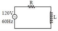
MediumMCQ
$A$ resistor and a pure inductor are connected to an $AC$ supply of $120\,V$ and $50\,Hz$. The current in the circuit is $3\,A$. If the power consumed in the circuit is $108\,W$,then the resistance in the circuit is.....$\Omega $
A
$12$
B
$40$
C
$\sqrt{52 \times 28}$
D
$360$
Solution
(A) The power consumed in an $AC$ circuit is given by the formula:
$P = V_{rms} I_{rms} \cos\phi$
Since $\cos\phi = \frac{R}{Z}$,we have:
$P = V_{rms} I_{rms} \left( \frac{R}{Z} \right)$ ..........$(1)$
First,calculate the total impedance $Z$ of the circuit:
$Z = \frac{V_{rms}}{I_{rms}} = \frac{120}{3} = 40\,\Omega$
Now,substitute the values into equation $(1)$:
$108 = (120)(3) \times \frac{R}{40}$
$108 = 360 \times \frac{R}{40}$
$108 = 9R$
$R = \frac{108}{9} = 12\,\Omega$
Therefore,the resistance in the circuit is $12\,\Omega$.
0 likes
View Solution105
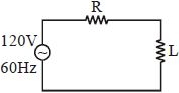
MediumMCQ
In the given circuit,the potential difference across the resistance is $54 \, V$ and the power consumed by it is $16 \, W$. If the $AC$ frequency is $60 \, Hz$,find the value of $L$ in $H$.
A
$1$
B
$2$
C
$5$
D
$4$
Solution
(A) The total voltage $V$ is given by $V^2 = V_R^2 + V_L^2$,where $V_R = 54 \, V$ and $V = 120 \, V$.
$V_L = \sqrt{V^2 - V_R^2} = \sqrt{120^2 - 54^2} = \sqrt{14400 - 2916} = \sqrt{11484} \approx 107.16 \, V$.
The power consumed by the resistor is $P = V_R \cdot I$,so $I = P / V_R = 16 / 54 \, A$.
The voltage across the inductor is $V_L = I \cdot X_L = I \cdot (2 \pi f L)$.
Substituting the values: $107.16 = (16 / 54) \cdot 2 \cdot \pi \cdot 60 \cdot L$.
$107.16 = (16 / 54) \cdot 377 \cdot L$.
$L = (107.16 \cdot 54) / (16 \cdot 377) \approx 5786.64 / 6032 \approx 0.96 \, H$.
Rounding to the nearest integer,$L \approx 1 \, H$.
0 likes
View Solution106
MediumMCQ
If a dielectric slab is inserted in the capacitor of the given $RC$ circuit,then the brightness of the bulb will:
A
Increase
B
Decrease
C
Remain the same
D
First increase then decrease
Solution
(A) $1$. The brightness of the bulb depends on the power dissipated in the circuit,which is given by $P = I_{rms}^2 R_{bulb}$.
$2$. The current in the $RC$ circuit is given by $I_{rms} = \frac{V_{rms}}{Z}$,where $Z = \sqrt{R_{total}^2 + X_C^2}$ is the impedance of the circuit.
$3$. Here,$X_C = \frac{1}{\omega C}$ is the capacitive reactance.
$4$. When a dielectric slab is inserted into the capacitor,the capacitance $C$ increases ($C' = KC$,where $K > 1$).
$5$. As $C$ increases,the capacitive reactance $X_C = \frac{1}{\omega C}$ decreases.
$6$. Since $Z = \sqrt{R_{total}^2 + X_C^2}$,a decrease in $X_C$ leads to a decrease in the total impedance $Z$.
$7$. $A$ decrease in impedance $Z$ results in an increase in the current $I_{rms}$ flowing through the circuit.
$8$. Since $P = I_{rms}^2 R_{bulb}$,an increase in $I_{rms}$ leads to an increase in the power dissipated by the bulb,hence the brightness of the bulb will increase.
0 likes
View Solution107
MediumMCQ
The impedance of a circuit,when a resistance $R$ and an inductor of inductance $L$ are connected in series in an $AC$ circuit of frequency $f$ is
A
$\sqrt {R^2 + 2{\pi ^2}{f^2}{L^2}} $
B
$\sqrt {R^2 + 4{\pi ^2}{f^2}{L^2}} $
C
$\sqrt {R + 4{\pi ^2}{f^2}{L^2}} $
D
$\sqrt {R + 2{\pi ^2}{f^2}{L^2}} $
Solution
(B) In an $L-R$ series circuit,the impedance $Z$ is given by the formula:
$Z = \sqrt{R^2 + X_L^2}$
where $R$ is the resistance and $X_L$ is the inductive reactance.
The inductive reactance $X_L$ is defined as:
$X_L = \omega L = 2 \pi f L$
Substituting the value of $X_L$ into the impedance formula:
$Z = \sqrt{R^2 + (2 \pi f L)^2}$
$Z = \sqrt{R^2 + 4 \pi^2 f^2 L^2}$
$Z = \sqrt{R^2 + X_L^2}$
where $R$ is the resistance and $X_L$ is the inductive reactance.
The inductive reactance $X_L$ is defined as:
$X_L = \omega L = 2 \pi f L$
Substituting the value of $X_L$ into the impedance formula:
$Z = \sqrt{R^2 + (2 \pi f L)^2}$
$Z = \sqrt{R^2 + 4 \pi^2 f^2 L^2}$
0 likes
View Solution108
MediumMCQ
If $E = 200\,V$,$R = 25\,\Omega$,$L = 2\,H$,and $C = 2\,\mu F$ and the frequency is variable,then the current at $f = 0$ and $f = \infty$ will be respectively:
A
$0\,A, 8\,A$
B
$8\,A, 0\,A$
C
$8\,A, 8\,A$
D
$0\,A, 0\,A$
Solution
(D) In a series $LCR$ circuit,the impedance $Z$ is given by $Z = \sqrt{R^2 + (X_L - X_C)^2}$,where $X_L = 2\pi fL$ and $X_C = \frac{1}{2\pi fC}$.
At $f = 0$ ($DC$ condition),the capacitive reactance $X_C = \frac{1}{2\pi fC} = \infty$. Since $X_C$ is in series,the total impedance $Z = \infty$. Therefore,the current $I = \frac{E}{Z} = \frac{200}{\infty} = 0\,A$.
At $f = \infty$,the inductive reactance $X_L = 2\pi fL = \infty$. Since $X_L$ is in series,the total impedance $Z = \infty$. Therefore,the current $I = \frac{E}{Z} = \frac{200}{\infty} = 0\,A$.
Thus,the current at both $f = 0$ and $f = \infty$ is $0\,A$.
0 likes
View Solution109
EasyMCQ
When an $AC$ generator of $120 \, V$ is connected in series with a capacitor and a resistor of $30 \, \Omega$,the circuit carries a current of $1.5 \, A$. The potential difference across the capacitor will be ..... $V$.
A
$1.11$
B
$111$
C
$0$
D
$220$
Solution
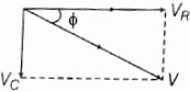
(B) The total voltage $V$ in an $RC$ series circuit is given by $V^2 = V_R^2 + V_C^2$.
First,calculate the potential difference across the resistor: $V_R = I \times R = 1.5 \, A \times 30 \, \Omega = 45 \, V$.
Now,substitute the values into the formula: $V_C = \sqrt{V^2 - V_R^2}$.
$V_C = \sqrt{(120)^2 - (45)^2}$.
$V_C = \sqrt{14400 - 2025} = \sqrt{12375}$.
$V_C \approx 111.24 \, V$.
Rounding to the nearest whole number,the potential difference across the capacitor is $111 \, V$.
0 likes
View Solution110
MediumMCQ
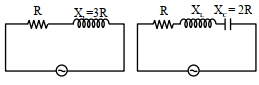
In a series $A.C.$ circuit,the current and voltage are given respectively as:
$I = 10 \sin \omega t$; $V = 10 \sin \left( \omega t + \pi / 4 \right)$
Then,which of the following elements may be present in the circuit?
$(a)$ Only $C$
$(b)$ All $L, C$ and $R$
$(c)$ Both $C$ and $R$
$(d)$ Both $L$ and $R$
$I = 10 \sin \omega t$; $V = 10 \sin \left( \omega t + \pi / 4 \right)$
Then,which of the following elements may be present in the circuit?
$(a)$ Only $C$
$(b)$ All $L, C$ and $R$
$(c)$ Both $C$ and $R$
$(d)$ Both $L$ and $R$
A
$(a), (c)$
B
$(a), (b), (c)$
C
$(b), (d)$
D
$(b), (c)$
Solution
(C) Given:
$I = 10 \sin \omega t$
$V = 10 \sin \left( \omega t + \pi / 4 \right)$
Comparing these with the general forms $I = I_0 \sin \omega t$ and $V = V_0 \sin (\omega t + \phi)$,we see that the phase difference is $\phi = \pi / 4$.
Since the voltage leads the current by a phase angle of $\pi / 4$ (positive phase angle),the circuit must be inductive in nature.
An $RL$ circuit (Resistor and Inductor) results in a voltage that leads the current.
An $LCR$ circuit can also result in a voltage that leads the current if the inductive reactance $X_L$ is greater than the capacitive reactance $X_C$ (i.e.,$X_L > X_C$).
Therefore,the circuit could contain both $L$ and $R$,or it could contain all three elements $L, C,$ and $R$ provided the net reactance is inductive.
Thus,options $(b)$ and $(d)$ are correct.
0 likes
View Solution111
DifficultMCQ
In a given series $LCR$ circuit,$R = 4\,\Omega$,$X_L = 5\,\Omega$,and $X_C = 8\,\Omega$. The current:
A
Leads the voltage by $\tan^{-1}(3/4)$
B
Leads the voltage by $\tan^{-1}(5/8)$
C
Lags the voltage by $\tan^{-1}(3/4)$
D
Lags the voltage by $\tan^{-1}(5/8)$
Solution
(A) The phase angle $\phi$ in an $LCR$ series circuit is given by $\tan \phi = \frac{X_C - X_L}{R}$.
Substituting the given values: $\tan \phi = \frac{8 - 5}{4} = \frac{3}{4}$.
Therefore,$\phi = \tan^{-1}(3/4)$.
Since $X_C > X_L$,the circuit is capacitive in nature,which means the current leads the voltage by a phase angle of $\tan^{-1}(3/4)$.
Substituting the given values: $\tan \phi = \frac{8 - 5}{4} = \frac{3}{4}$.
Therefore,$\phi = \tan^{-1}(3/4)$.
Since $X_C > X_L$,the circuit is capacitive in nature,which means the current leads the voltage by a phase angle of $\tan^{-1}(3/4)$.
0 likes
View Solution112
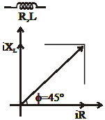
MediumMCQ
The time constant of the given $LR$ circuit is $\tau$. If the battery is replaced by an $AC$ source having voltage $V = V_0 \cos \omega t$,the power factor of the circuit will be

A
$\omega \tau$
B
$\frac{1}{\sqrt{1 + (\omega \tau)^2}}$
C
$\sqrt{1 + (\omega \tau)^2}$
D
None
Solution
(B) For an $LR$ series circuit,the time constant is given by $\tau = \frac{L}{R}$.
When the battery is replaced by an $AC$ source,the impedance $Z$ of the $LR$ circuit is $Z = \sqrt{R^2 + X_L^2} = \sqrt{R^2 + (\omega L)^2}$.
The power factor $\cos \phi$ is defined as $\cos \phi = \frac{R}{Z}$.
Substituting the expression for $Z$,we get $\cos \phi = \frac{R}{\sqrt{R^2 + \omega^2 L^2}}$.
Dividing the numerator and denominator by $R$,we get $\cos \phi = \frac{1}{\sqrt{1 + \omega^2 (\frac{L}{R})^2}}$.
Since $\tau = \frac{L}{R}$,substituting this into the equation gives $\cos \phi = \frac{1}{\sqrt{1 + \omega^2 \tau^2}}$.
0 likes
View Solution113
MediumMCQ
In a circuit made up of a resistance $4\,\Omega$ and an inductance $0.01\,H$,an alternating $emf$ of $200\,V$ at $50\,Hz$ is connected. The phase difference between the current and the $emf$ in the circuit is:
A
$\tan^{-1}\left(\frac{\pi}{4}\right)$
B
$\tan^{-1}\left(\frac{\pi}{3}\right)$
C
$\tan^{-1}\left(\frac{\pi}{2}\right)$
D
$\tan^{-1}(\pi)$
Solution
(A) The phase difference $\phi$ in an $RL$ circuit is given by the formula $\tan \phi = \frac{X_L}{R}$.
Here,$X_L = \omega L = 2\pi f L$.
Given: $R = 4\,\Omega$,$L = 0.01\,H$,$f = 50\,Hz$.
Substituting the values: $\tan \phi = \frac{2\pi \times 50 \times 0.01}{4}$.
$\tan \phi = \frac{100\pi \times 0.01}{4} = \frac{\pi}{4}$.
Therefore,the phase difference is $\phi = \tan^{-1}\left(\frac{\pi}{4}\right)$.
0 likes
View Solution114
MediumMCQ
In an $AC$ circuit,the potential differences across an inductance and a resistance joined in series are $16 \, V$ and $20 \, V$ respectively. The total potential difference of the source is .......... $V$.
A
$20$
B
$25.6$
C
$31.9$
D
$53.5$
Solution
(B) In an $AC$ series $LR$ circuit,the voltage across the resistor $(V_R)$ and the inductor $(V_L)$ are out of phase by $90^{\circ}$.
The total potential difference $(V)$ of the source is given by the phasor sum:
$V = \sqrt{V_R^2 + V_L^2}$
Given:
$V_L = 16 \, V$
$V_R = 20 \, V$
Substituting the values:
$V = \sqrt{(20)^2 + (16)^2}$
$V = \sqrt{400 + 256}$
$V = \sqrt{656}$
$V \approx 25.61 \, V$
Rounding to the nearest provided option,the total potential difference is $25.6 \, V$.
0 likes
View Solution115
DifficultMCQ
$A$ coil has an inductance of $0.7 \, H$ and is joined in series with a resistance of $220 \, \Omega$. When an alternating $emf$ of $220 \, V$ at $50 \, Hz$ is applied to it,the phase angle by which the current lags behind the applied $emf$ and the wattless component of the current in the circuit are respectively:
A
$30^o, \, 1 \, A$
B
$45^o, \, 0.5 \, A$
C
$60^o, \, 1.5 \, A$
D
none of these
Solution
(B) Given: $L = 0.7 \, H$,$R = 220 \, \Omega$,$V_{rms} = 220 \, V$,$f = 50 \, Hz$.
First,calculate the inductive reactance $X_L$:
$X_L = 2 \pi f L = 2 \times \frac{22}{7} \times 50 \times 0.7 = 220 \, \Omega$.
Phase angle $\phi$ is given by:
$\tan \phi = \frac{X_L}{R} = \frac{220}{220} = 1 \implies \phi = 45^o$.
The total impedance $Z$ is:
$Z = \sqrt{R^2 + X_L^2} = \sqrt{220^2 + 220^2} = 220\sqrt{2} \, \Omega$.
The $rms$ current $I_{rms}$ is:
$I_{rms} = \frac{V_{rms}}{Z} = \frac{220}{220\sqrt{2}} = \frac{1}{\sqrt{2}} \, A$.
The wattless component of current is $I_{rms} \sin \phi$:
$I_{wattless} = I_{rms} \sin 45^o = \frac{1}{\sqrt{2}} \times \frac{1}{\sqrt{2}} = 0.5 \, A$.
Thus,the phase angle is $45^o$ and the wattless component is $0.5 \, A$.
0 likes
View Solution116
EasyMCQ
An inductor and a resistor in series are connected to an $A.C.$ supply of variable frequency. As the frequency of the source is increased,the phase angle between current and the potential difference across $L$ will
A
first increase and then decrease
B
first decrease and then increase
C
go on decreasing
D
go on increasing
Solution
(D) In a pure inductor,the current lags behind the potential difference across the inductor by a phase angle of $\pi/2$ radians (or $90^{\circ}$).
This phase relationship is independent of the frequency of the $A.C.$ source.
Therefore,the phase angle between the current and the potential difference across the inductor $L$ remains constant at $90^{\circ}$ regardless of the change in frequency.
However,if the question refers to the phase angle $\phi$ of the entire $LR$ series circuit,it is given by $\tan \phi = \frac{X_L}{R} = \frac{\omega L}{R} = \frac{2\pi f L}{R}$.
As the frequency $f$ increases,$\tan \phi$ increases,and thus the phase angle $\phi$ between the source voltage and current increases.
Given the specific phrasing 'phase angle between current and the potential difference across $L$',the answer is that it remains constant. Since this is not an option,the question likely intends to ask for the phase angle of the circuit,which increases as frequency increases.
0 likes
View Solution117
MediumMCQ
$A$ coil has a resistance of $30\,\Omega$ and an inductive reactance of $20\,\Omega$ at a frequency of $50\,Hz$. If an $AC$ source of $200\,V$ and $100\,Hz$ is connected across the coil,the current in the coil will be.......$A$
A
$4$
B
$8$
C
$\frac{20}{\sqrt{13}}$
D
$2$
Solution
(A) Given,resistance $R = 30\,\Omega$ and inductive reactance $X_L = 20\,\Omega$ at frequency $f = 50\,Hz$.
Since $X_L = 2\pi f L$,we have $20 = 2\pi(50)L$,which implies $L = \frac{20}{100\pi} = \frac{1}{5\pi}\,H$.
When the frequency is changed to $f' = 100\,Hz$,the new inductive reactance $X_L'$ is $X_L' = 2\pi f' L = 2\pi(100)(\frac{1}{5\pi}) = 40\,\Omega$.
The impedance $Z$ of the coil at $100\,Hz$ is $Z = \sqrt{R^2 + (X_L')^2} = \sqrt{30^2 + 40^2} = \sqrt{900 + 1600} = \sqrt{2500} = 50\,\Omega$.
The current $I$ in the coil is given by $I = \frac{V}{Z} = \frac{200}{50} = 4\,A$.
0 likes
View Solution118
MediumMCQ
$A$ circuit when connected to an $A.C.$ source of $12 \; V$ gives a current of $0.2 \; A$. The same circuit when connected to a $D.C.$ source of $12 \; V$,gives a current of $0.4 \; A$. The circuit is
A
series $LR$
B
series $RC$
C
series $LC$
D
series $LCR$
Solution
(A) For the $A.C.$ source,the impedance $Z = \frac{V}{I_{AC}} = \frac{12 \; V}{0.2 \; A} = 60 \; \Omega$.
For the $D.C.$ source,the resistance $R = \frac{V}{I_{DC}} = \frac{12 \; V}{0.4 \; A} = 30 \; \Omega$.
Since $Z > R$,the circuit must contain an inductor $(L)$ in addition to the resistor $(R)$.
In a $D.C.$ circuit,an ideal capacitor acts as an open circuit (infinite resistance),but since current flows in the $D.C.$ case,the circuit cannot contain a capacitor in series. Therefore,the circuit is a series $LR$ circuit.
0 likes
View Solution119
DifficultMCQ
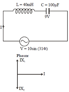
In an $LC$ circuit,the inductance $L = 40 \; mH$ and capacitance $C = 100 \; \mu F$. If a voltage $V(t) = 10 \sin (314 t)$ is applied to the circuit,the current in the circuit is given by:
A
$0.52 \cos 314 t$
B
$0.52 \sin 314 t$
C
$10 \cos 314 t$
D
$5.2 \cos 314 t$
Solution
(A) Given: $L = 40 \times 10^{-3} \; H$,$C = 100 \times 10^{-6} \; F$,$V(t) = 10 \sin (314 t)$.
Here,$\omega = 314 \; rad/s$.
Inductive reactance $X_{L} = \omega L = 314 \times 40 \times 10^{-3} = 12.56 \; \Omega$.
Capacitive reactance $X_{C} = \frac{1}{\omega C} = \frac{1}{314 \times 100 \times 10^{-6}} = \frac{10^{4}}{314} \approx 31.85 \; \Omega$.
Since $X_{C} > X_{L}$,the circuit is capacitive.
The net reactance $X = X_{C} - X_{L} = 31.85 - 12.56 = 19.29 \; \Omega$.
The peak current $I_{m} = \frac{V_{m}}{X} = \frac{10}{19.29} \approx 0.52 \; A$.
In a capacitive circuit,the current leads the voltage by $\frac{\pi}{2}$.
Thus,$I(t) = I_{m} \sin (\omega t + \frac{\pi}{2}) = 0.52 \sin (314 t + \frac{\pi}{2}) = 0.52 \cos (314 t)$.
0 likes
View Solution120
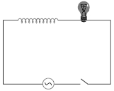
Medium
$A$ light bulb and an open coil inductor are connected to an $AC$ source through a key as shown in the figure. The switch is closed and after some time,an iron rod is inserted into the interior of the inductor. Does the glow of the light bulb $(a)$ increase,$(b)$ decrease,or $(c)$ remain unchanged? Give your answer with reasons.
Solution
(B) When the iron rod is inserted into the inductor,the magnetic permeability of the core increases,which in turn increases the self-inductance $(L)$ of the coil.
The inductive reactance of the coil is given by $X_L = \omega L$. As $L$ increases,the inductive reactance $X_L$ also increases.
The total impedance of the series circuit is $Z = \sqrt{R^2 + X_L^2}$,where $R$ is the resistance of the bulb. As $X_L$ increases,the total impedance $Z$ of the circuit increases.
Since the source voltage $V$ is constant,the current in the circuit $I = V/Z$ decreases.
The glow of the light bulb depends on the power dissipated,$P = I^2 R$. Since the current $I$ decreases,the power dissipated in the bulb decreases,and therefore,the glow of the light bulb decreases.
0 likes
View Solution121
Medium
$A$ resistor of $200 \; \Omega$ and a capacitor of $15.0 \; \mu F$ are connected in series to a $220 \; V, 50 \; Hz$ $ac$ source.
$(a)$ Calculate the current in the circuit.
$(b)$ Calculate the voltage $(rms)$ across the resistor and the capacitor. Is the algebraic sum of these voltages more than the source voltage? If yes,resolve the paradox.
$(a)$ Calculate the current in the circuit.
$(b)$ Calculate the voltage $(rms)$ across the resistor and the capacitor. Is the algebraic sum of these voltages more than the source voltage? If yes,resolve the paradox.
Solution
(A) $R = 200 \; \Omega, C = 15.0 \; \mu F = 15.0 \times 10^{-6} \; F$
$V = 220 \; V, \nu = 50 \; Hz$
$(a)$ To calculate the current,we need the impedance $Z$ of the circuit:
$X_C = \frac{1}{2 \pi \nu C} = \frac{1}{2 \times 3.14 \times 50 \times 15.0 \times 10^{-6}} \approx 212.3 \; \Omega$
$Z = \sqrt{R^2 + X_C^2} = \sqrt{200^2 + 212.3^2} \approx 291.67 \; \Omega$
$I = \frac{V}{Z} = \frac{220}{291.67} \approx 0.754 \; A$
$(b)$ The voltage across the resistor is $V_R = I R = 0.754 \times 200 = 150.8 \; V$.
The voltage across the capacitor is $V_C = I X_C = 0.754 \times 212.3 = 160.1 \; V$.
The algebraic sum is $150.8 + 160.1 = 310.9 \; V$,which is greater than the source voltage of $220 \; V$. This is not a paradox because $V_R$ and $V_C$ are not in phase. $V_R$ is in phase with the current,while $V_C$ lags the current by $90^{\circ}$. The total voltage is the phasor sum: $V = \sqrt{V_R^2 + V_C^2} = \sqrt{150.8^2 + 160.1^2} \approx 220 \; V$.
0 likes
View Solution122
MediumMCQ
$A$ radio can tune over the frequency range of a portion of $MW$ broadcast band: ($800 \;kHz$ to $1200 \;kHz$). If its $LC$ circuit has an effective inductance of $200 \;\mu H$,what must be the range of its variable capacitor?
A
$88 \;pF$ to $198 \;pF$
B
$198 \;pF$ to $88 \;pF$
C
$100 \;pF$ to $200 \;pF$
D
$50 \;pF$ to $150 \;pF$
Solution
(A) The resonant frequency of an $LC$ circuit is given by $f = \frac{1}{2\pi \sqrt{LC}}$.
Rearranging for capacitance,we get $C = \frac{1}{4\pi^2 f^2 L}$.
Given $L = 200 \;\mu H = 200 \times 10^{-6} \;H$.
For $f_1 = 800 \;kHz = 800 \times 10^3 \;Hz$:
$C_1 = \frac{1}{4 \times (3.14)^2 \times (800 \times 10^3)^2 \times 200 \times 10^{-6}} \approx 198 \;pF$.
For $f_2 = 1200 \;kHz = 1200 \times 10^3 \;Hz$:
$C_2 = \frac{1}{4 \times (3.14)^2 \times (1200 \times 10^3)^2 \times 200 \times 10^{-6}} \approx 88 \;pF$.
Thus,the range of the variable capacitor is $88 \;pF$ to $198 \;pF$.
0 likes
View Solution123
Medium
$A$ coil of inductance $0.50 \; H$ and resistance $100 \; \Omega$ is connected to a $240 \; V, 50 \; Hz$ $AC$ supply.
$(a)$ What is the maximum current in the coil?
$(b)$ What is the time lag between the voltage maximum and the current maximum?
$(a)$ What is the maximum current in the coil?
$(b)$ What is the time lag between the voltage maximum and the current maximum?
Solution
(A) Given:
Inductance $L = 0.50 \; H$
Resistance $R = 100 \; \Omega$
$RMS$ Voltage $V_{rms} = 240 \; V$
Frequency $f = 50 \; Hz$
$(a)$ Peak voltage $V_0 = \sqrt{2} \times V_{rms} = 1.414 \times 240 = 339.41 \; V$.
Angular frequency $\omega = 2 \pi f = 2 \pi \times 50 = 100 \pi \; rad/s$.
Impedance $Z = \sqrt{R^2 + (\omega L)^2} = \sqrt{100^2 + (100 \pi \times 0.5)^2} = \sqrt{10000 + 24674} = \sqrt{34674} \approx 186.21 \; \Omega$.
Maximum current $I_0 = \frac{V_0}{Z} = \frac{339.41}{186.21} \approx 1.82 \; A$.
$(b)$ The phase angle $\phi$ is given by $\tan \phi = \frac{\omega L}{R} = \frac{100 \pi \times 0.5}{100} = \frac{\pi}{2} \approx 1.57$.
$\phi = \tan^{-1}(1.57) \approx 57.5^{\circ}$.
Converting to radians: $\phi = 57.5 \times \frac{\pi}{180} \approx 1.003 \; rad$.
The time lag $\Delta t = \frac{\phi}{\omega} = \frac{1.003}{100 \pi} \approx 3.19 \times 10^{-3} \; s = 3.2 \; ms$.
0 likes
View Solution124
Medium
$A$ coil of inductance $0.50 \; H$ and resistance $100 \; \Omega$ is connected to a high-frequency supply $(240 \; V, 10 \; kHz)$.
$(a)$ What is the maximum current in the coil?
$(b)$ What is the time lag between the voltage maximum and the current maximum?
Hence,explain the statement that at very high frequency,an inductor in a circuit nearly amounts to an open circuit. How does an inductor behave in a $DC$ circuit after the steady state?
Solution
(A) Given: Inductance $L = 0.50 \; H$,Resistance $R = 100 \; \Omega$,$RMS$ Voltage $V_{rms} = 240 \; V$,Frequency $\nu = 10 \; kHz = 10^4 \; Hz$.
$(a)$ Peak voltage $V_0 = V_{rms} \sqrt{2} = 240 \sqrt{2} \approx 339.4 \; V$.
Angular frequency $\omega = 2 \pi \nu = 2 \pi \times 10^4 \; rad/s$.
Inductive reactance $X_L = \omega L = 2 \pi \times 10^4 \times 0.5 = \pi \times 10^4 \approx 31416 \; \Omega$.
Impedance $Z = \sqrt{R^2 + X_L^2} = \sqrt{100^2 + (31416)^2} \approx 31416 \; \Omega$.
Maximum current $I_0 = \frac{V_0}{Z} = \frac{339.4}{31416} \approx 1.08 \times 10^{-2} \; A$.
$(b)$ Phase angle $\phi = \tan^{-1}(\frac{\omega L}{R}) = \tan^{-1}(\frac{31416}{100}) \approx \tan^{-1}(314.16) \approx 89.82^{\circ}$.
Time lag $\Delta t = \frac{\phi}{\omega} = \frac{89.82 \times \pi / 180}{2 \pi \times 10^4} \approx 2.5 \times 10^{-5} \; s = 25 \; \mu s$.
At very high frequencies,$X_L = \omega L$ becomes very large,making $Z$ very large,so $I_0 \to 0$,acting like an open circuit. In a $DC$ circuit at steady state,$\omega = 0$,so $X_L = 0$,and the inductor acts as a pure conductor (short circuit).
0 likes
View Solution125
Medium
$A$ $100 \;\mu\,F$ capacitor in series with a $40\; \Omega$ resistance is connected to a $110\; V, 60\; Hz$ supply.
$(a)$ What is the maximum current in the circuit?
$(b)$ What is the time lag between the current maximum and the voltage maximum?
$(a)$ What is the maximum current in the circuit?
$(b)$ What is the time lag between the current maximum and the voltage maximum?
Solution
(A) Capacitance of the capacitor,$C = 100 \;\mu\,F = 100 \times 10^{-6} \;F$.
Resistance of the resistor,$R = 40 \;\Omega$.
Supply voltage $(RMS)$,$V_{rms} = 110 \;V$.
Frequency,$f = 60 \;Hz$.
$(a)$ Angular frequency,$\omega = 2\pi f = 120\pi \;rad/s$.
Impedance $Z = \sqrt{R^2 + X_C^2}$,where $X_C = \frac{1}{\omega C} = \frac{1}{120\pi \times 100 \times 10^{-6}} \approx 26.53 \;\Omega$.
$Z = \sqrt{40^2 + 26.53^2} = \sqrt{1600 + 703.84} = \sqrt{2303.84} \approx 48 \;\Omega$.
Peak voltage $V_0 = V_{rms} \sqrt{2} = 110 \times 1.414 = 155.56 \;V$.
Maximum current $I_0 = \frac{V_0}{Z} = \frac{155.56}{48} \approx 3.24 \;A$.
$(b)$ In an $RC$ circuit,current leads voltage by phase angle $\phi$,where $\tan \phi = \frac{X_C}{R} = \frac{26.53}{40} = 0.66325$.
$\phi = \tan^{-1}(0.66325) \approx 33.55^{\circ} = 0.5856 \;rad$.
The time lag $\Delta t = \frac{\phi}{\omega} = \frac{0.5856}{120\pi} \approx 1.55 \times 10^{-3} \;s = 1.55 \;ms$.
0 likes
View Solution126
Difficult
$A$ $100 \;\mu F$ capacitor in series with a $40 \;\Omega$ resistance is connected to a $110 \;V, 12 \;kHz$ supply.
$(a)$ What is the maximum current in the circuit?
$(b)$ What is the time lag between the current maximum and the voltage maximum?
Hence,explain the statement that a capacitor is a conductor at very high frequencies. Compare this behaviour with that of a capacitor in a $dc$ circuit after the steady state.
Solution
(A) Given: $C = 100 \;\mu F = 100 \times 10^{-6} \;F$,$R = 40 \;\Omega$,$V_{rms} = 110 \;V$,$f = 12 \;kHz = 12 \times 10^3 \;Hz$.
Angular frequency $\omega = 2\pi f = 2 \times \pi \times 12 \times 10^3 = 24\pi \times 10^3 \;rad/s$.
Peak voltage $V_0 = V_{rms} \sqrt{2} = 110 \sqrt{2} \;V$.
Capacitive reactance $X_C = \frac{1}{\omega C} = \frac{1}{24\pi \times 10^3 \times 100 \times 10^{-6}} = \frac{1}{2.4\pi} \approx 0.1326 \;\Omega$.
Impedance $Z = \sqrt{R^2 + X_C^2} = \sqrt{40^2 + (0.1326)^2} \approx 40 \;\Omega$.
$(a)$ Maximum current $I_0 = \frac{V_0}{Z} = \frac{110 \sqrt{2}}{40} \approx 3.89 \;A \approx 3.9 \;A$.
$(b)$ Phase angle $\phi = \tan^{-1}(\frac{X_C}{R}) = \tan^{-1}(\frac{0.1326}{40}) \approx 0.19^\circ$.
Time lag $\Delta t = \frac{\phi}{\omega} = \frac{0.19 \times \pi}{180 \times 24\pi \times 10^3} \approx 4.4 \times 10^{-8} \;s$.
At very high frequencies,$X_C = \frac{1}{\omega C} \to 0$,so the capacitor acts as a conductor. In a $dc$ circuit,$f=0$,so $\omega=0$ and $X_C \to \infty$,acting as an open circuit.
0 likes
View Solution127
Medium
$A$ circuit containing an $80 \, mH$ inductor and a $60 \, \mu F$ capacitor in series is connected to a $230 \, V, 50 \, Hz$ supply. The resistance of the circuit is negligible.
$(a)$ Obtain the current amplitude and $rms$ values.
$(b)$ Obtain the $rms$ values of potential drops across each element.
$(c)$ What is the average power transferred to the inductor?
$(d)$ What is the average power transferred to the capacitor?
$(e)$ What is the total average power absorbed by the circuit? ('Average' implies 'averaged over one cycle'.)
Solution
(A) Given: $L = 80 \, mH = 0.08 \, H$,$C = 60 \, \mu F = 60 \times 10^{-6} \, F$,$V_{rms} = 230 \, V$,$f = 50 \, Hz$.
Angular frequency $\omega = 2 \pi f = 100 \pi \approx 314.16 \, rad/s$.
Inductive reactance $X_L = \omega L = 100 \pi \times 0.08 = 8 \pi \approx 25.13 \, \Omega$.
Capacitive reactance $X_C = \frac{1}{\omega C} = \frac{1}{100 \pi \times 60 \times 10^{-6}} = \frac{10^6}{6000 \pi} \approx 53.05 \, \Omega$.
Net reactance $X = |X_L - X_C| = |25.13 - 53.05| = 27.92 \, \Omega$.
$(a)$ $I_{rms} = \frac{V_{rms}}{X} = \frac{230}{27.92} \approx 8.24 \, A$. Current amplitude $I_0 = I_{rms} \sqrt{2} \approx 8.24 \times 1.414 \approx 11.65 \, A$.
$(b)$ $V_{L,rms} = I_{rms} X_L = 8.24 \times 25.13 \approx 207.07 \, V$. $V_{C,rms} = I_{rms} X_C = 8.24 \times 53.05 \approx 437.13 \, V$.
$(c)$ Average power in inductor $P_L = V_{L,rms} I_{rms} \cos(90^\circ) = 0 \, W$.
$(d)$ Average power in capacitor $P_C = V_{C,rms} I_{rms} \cos(90^\circ) = 0 \, W$.
$(e)$ Total average power $P = P_L + P_C = 0 \, W$.
0 likes
View Solution128
Easy
If $i$ is the current in an $L-C-R$ series $AC$ circuit,what are the formulas for:
$(i)$ Voltage across resistance.
$(ii)$ Voltage across inductor.
$(iii)$ Voltage across capacitor.
$(i)$ Voltage across resistance.
$(ii)$ Voltage across inductor.
$(iii)$ Voltage across capacitor.
Solution
(N/A) In an $L-C-R$ series $AC$ circuit,the current $i$ is the same through all components. Let the instantaneous current be $i = I_m \sin(\omega t)$.
$(i)$ The voltage across the resistance $(V_R)$ is given by $V_R = iR$.
$(ii)$ The voltage across the inductor $(V_L)$ is given by $V_L = iX_L$,where $X_L = \omega L$ is the inductive reactance. Thus,$V_L = i(\omega L)$.
$(iii)$ The voltage across the capacitor $(V_C)$ is given by $V_C = iX_C$,where $X_C = \frac{1}{\omega C}$ is the capacitive reactance. Thus,$V_C = i(\frac{1}{\omega C})$.
0 likes
View Solution129
MediumMCQ
In an $LCR$ series circuit,if ${X_C} < {X_L}$ and ${X_C} > {X_L}$,determine whether the current in the circuit leads or lags the voltage.
A
Current leads voltage when ${X_C} < {X_L}$,and lags when ${X_C} > {X_L}$.
B
Current lags voltage when ${X_C} < {X_L}$,and leads when ${X_C} > {X_L}$.
C
Current leads voltage in both cases.
D
Current lags voltage in both cases.
Solution
(B) In an $LCR$ series circuit,the phase angle $\phi$ is given by $\tan \phi = \frac{X_L - X_C}{R}$.
Case $1$: If ${X_L} > {X_C}$,then $\tan \phi > 0$,which means $\phi$ is positive. In this case,the voltage leads the current,or the current lags the voltage.
Case $2$: If ${X_C} > {X_L}$,then $\tan \phi < 0$,which means $\phi$ is negative. In this case,the current leads the voltage.
Therefore,when ${X_C} < {X_L}$,the current lags the voltage,and when ${X_C} > {X_L}$,the current leads the voltage.
0 likes
View Solution130
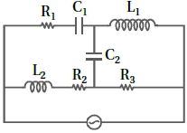
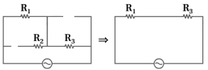
Difficult
Draw the effective equivalent circuit of the circuit shown in the figure at very high frequencies and find the effective impedance.
Solution
(N/A) The inductive reactance is given by $X_{L} = 2 \pi \nu L$ and the capacitive reactance is given by $X_{C} = \frac{1}{2 \pi \nu C}$.
For very high frequencies,$\nu \rightarrow \infty$.
As $\nu \rightarrow \infty$,the inductive reactance $X_{L} \rightarrow \infty$,which acts as an open circuit. Conversely,the capacitive reactance $X_{C} \rightarrow 0$,which acts as a short circuit.
Therefore,in the given circuit,the capacitors $C_{1}$ and $C_{2}$ behave as short circuits (wires),and the inductors $L_{1}$ and $L_{2}$ behave as open circuits (breaks in the path).
By replacing the components with their high-frequency equivalents,the circuit simplifies to a series combination of resistors $R_{1}$ and $R_{3}$.
Thus,the effective impedance is $Z_{eq} = R_{1} + R_{3}$.
0 likes
View Solution131
Medium
$A$ coil of $0.01 \, H$ inductance and $1 \, \Omega$ resistance is connected to a $200 \, V, 50 \, Hz$ $AC$ supply. Find the impedance of the circuit and the time lag between the maximum alternating voltage and current.
Solution
(A) Given: Inductance $L = 0.01 \, H$,Resistance $R = 1 \, \Omega$,Voltage $V = 200 \, V$,Frequency $f = 50 \, Hz$.
$1$. Calculate the inductive reactance $X_L$:
$X_L = 2 \pi f L = 2 \times 3.1416 \times 50 \times 0.01 = 3.1416 \, \Omega$.
$2$. Calculate the impedance $Z$:
$Z = \sqrt{R^2 + X_L^2} = \sqrt{1^2 + (3.1416)^2} = \sqrt{1 + 9.8696} = \sqrt{10.8696} \approx 3.297 \, \Omega$.
$3$. Calculate the phase angle $\phi$:
$\tan \phi = \frac{X_L}{R} = \frac{3.1416}{1} = 3.1416$.
$\phi = \tan^{-1}(3.1416) \approx 72.34^{\circ}$.
$4$. Calculate the time lag $\Delta t$:
$\Delta t = \frac{\phi}{\omega} = \frac{\phi}{2 \pi f} = \frac{72.34 \times \pi / 180}{2 \times \pi \times 50} = \frac{72.34}{36000} \approx 0.00201 \, s$ or $2.01 \, ms$.
0 likes
View Solution132
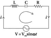
Medium
For an $LCR$ circuit driven at frequency $\omega $,the equation reads $L\frac{di}{dt} + Ri + \frac{q}{C} = V_i = V_m \sin \omega t$.
$(a)$ Multiply the equation by $i$ and simplify where possible.
$(b)$ Interpret each term physically.
$(c)$ Cast the equation in the form of a conservation of energy statement.
$(d)$ Integrate the equation over one cycle to find that the phase difference between $V$ and $i$ must be acute.
$(a)$ Multiply the equation by $i$ and simplify where possible.
$(b)$ Interpret each term physically.
$(c)$ Cast the equation in the form of a conservation of energy statement.
$(d)$ Integrate the equation over one cycle to find that the phase difference between $V$ and $i$ must be acute.
Solution
(N/A) The given equation for an $LCR$ circuit is:
$L \frac{di}{dt} + Ri + \frac{q}{C} = V_m \sin \omega t$
$(a)$ Multiplying by $i$ on both sides:
$Li \frac{di}{dt} + i^2 R + \frac{q}{C} i = V_m i \sin \omega t$
Since $i = \frac{dq}{dt}$,we can write:
$\frac{d}{dt} \left( \frac{1}{2} L i^2 \right) + i^2 R + \frac{d}{dt} \left( \frac{q^2}{2C} \right) = Vi$
$(b)$ Physical interpretation:
$Li \frac{di}{dt} = \frac{d}{dt} (\frac{1}{2} L i^2)$ is the rate of change of magnetic energy stored in the inductor.
$i^2 R$ is the rate of Joule heating (power dissipation) in the resistor.
$\frac{q}{C} i = \frac{d}{dt} (\frac{q^2}{2C})$ is the rate of change of electric energy stored in the capacitor.
$Vi$ is the instantaneous power supplied by the source.
$(c)$ The equation $\frac{d}{dt} (\frac{1}{2} L i^2 + \frac{q^2}{2C}) + i^2 R = Vi$ represents the conservation of energy,where the power supplied by the source equals the sum of the rate of change of stored energy and the power dissipated as heat.
$(d)$ Integrating over one cycle $T = \frac{2\pi}{\omega}$:
$\int_0^T \frac{d}{dt} (\frac{1}{2} L i^2 + \frac{q^2}{2C}) dt + \int_0^T i^2 R dt = \int_0^T Vi dt$
Since the energy stored in $L$ and $C$ is periodic,the integral of the derivative over one cycle is zero.
$0 + I_{rms}^2 R T = \int_0^T Vi dt$
Since $I_{rms}^2 R T > 0$,the average power $\int_0^T Vi dt$ must be positive. This implies $\cos \phi > 0$,meaning the phase difference $\phi$ must be acute.
0 likes
View Solution133
DifficultMCQ
An inductance coil has a reactance of $100\, \Omega$. When an $AC$ signal of frequency $1000\, Hz$ is applied to the coil,the applied voltage leads the current by $45^{\circ}$. The self-inductance of the coil is
A
$1.1 \times 10^{-2}\; H$
B
$1.1 \times 10^{-1} \;H$
C
$5.5 \times 10^{-5} \;H$
D
$6.7 \times 10^{-7}\; H$
Solution
(A) The impedance $Z$ of an $RL$ circuit is given by $Z = \sqrt{R^2 + X_L^2} = 100\, \Omega$.
Given that the voltage leads the current by $\phi = 45^{\circ}$,we have $\tan \phi = \frac{X_L}{R}$.
Since $\tan 45^{\circ} = 1$,it follows that $X_L = R$.
Substituting $X_L = R$ into the impedance equation: $\sqrt{X_L^2 + X_L^2} = 100 \Rightarrow \sqrt{2} X_L = 100$.
Thus,$X_L = \frac{100}{\sqrt{2}} = 50\sqrt{2}\, \Omega$.
Since $X_L = 2\pi f L$,we have $L = \frac{X_L}{2\pi f} = \frac{50\sqrt{2}}{2 \times \pi \times 1000}$.
$L = \frac{25\sqrt{2}}{1000\pi} \approx \frac{25 \times 1.414}{3141.59} \approx 0.01125\, H = 1.125 \times 10^{-2}\, H$.
0 likes
View Solution134
MediumMCQ
$A$ light bulb and an inductor coil are connected to an $AC$ source through a key as shown in the figure below. The key is closed and after some time an iron rod is inserted into the interior of the inductor. The glow of the light bulb
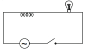
A
increases
B
decreases
C
remains unchanged
D
will fluctuate
Solution
(B) When an iron rod is inserted into the inductor,its self-inductance $L$ increases because the permeability of the core increases.
The inductive reactance is given by $X_L = \omega L$. As $L$ increases,$X_L$ also increases.
The impedance of the circuit is $Z = \sqrt{R^2 + X_L^2}$. Since $X_L$ increases,the total impedance $Z$ of the circuit increases.
The current in the circuit is given by $I = \frac{V}{Z}$. As $Z$ increases,the current $I$ flowing through the circuit decreases.
The power dissipated in the bulb is given by $P = I^2 R$. Since the current $I$ decreases,the power dissipated in the bulb decreases,and therefore,the glow of the light bulb decreases.
0 likes
View Solution135
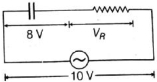
MediumMCQ
In a series $R-C$ circuit shown in the figure,the applied voltage is $10\, V$ and the voltage across the capacitor is found to be $8\, V$. Then,the voltage across $R$ and the phase difference between the current and the applied voltage will respectively be
A
$6\, V, \tan^{-1}\left(\frac{4}{3}\right)$
B
$3\, V, \tan^{-1}\left(\frac{3}{4}\right)$
C
$6\, V, \tan^{-1}\left(\frac{5}{3}\right)$
D
None of these
Solution
(A) For a series $R-C$ circuit,the total applied voltage $V$ is given by the phasor sum of the voltage across the resistor $V_R$ and the voltage across the capacitor $V_C$:
$V^2 = V_R^2 + V_C^2$
Given $V = 10\, V$ and $V_C = 8\, V$,we have:
$10^2 = V_R^2 + 8^2$
$100 = V_R^2 + 64$
$V_R^2 = 100 - 64 = 36$
$V_R = 6\, V$
Now,the phase difference $\phi$ between the current and the applied voltage is given by:
$\tan \phi = \frac{V_C}{V_R}$
$\tan \phi = \frac{8}{6} = \frac{4}{3}$
$\phi = \tan^{-1}\left(\frac{4}{3}\right)$
Thus,the voltage across $R$ is $6\, V$ and the phase difference is $\tan^{-1}\left(\frac{4}{3}\right)$.
0 likes
View Solution136
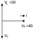
MediumMCQ
In an $LCR$ series circuit,the source voltage is $120 \ V$,the voltage across the inductor is $50 \ V$,and the voltage across the resistor is $40 \ V$. Determine the voltage across the capacitor.
A
$V_{C}=10(5-8\sqrt{2}) \ V$
B
$V_{C}=10(5+8\sqrt{2}) \ V$
C
$V_{C}=20(5+8\sqrt{2}) \ V$
D
$V_{C}=10(5+7\sqrt{2}) \ V$
Solution
(B) In an $LCR$ series circuit,the relationship between the source voltage $V$ and the voltages across the components is given by:
$V^{2} = V_{R}^{2} + (V_{L} - V_{C})^{2}$
Given:
$V = 120 \ V$
$V_{R} = 40 \ V$
$V_{L} = 50 \ V$
Substituting the values into the equation:
$120^{2} = 40^{2} + (50 - V_{C})^{2}$
$14400 = 1600 + (50 - V_{C})^{2}$
$(50 - V_{C})^{2} = 14400 - 1600 = 12800$
Taking the square root on both sides:
$50 - V_{C} = \pm \sqrt{12800} = \pm \sqrt{6400 \times 2} = \pm 80\sqrt{2}$
Case $1$: $50 - V_{C} = 80\sqrt{2} \implies V_{C} = 50 - 80\sqrt{2}$ (Negative value,not possible for magnitude)
Case $2$: $50 - V_{C} = -80\sqrt{2} \implies V_{C} = 50 + 80\sqrt{2}$
$V_{C} = 10(5 + 8\sqrt{2}) \ V$
0 likes
View Solution137
MediumMCQ
Match List-$I$ with List-$II$:
Choose the most appropriate answer from the options given below:
| List-$I$ | List-$II$ |
|---|---|
| $(a)$ Phase difference between current and voltage in a purely resistive $AC$ circuit | $(i)$ $\frac{\pi}{2}$; current leads voltage |
| $(b)$ Phase difference between current and voltage in a pure inductive $AC$ circuit | $(ii)$ zero |
| $(c)$ Phase difference between current and voltage in a pure capacitive $AC$ circuit | $(iii)$ $\frac{\pi}{2}$; current lags voltage |
| $(d)$ Phase difference between current and voltage in an $LCR$ series circuit | $(iv)$ $\tan^{-1}\left(\frac{X_C - X_L}{R}\right)$ |
Choose the most appropriate answer from the options given below:
A
$(a)-(i), (b)-(iii), (c)-(iv), (d)-(ii)$
B
$(a)-(ii), (b)-(iv), (c)-(iii), (d)-(i)$
C
$(a)-(ii), (b)-(iii), (c)-(iv), (d)-(i)$
D
$(a)-(ii), (b)-(iii), (c)-(i), (d)-(iv)$
Solution
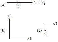
(D) The phase difference $\phi$ between voltage and current is defined as follows:
$(a)$ In a purely resistive circuit,voltage and current are in the same phase,so the phase difference is $0$.
$(b)$ In a pure inductive circuit,voltage leads current by $\frac{\pi}{2}$,which means current lags voltage by $\frac{\pi}{2}$.
$(c)$ In a pure capacitive circuit,current leads voltage by $\frac{\pi}{2}$.
$(d)$ In an $LCR$ series circuit,the phase difference is given by $\tan \phi = \frac{X_L - X_C}{R}$,or equivalently $\tan \phi = \frac{-(X_C - X_L)}{R}$,which corresponds to $\tan^{-1}\left(\frac{X_C - X_L}{R}\right)$ depending on the sign convention.
Comparing these,we get $(a)-(ii), (b)-(iii), (c)-(i), (d)-(iv)$.
0 likes
View Solution138
MediumMCQ
An $AC$ circuit has an inductor and a resistor of resistance $R$ in series,such that $X_L = 3R$. Now,a capacitor is added in series such that $X_C = 2R$. The ratio of the new power factor to the old power factor of the circuit is $\sqrt{5} : x$. The value of $x$ is ...... .
A
$2$
B
$1$
C
$3$
D
$4$
Solution
(B) The power factor of an $AC$ circuit is given by $\cos \phi = \frac{R}{Z}$.
For the initial circuit ($RL$ circuit):
$Z = \sqrt{R^2 + X_L^2} = \sqrt{R^2 + (3R)^2} = \sqrt{R^2 + 9R^2} = \sqrt{10R^2} = R\sqrt{10}$.
Old power factor,$\cos \phi = \frac{R}{R\sqrt{10}} = \frac{1}{\sqrt{10}}$.
For the new circuit ($RLC$ circuit):
$Z' = \sqrt{R^2 + (X_L - X_C)^2} = \sqrt{R^2 + (3R - 2R)^2} = \sqrt{R^2 + R^2} = \sqrt{2R^2} = R\sqrt{2}$.
New power factor,$\cos \phi' = \frac{R}{R\sqrt{2}} = \frac{1}{\sqrt{2}}$.
The ratio of the new power factor to the old power factor is:
$\frac{\cos \phi'}{\cos \phi} = \frac{1/\sqrt{2}}{1/\sqrt{10}} = \frac{\sqrt{10}}{\sqrt{2}} = \sqrt{5} = \frac{\sqrt{5}}{1}$.
Comparing this with $\sqrt{5} : x$,we get $x = 1$.
0 likes
View Solution139
DifficultMCQ
In an $LCR$ series circuit,an inductor $30 \, {mH}$ and a resistor $1 \, \Omega$ are connected to an $AC$ source of angular frequency $300 \, {rad/s}$. The value of capacitance for which the current leads the voltage by $45^{\circ}$ is $\frac{1}{x} \times 10^{-3} \, {F}$. Then the value of $x$ is ..... .
A
$3$
B
$5$
C
$7$
D
$9$
Solution
(A) The phase angle $\phi$ in an $LCR$ circuit is given by $\tan \phi = \frac{X_C - X_L}{R}$.
Since the current leads the voltage,the circuit is capacitive,and the phase angle is $\phi = -45^{\circ}$.
Thus,$\tan(-45^{\circ}) = \frac{X_C - X_L}{R} \implies -1 = \frac{X_C - X_L}{R}$.
This gives $X_L - X_C = R$.
Given $L = 30 \, {mH} = 0.03 \, {H}$,$R = 1 \, \Omega$,and $\omega = 300 \, {rad/s}$.
$X_L = \omega L = 300 \times 0.03 = 9 \, \Omega$.
Substituting the values: $9 - X_C = 1 \implies X_C = 8 \, \Omega$.
Since $X_C = \frac{1}{\omega C}$,we have $\frac{1}{300 \times C} = 8$.
$C = \frac{1}{300 \times 8} = \frac{1}{2400} = \frac{1}{2.4} \times 10^{-3} \, {F}$.
Wait,re-evaluating the phase condition: If current leads voltage,$\phi$ is negative,so $\tan \phi = \frac{X_C - X_L}{R} = \tan(-45^{\circ}) = -1$.
$X_L - X_C = R \implies 9 - X_C = 1 \implies X_C = 8$. This leads to $C = \frac{1}{2400} \approx 0.416 \times 10^{-3} \, {F}$.
If the question implies the magnitude of the phase difference is $45^{\circ}$ and current leads,then $X_C > X_L$ is incorrect; it should be $X_L - X_C = R$ if current lags. For current to lead,$X_C - X_L = R$ is not possible if $X_C < X_L$. Let's re-check: $\tan \phi = \frac{X_L - X_C}{R}$. For current to lead,$\phi$ must be negative,so $\frac{X_C - X_L}{R} = \tan(45^{\circ}) = 1$ is wrong. The correct relation is $\tan \phi = \frac{X_L - X_C}{R}$. For current to lead,$\phi = -45^{\circ}$,so $-1 = \frac{X_L - X_C}{R} \implies X_C - X_L = R$.
$X_C - 9 = 1 \implies X_C = 10 \, \Omega$.
$\frac{1}{300 \times C} = 10 \implies C = \frac{1}{3000} = \frac{1}{3} \times 10^{-3} \, {F}$.
Thus,$x = 3$.
0 likes
View Solution140
MediumMCQ
For a series $LCR$ circuit with $R=100\,\Omega$,$L=0.5\,mH$ and $C=0.1\,pF$ connected across $220\,V-50\,Hz$ $AC$ supply,the phase angle between current and supplied voltage and the nature of the circuit is:
A
$\approx 90^{\circ}$,predominantly inductive circuit
B
$0^{\circ}$,resistive circuit
C
$0^{\circ}$,resonance circuit
D
$\approx 90^{\circ}$,predominantly capacitive circuit
Solution
(D) Given: $R=100\,\Omega$,$L=0.5\,mH = 0.5 \times 10^{-3}\,H$,$C=0.1\,pF = 0.1 \times 10^{-12}\,F$,$f=50\,Hz$.
Angular frequency $\omega = 2\pi f = 2\pi \times 50 = 100\pi\,rad/s$.
Inductive reactance $X_L = \omega L = 100\pi \times 0.5 \times 10^{-3} = 0.05\pi\,\Omega \approx 0.157\,\Omega$.
Capacitive reactance $X_C = \frac{1}{\omega C} = \frac{1}{100\pi \times 0.1 \times 10^{-12}} = \frac{10^{11}}{10\pi} = \frac{10^{10}}{\pi}\,\Omega \approx 3.18 \times 10^9\,\Omega$.
Since $X_C \gg X_L$ and $X_C \gg R$,the circuit is predominantly capacitive.
The phase angle $\phi$ is given by $\tan \phi = \frac{X_L - X_C}{R}$.
Since $X_C$ is extremely large compared to $R$ and $X_L$,$\tan \phi \approx -\infty$,which implies $\phi \approx -90^{\circ}$.
The negative sign indicates that the current leads the voltage by approximately $90^{\circ}$,confirming the circuit is predominantly capacitive.
0 likes
View Solution141
DifficultMCQ
$A$ $0.07\,H$ inductor and a $12\,\Omega$ resistor are connected in series to a $220\,V, 50\,Hz$ $AC$ source. The approximate current in the circuit and the phase angle between current and source voltage are respectively. [Take $\pi$ as $\frac{22}{7}$]
A
$88\,A$ and $\tan^{-1}\left(\frac{11}{6}\right)$
B
$0.88\,A$ and $\tan^{-1}\left(\frac{11}{6}\right)$
C
$8.8\,A$ and $\tan^{-1}\left(\frac{11}{6}\right)$
D
$8.8\,A$ and $\tan^{-1}\left(\frac{6}{11}\right)$
Solution
(C) Inductive reactance,$X_L = \omega L = 2\pi f L$.
Substituting the values,$X_L = 2 \times \frac{22}{7} \times 50 \times 0.07 = 100 \times \frac{22}{7} \times 0.07 = 22\,\Omega$.
Impedance of the circuit,$Z = \sqrt{R^2 + X_L^2} = \sqrt{12^2 + 22^2} = \sqrt{144 + 484} = \sqrt{628} \approx 25.06\,\Omega \approx 25\,\Omega$.
Current in the circuit,$I = \frac{V}{Z} = \frac{220}{25} = 8.8\,A$.
Phase angle $\phi$ is given by $\tan \phi = \frac{X_L}{R} = \frac{22}{12} = \frac{11}{6}$.
Therefore,$\phi = \tan^{-1}\left(\frac{11}{6}\right)$.
0 likes
View Solution142
DifficultMCQ
$A$ sinusoidal voltage $V(t) = 210 \sin(3000t) \text{ V}$ is applied to a series $LCR$ circuit in which $L = 10 \text{ mH}$,$C = 25 \mu\text{F}$,and $R = 100 \Omega$. The phase difference $(\Phi)$ between the applied voltage and resultant current will be
A
$\tan^{-1}(0.17)$
B
$\tan^{-1}(9.46)$
C
$\tan^{-1}(0.30)$
D
$\tan^{-1}(13.33)$
Solution
(A) Given: $V(t) = 210 \sin(3000t) \text{ V}$,$L = 10 \text{ mH} = 10^{-2} \text{ H}$,$C = 25 \mu\text{F} = 25 \times 10^{-6} \text{ F}$,$R = 100 \Omega$.
Angular frequency $\omega = 3000 \text{ rad/s}$.
Inductive reactance $X_L = \omega L = 3000 \times 10^{-2} = 30 \Omega$.
Capacitive reactance $X_C = \frac{1}{\omega C} = \frac{1}{3000 \times 25 \times 10^{-6}} = \frac{1}{0.075} = \frac{1000}{75} = \frac{40}{3} \Omega \approx 13.33 \Omega$.
The phase difference $\Phi$ is given by $\tan \Phi = \frac{X_L - X_C}{R}$.
$\tan \Phi = \frac{30 - 13.33}{100} = \frac{16.67}{100} = 0.1667 \approx 0.17$.
Therefore,$\Phi = \tan^{-1}(0.17)$.
0 likes
View Solution143
DifficultMCQ
To light a $50\,W, 100\,V$ lamp,it is connected in series with a capacitor of capacitance $C = \frac{50}{\pi \sqrt{x}} \mu F$ to a $200\,V, 50\,Hz$ $AC$ source. The value of $x$ is........
A
$2$
B
$3$
C
$1$
D
$8$
Solution
(B) The resistance of the lamp is $R = \frac{V_L^2}{P} = \frac{100^2}{50} = 200\,\Omega$.
In an $RC$ series circuit,the total voltage $V$ is given by $V^2 = V_R^2 + V_C^2$,where $V_R = 100\,V$ is the voltage across the lamp.
$200^2 = 100^2 + V_C^2 \Rightarrow V_C^2 = 40000 - 10000 = 30000 \Rightarrow V_C = 100\sqrt{3}\,V$.
The current in the circuit is $I = \frac{V_R}{R} = \frac{100}{200} = 0.5\,A$.
The capacitive reactance is $X_C = \frac{V_C}{I} = \frac{100\sqrt{3}}{0.5} = 200\sqrt{3}\,\Omega$.
Since $X_C = \frac{1}{2\pi f C}$,we have $200\sqrt{3} = \frac{1}{2 \times \pi \times 50 \times C} \Rightarrow C = \frac{1}{200\sqrt{3} \times 100\pi} = \frac{1}{20000\pi\sqrt{3}}\,F$.
Converting to $\mu F$: $C = \frac{10^6}{20000\pi\sqrt{3}} = \frac{50}{\pi\sqrt{3}}\,\mu F$.
Comparing this with $C = \frac{50}{\pi\sqrt{x}}\,\mu F$,we get $x = 3$.
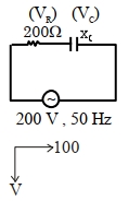
0 likes
View Solution144
MediumMCQ
$A$ circuit element $X$ when connected to an a.c. supply of peak voltage $100\,V$ gives a peak current of $5\,A$ which is in phase with the voltage. $A$ second element $Y$ when connected to the same a.c. supply also gives the same value of peak current which lags behind the voltage by $\frac{\pi}{2}$. If $X$ and $Y$ are connected in series to the same supply,what will be the rms value of the current in ampere?
A
$\frac{10}{\sqrt{2}}$
B
$\frac{5}{\sqrt{2}}$
C
$5 \sqrt{2}$
D
$\frac{5}{2}$
Solution
(D) For element $X$,the current is in phase with the voltage,so $X$ is a resistor.
The resistance $R = \frac{V_0}{I_0} = \frac{100}{5} = 20\,\Omega$.
For element $Y$,the current lags behind the voltage by $\frac{\pi}{2}$,so $Y$ is an inductor.
The inductive reactance $X_L = \frac{V_0}{I_0} = \frac{100}{5} = 20\,\Omega$.
When $X$ and $Y$ are connected in series,the total impedance $Z = \sqrt{R^2 + X_L^2} = \sqrt{20^2 + 20^2} = 20\sqrt{2}\,\Omega$.
The peak current in the series circuit is $I_0 = \frac{V_0}{Z} = \frac{100}{20\sqrt{2}} = \frac{5}{\sqrt{2}}\,A$.
The rms current is $I_{rms} = \frac{I_0}{\sqrt{2}} = \frac{5/\sqrt{2}}{\sqrt{2}} = \frac{5}{2}\,A$.
0 likes
View Solution145
EasyMCQ
In a series $RLC$ circuit,the potential differences across $R, L$ and $C$ are $30 \,V, 60 \,V$ and $100 \,V$ respectively,as shown in the figure. The $e.m.f.$ of the source (in volts) is:
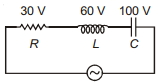
A
$190$
B
$70$
C
$50$
D
$40$
Solution
(C) In a series $RLC$ circuit,the total voltage (source $e.m.f.$) is given by the phasor sum of the individual potential differences:
$V_{source} = \sqrt{V_R^2 + (V_L - V_C)^2}$
Given:
$V_R = 30 \,V$
$V_L = 60 \,V$
$V_C = 100 \,V$
Substituting these values into the formula:
$V_{source} = \sqrt{(30)^2 + (60 - 100)^2}$
$V_{source} = \sqrt{(30)^2 + (-40)^2}$
$V_{source} = \sqrt{900 + 1600}$
$V_{source} = \sqrt{2500} = 50 \,V$
Thus,the $e.m.f.$ of the source is $50 \,V$.
0 likes
View Solution146
MediumMCQ
In a series $L-C$ circuit,if $L=10^{-3} \,H$ and $C=3 \times 10^{-7} \,F$ is connected to a $100 \,V, 50 \,Hz$ a.c. source,the impedance of the circuit is ...........
A
$\frac{10^5}{3 \pi}-10 \pi$
B
$0.1 \pi-3 \times 10^{-5} \pi$
C
$\frac{10^5}{3 \pi}-\frac{\pi}{10}$
D
None of these
Solution
(C) Given: $L = 10^{-3} \,H$,$C = 3 \times 10^{-7} \,F$,$f = 50 \,Hz$.
Angular frequency $\omega = 2 \pi f = 2 \pi \times 50 = 100 \pi \,rad/s$.
Inductive reactance $X_L = \omega L = (100 \pi) \times 10^{-3} = 0.1 \pi \, \Omega$.
Capacitive reactance $X_C = \frac{1}{\omega C} = \frac{1}{100 \pi \times 3 \times 10^{-7}} = \frac{10^7}{300 \pi} = \frac{10^5}{3 \pi} \, \Omega$.
Since it is a series $L-C$ circuit,the impedance $Z = |X_L - X_C|$.
$Z = |0.1 \pi - \frac{10^5}{3 \pi}|$.
Since $\frac{10^5}{3 \pi} \approx 10610 \, \Omega$ and $0.1 \pi \approx 0.314 \, \Omega$,the impedance is $Z = \frac{10^5}{3 \pi} - 0.1 \pi = \frac{10^5}{3 \pi} - \frac{\pi}{10} \, \Omega$.
0 likes
View Solution147
MediumMCQ
An electric bulb rated $100 \,W - 300 \,V$ is connected to an $AC$ supply of $500 \,V$ and $\frac{150}{\pi} \,Hz$. The required inductance to save the electric bulb is .......... $H$.
A
$2$
B
$\frac{1}{2}$
C
$4$
D
$\frac{1}{4}$
Solution
(C) The bulb is rated $P = 100 \,W$ and $V_b = 300 \,V$.
The current through the bulb is $I = \frac{P}{V_b} = \frac{100}{300} = \frac{1}{3} \,A$.
The resistance of the bulb is $R = \frac{V_b^2}{P} = \frac{300^2}{100} = 900 \,\Omega$.
When connected to a $V = 500 \,V$ supply,the total impedance $Z$ is given by $Z = \frac{V}{I} = \frac{500}{1/3} = 1500 \,\Omega$.
In an $LR$ circuit,$Z^2 = R^2 + X_L^2$,so $X_L^2 = Z^2 - R^2$.
$X_L^2 = 1500^2 - 900^2 = (1500 - 900)(1500 + 900) = 600 \times 2400 = 1440000$.
$X_L = \sqrt{1440000} = 1200 \,\Omega$.
Since $X_L = 2 \pi f L$,we have $1200 = 2 \pi \left(\frac{150}{\pi}\right) L$.
$1200 = 300 L$,which gives $L = 4 \,H$.
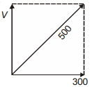
0 likes
View Solution148
EasyMCQ
$A$ sinusoidal voltage of peak value $283\,V$ and frequency $50\,Hz$ is applied to a series $LCR$ circuit in which $R = 3\,\Omega$,$L = 25.48\,mH$,and $C = 796\,\mu F$. Find the impedance of the circuit in $\Omega$.
A
$5$
B
$12$
C
$18$
D
$22$
Solution
(A) Given: $R = 3\,\Omega$,$L = 25.48\,mH = 25.48 \times 10^{-3}\,H$,$C = 796\,\mu F = 796 \times 10^{-6}\,F$,and $f = 50\,Hz$.
First,calculate the inductive reactance $X_L$:
$X_L = 2\pi f L = 2 \times 3.14 \times 50 \times 25.48 \times 10^{-3} \approx 8\,\Omega$.
Next,calculate the capacitive reactance $X_C$:
$X_C = \frac{1}{2\pi f C} = \frac{1}{2 \times 3.14 \times 50 \times 796 \times 10^{-6}} \approx 4\,\Omega$.
The impedance $Z$ of the series $LCR$ circuit is given by:
$Z = \sqrt{R^2 + (X_L - X_C)^2}$.
Substituting the values:
$Z = \sqrt{3^2 + (8 - 4)^2} = \sqrt{9 + 4^2} = \sqrt{9 + 16} = \sqrt{25} = 5\,\Omega$.
0 likes
View Solution149
MediumMCQ
$A$ resistance of $400\,\Omega$ is connected in series with an inductor of $(3/\pi)\,H$ and this combination is connected across an $A.C.$ source as shown in the figure,where $e = 400 \sin(100\pi t)$. Which of the following statements is correct?
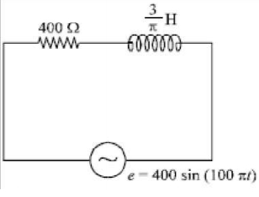
A
In the circuit,the peak value of current is $(5/4)\,A$.
B
In the circuit,the potential difference across the resistance is in the same phase as the current.
C
In the circuit,the potential difference across the inductor is $53^{\circ}$ leading the current.
D
In the circuit,the potential difference across the inductor is $37^{\circ}$ leading the current.
Solution
(B) Given: $R = 400\,\Omega$,$L = (3/\pi)\,H$,$e = 400 \sin(100\pi t)$.
Comparing with $e = E_0 \sin(\omega t)$,we get $E_0 = 400\,V$ and $\omega = 100\pi\,rad/s$.
Inductive reactance $X_L = \omega L = 100\pi \times (3/\pi) = 300\,\Omega$.
Impedance $Z = \sqrt{R^2 + X_L^2} = \sqrt{400^2 + 300^2} = 500\,\Omega$.
Peak current $I_0 = E_0 / Z = 400 / 500 = 0.8\,A = (4/5)\,A$. Thus,option $(a)$ is incorrect.
In a series $RL$ circuit,the potential difference across the resistor is always in phase with the current. Thus,option $(b)$ is correct.
The potential difference across an inductor always leads the current by $90^{\circ}$. Thus,options $(c)$ and $(d)$ are incorrect.
0 likes
View SolutionAlternating Current — RL, RC and LC AC Circuits · Frequently Asked Questions
1Are these Alternating Current questions useful for JEE and NEET?
Yes. All questions in this section are mapped to JEE Main and NEET exam patterns. Previous year questions from JEE Main, NEET, GUJCET and state-level exams are included with full solutions.
2Can I switch to Hindi or Gujarati for these questions?
Yes. Use the language tabs in the hero section or the sidebar to view the same questions and solutions in English, Hindi or Gujarati.
3How do I generate a question paper from this subtopic?
Use the Vedclass Exam Paper Generator — select the chapter and subtopic, set difficulty, and generate Sets A, B, C, D automatically. First 3 chapters of every subject are free.
Vedclass Products
For Students
Vedclass Test Series
Mock tests in real JEE/NEET style with performance analysis. 5-day free trial.
Start Free TrialFor Teachers
Exam Paper Generator
Generate Set A/B/C/D papers from this chapter in 2 minutes. 3 chapters free.
Try FreeFor Institutes
Online Exam Module
Live online exams with unlimited students, 360° analytics & white-label branding.
See DemoFor Teachers & Institutes
Generate a Alternating Current Exam Paper in 2 Minutes
Select subtopic & difficulty — Sets A, B, C, D auto-generated with No Repeat logic.
First 3 chapters of every subject are free — no payment required.