
A English
Inductance, Capacitance and Resistance in Series and Parallel Questions in English
Class 12 Physics · Alternating Current · Inductance, Capacitance and Resistance in Series and Parallel
138+
Questions
English
Language
100%
With Solutions
Showing 50 of 138 questions in English
1
EasyMCQ
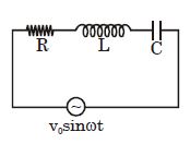
In an $LCR$ circuit,the capacitance is changed from $C$ to $4C$. For the same resonant frequency,the inductance should be changed from $L$ to:
A
$2L$
B
$L/2$
C
$L/4$
D
$4L$
Solution
(C) The resonant frequency of an $LCR$ circuit is given by the formula $\omega = \frac{1}{\sqrt{LC}}$.
Since the resonant frequency remains the same,we have $\omega_1 = \omega_2$.
Therefore,$\frac{1}{\sqrt{L_1 C_1}} = \frac{1}{\sqrt{L_2 C_2}}$.
Squaring both sides,we get $L_1 C_1 = L_2 C_2$.
Given $L_1 = L$,$C_1 = C$,and $C_2 = 4C$,we substitute these values into the equation:
$L \cdot C = L_2 \cdot (4C)$.
Solving for $L_2$,we get $L_2 = \frac{L \cdot C}{4C} = \frac{L}{4}$.
0 likes
View Solution2
MediumMCQ
If a resistance of $100\, \Omega$,an inductance of $0.5\, H$,and a capacitance of $10 \times 10^{-6}\, F$ are connected in series to a $50\, Hz$ $AC$ supply,then the impedance is:
A
$1.876\, \Omega$
B
$18.76\, \Omega$
C
$189.72\, \Omega$
D
$101.3\, \Omega$
Solution
(C) The impedance $Z$ of an $LCR$ series circuit is given by $Z = \sqrt{R^2 + (X_L - X_C)^2}$.
Given: $R = 100\, \Omega$,$L = 0.5\, H$,$C = 10 \times 10^{-6}\, F$,and $f = 50\, Hz$.
Angular frequency $\omega = 2\pi f = 2 \times \pi \times 50 = 100\pi\, rad/s$.
Inductive reactance $X_L = \omega L = 100\pi \times 0.5 = 50\pi \approx 157.08\, \Omega$.
Capacitive reactance $X_C = \frac{1}{\omega C} = \frac{1}{100\pi \times 10 \times 10^{-6}} = \frac{1}{10^{-3}\pi} = \frac{1000}{\pi} \approx 318.31\, \Omega$.
Now,$Z = \sqrt{100^2 + (157.08 - 318.31)^2} = \sqrt{10000 + (-161.23)^2} = \sqrt{10000 + 25995.11} = \sqrt{35995.11} \approx 189.72\, \Omega$.
0 likes
View Solution3
MediumMCQ
In a series $R-L-C$ circuit,$R = 300 \, \Omega$,$L = 0.9 \, H$,$C = 2.0 \, \mu F$,and $\omega = 1000 \, rad/s$. The impedance of the circuit is ........ $\Omega$.
A
$1300$
B
$900$
C
$500$
D
$400$
Solution
(C) The impedance $Z$ of a series $R-L-C$ circuit is given by the formula: $Z = \sqrt{R^2 + (X_L - X_C)^2}$.
First,calculate the inductive reactance $X_L = \omega L = 1000 \times 0.9 = 900 \, \Omega$.
Next,calculate the capacitive reactance $X_C = \frac{1}{\omega C} = \frac{1}{1000 \times 2.0 \times 10^{-6}} = \frac{10^6}{2000} = 500 \, \Omega$.
Now,substitute these values into the impedance formula:
$Z = \sqrt{300^2 + (900 - 500)^2}$
$Z = \sqrt{300^2 + 400^2}$
$Z = \sqrt{90000 + 160000} = \sqrt{250000} = 500 \, \Omega$.
0 likes
View Solution4
EasyMCQ
In a series resonant circuit,the $ac$ voltage across resistance $R$,inductance $L$,and capacitance $C$ are $5\, V$,$10\, V$,and $10\, V$ respectively. The $ac$ voltage applied to the circuit will be.....$V$.
A
$20$
B
$10$
C
$5$
D
$25$
Solution
(C) In a series $LCR$ circuit,the total applied voltage $V$ is given by the phasor sum of the voltages across the individual components:
$V = \sqrt{V_R^2 + (V_L - V_C)^2}$
Given:
$V_R = 5\, V$
$V_L = 10\, V$
$V_C = 10\, V$
Substituting these values into the formula:
$V = \sqrt{5^2 + (10 - 10)^2}$
$V = \sqrt{25 + 0^2}$
$V = \sqrt{25} = 5\, V$
Therefore,the applied $ac$ voltage is $5\, V$.
$V = \sqrt{V_R^2 + (V_L - V_C)^2}$
Given:
$V_R = 5\, V$
$V_L = 10\, V$
$V_C = 10\, V$
Substituting these values into the formula:
$V = \sqrt{5^2 + (10 - 10)^2}$
$V = \sqrt{25 + 0^2}$
$V = \sqrt{25} = 5\, V$
Therefore,the applied $ac$ voltage is $5\, V$.
0 likes
View Solution5
EasyMCQ
For a series $LCR$ circuit,which of the following statements is wrong?
A
Applied e.m.f. and potential difference across resistance are in the same phase.
B
Applied e.m.f. and potential difference across the inductor coil have a phase difference of $\pi / 2$.
C
Potential difference across the capacitor and inductor have a phase difference of $\pi / 2$.
D
Potential difference across resistance and capacitor have a phase difference of $\pi / 2$.
Solution
(C) In a series $LCR$ circuit,the current $I$ is the same through all components.
$1$. The potential difference across the resistor $(V_R)$ is in phase with the current.
$2$. The potential difference across the inductor $(V_L)$ leads the current by $\pi / 2$.
$3$. The potential difference across the capacitor $(V_C)$ lags behind the current by $\pi / 2$.
$4$. Therefore,the phase difference between $V_L$ and $V_C$ is $\pi / 2 - (-\pi / 2) = \pi$.
Thus,the statement that the potential difference across the capacitor and inductor have a phase difference of $\pi / 2$ is incorrect.
0 likes
View Solution6
MediumMCQ
$A$ circuit has a resistance of $11\,\Omega$,an inductive reactance of $25\,\Omega$,and a capacitive reactance of $18\,\Omega$. It is connected to an $AC$ source of $260\,V$ and $50\,Hz$. The current through the circuit (in amperes) is:
A
$11$
B
$15$
C
$18$
D
$20$
Solution
(D) The impedance $Z$ of an $LCR$ series circuit is given by $Z = \sqrt{R^2 + (X_L - X_C)^2}$.
Given: $R = 11\,\Omega$,$X_L = 25\,\Omega$,$X_C = 18\,\Omega$.
Substituting the values: $Z = \sqrt{11^2 + (25 - 18)^2} = \sqrt{121 + 7^2} = \sqrt{121 + 49} = \sqrt{170}$.
Wait,recalculating: $Z = \sqrt{121 + 49} = \sqrt{170} \approx 13.03\,\Omega$. Given the options,let's re-verify the values: $11^2 = 121$,$(25-18)^2 = 7^2 = 49$. $121+49 = 170$. If $R=12$,$Z = \sqrt{144+49} = \sqrt{193}$. If $R=12$ and $X_L-X_C=5$,$Z=13$. Assuming the intended calculation was $Z = \sqrt{12^2 + 5^2} = 13$,but based on the provided values $R=11, X_L=25, X_C=18$,$Z = \sqrt{170} \approx 13.03$. Using $Z \approx 13\,\Omega$,the current $I = V/Z = 260/13 = 20\,A$.
0 likes
View Solution7
EasyMCQ
In an $LCR$ circuit,the potential difference between the terminals of the inductor is $60\,V$,between the terminals of the capacitor is $30\,V$,and between the terminals of the resistor is $40\,V$. The supply voltage will be equal to ......$V$.
A
$50$
B
$70$
C
$130$
D
$10$
Solution
(A) In a series $LCR$ circuit,the supply voltage $V$ is given by the phasor sum of the individual potential differences across the components.
The formula is: $V = \sqrt{V_R^2 + (V_L - V_C)^2}$
Given:
$V_L = 60\,V$
$V_C = 30\,V$
$V_R = 40\,V$
Substituting the values:
$V = \sqrt{40^2 + (60 - 30)^2}$
$V = \sqrt{1600 + 30^2}$
$V = \sqrt{1600 + 900}$
$V = \sqrt{2500}$
$V = 50\,V$
Therefore,the supply voltage is $50\,V$.
The formula is: $V = \sqrt{V_R^2 + (V_L - V_C)^2}$
Given:
$V_L = 60\,V$
$V_C = 30\,V$
$V_R = 40\,V$
Substituting the values:
$V = \sqrt{40^2 + (60 - 30)^2}$
$V = \sqrt{1600 + 30^2}$
$V = \sqrt{1600 + 900}$
$V = \sqrt{2500}$
$V = 50\,V$
Therefore,the supply voltage is $50\,V$.
0 likes
View Solution8
EasyMCQ
In an $LCR$ series $ac$ circuit,the voltage across each of the components,$L, C$ and $R$ is $50\,V$. The voltage across the $LC$ combination will be........$V$.
A
$50$
B
$50\sqrt{2}$
C
$100$
D
$0$
Solution
(D) In an $LCR$ series $ac$ circuit,the voltage across the inductor $(V_L)$ and the voltage across the capacitor $(V_C)$ are $180^{\circ}$ out of phase with each other.
Given that $V_L = 50\,V$ and $V_C = 50\,V$.
The net voltage across the $LC$ combination is given by the phasor sum: $V_{LC} = |V_L - V_C|$.
Substituting the values: $V_{LC} = |50\,V - 50\,V| = 0\,V$.
Therefore,the voltage across the $LC$ combination is $0\,V$.
Given that $V_L = 50\,V$ and $V_C = 50\,V$.
The net voltage across the $LC$ combination is given by the phasor sum: $V_{LC} = |V_L - V_C|$.
Substituting the values: $V_{LC} = |50\,V - 50\,V| = 0\,V$.
Therefore,the voltage across the $LC$ combination is $0\,V$.
0 likes
View Solution9
MediumMCQ
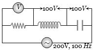
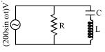
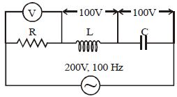
In the circuit given below,what will be the reading of the voltmeter $V$ (in $V$)?
A
$300$
B
$900$
C
$200$
D
$400$
Solution
(C) The circuit is an $LCR$ series circuit connected to an $AC$ source of $200 \ V$.
From the diagram,the voltage across the inductor is $V_L = 100 \ V$ and the voltage across the capacitor is $V_C = 100 \ V$.
The total voltage $V_{total}$ in an $LCR$ series circuit is given by the formula:
$V_{total}^2 = V_R^2 + (V_L - V_C)^2$
Given $V_{total} = 200 \ V$,$V_L = 100 \ V$,and $V_C = 100 \ V$.
Substituting these values:
$(200)^2 = V_R^2 + (100 - 100)^2$
$40000 = V_R^2 + 0$
$V_R = 200 \ V$
The voltmeter $V$ is connected across the resistor,so its reading is equal to $V_R$.
Therefore,the reading of the voltmeter is $200 \ V$.
0 likes
View Solution10
DifficultMCQ
An $LCR$ series circuit with a resistance of $100 \, \Omega$ is connected to an $ac$ source of $200 \, V \, (r.m.s.)$ and angular frequency $300 \, rad/s$. When only the capacitor is removed, the current lags behind the voltage by $60^o$. When only the inductor is removed, the current leads the voltage by $60^o$. The average power dissipated is.....$W$
A
$50$
B
$100$
C
$200$
D
$400$
Solution
(D) In an $LCR$ series circuit, when the capacitor is removed, the circuit becomes an $LR$ circuit. The phase angle is given by $\tan \phi = \frac{X_L}{R}$. Given $\phi = 60^o$, we have $\tan 60^o = \frac{X_L}{R} \Rightarrow X_L = R \sqrt{3}$.
When the inductor is removed, the circuit becomes an $RC$ circuit. The phase angle is given by $\tan \phi = \frac{X_C}{R}$. Given $\phi = 60^o$, we have $\tan 60^o = \frac{X_C}{R} \Rightarrow X_C = R \sqrt{3}$.
Since $X_L = X_C$, the circuit is in resonance when both components are present.
At resonance, the impedance $Z = R = 100 \, \Omega$.
The average power dissipated is $P = \frac{V^2}{R} = \frac{200^2}{100} = \frac{40000}{100} = 400 \, W$.
0 likes
View Solution11
DifficultMCQ
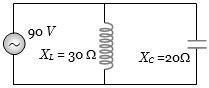
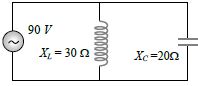
In the adjoining figure,the impedance of the circuit will be $... \Omega$.
A
$120$
B
$50$
C
$60$
D
$90$
Solution
(C) The circuit consists of an inductor with inductive reactance $X_L = 30 \, \Omega$ and a capacitor with capacitive reactance $X_C = 20 \, \Omega$ connected in parallel to an $AC$ source of $V = 90 \, V$.
The current through the inductor is $i_L = \frac{V}{X_L} = \frac{90}{30} = 3 \, A$.
The current through the capacitor is $i_C = \frac{V}{X_C} = \frac{90}{20} = 4.5 \, A$.
Since the current in the inductor lags the voltage by $90^\circ$ and the current in the capacitor leads the voltage by $90^\circ$,the currents are in opposite phases.
The net current through the circuit is $i = |i_C - i_L| = |4.5 - 3| = 1.5 \, A$.
The impedance of the circuit is $Z = \frac{V}{i} = \frac{90}{1.5} = 60 \, \Omega$.
0 likes
View Solution12
MediumMCQ
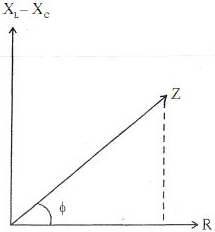
Which one of the following curves represents the variation of impedance $(Z)$ with frequency $(f)$ in a series $LCR$ circuit?
A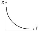
B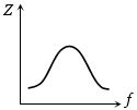
C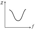
D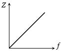
Solution
(C) The impedance $(Z)$ of a series $LCR$ circuit is given by the formula:
$Z = \sqrt{R^2 + \left( 2\pi fL - \frac{1}{2\pi fC} \right)^2}$
$1$. At low frequencies $(f \to 0)$,the capacitive reactance $X_C = \frac{1}{2\pi fC}$ becomes very large,so $Z \to \infty$.
$2$. At the resonant frequency $f_r = \frac{1}{2\pi \sqrt{LC}}$,the inductive reactance $X_L = 2\pi fL$ equals the capacitive reactance $X_C$,making the term $(X_L - X_C) = 0$. Thus,the impedance reaches its minimum value,$Z = R$.
$3$. At high frequencies $(f > f_r)$,the inductive reactance $X_L = 2\pi fL$ becomes very large,causing $Z$ to increase again.
Therefore,the graph of $Z$ versus $f$ starts from a high value,decreases to a minimum at $f_r$,and then increases. This behavior is correctly represented by graph $C$.
0 likes
View Solution13
DifficultMCQ
In an $LCR$ circuit,$R = 100 \ \Omega$. When the capacitor $C$ is removed,the current lags behind the voltage by a phase of $\pi / 3$. When the inductor $L$ is removed,the current leads the voltage by a phase of $\pi / 3$. What is the impedance of the circuit in $\Omega$?
A
$50$
B
$100$
C
$200$
D
$400$
Solution
(B) For the $RL$ circuit,the phase angle $\phi = \pi / 3$. The tangent of the phase angle is given by $\tan \phi = \frac{X_L}{R}$.
Thus,$\tan(\pi / 3) = \frac{X_L}{R} \implies \sqrt{3} = \frac{X_L}{100} \implies X_L = 100\sqrt{3} \ \Omega$.
For the $RC$ circuit,the phase angle $\phi = \pi / 3$. The tangent of the phase angle is given by $\tan \phi = \frac{X_C}{R}$.
Thus,$\tan(\pi / 3) = \frac{X_C}{R} \implies \sqrt{3} = \frac{X_C}{100} \implies X_C = 100\sqrt{3} \ \Omega$.
In the $LCR$ circuit,the impedance $Z$ is given by $Z = \sqrt{R^2 + (X_L - X_C)^2}$.
Since $X_L = X_C$,the term $(X_L - X_C) = 0$.
Therefore,$Z = \sqrt{R^2 + 0} = R = 100 \ \Omega$.
0 likes
View Solution14
DifficultMCQ
In an $LCR$ series circuit,if $R = X_L = 2X_C$,find the impedance and the phase difference between the current and the voltage.
A
$\frac{\sqrt{5}R}{2}, \tan^{-1}(2)$
B
$\frac{\sqrt{5}R}{2}, \tan^{-1}\left(\frac{1}{2}\right)$
C
$\sqrt{5}X_C, \tan^{-1}(2)$
D
$\sqrt{5}R, \tan^{-1}\left(\frac{1}{2}\right)$
Solution
(B) Given: $R = X_L$ and $R = 2X_C$,which implies $X_L = R$ and $X_C = \frac{R}{2}$.
The impedance $Z$ of an $LCR$ series circuit is given by $Z = \sqrt{R^2 + (X_L - X_C)^2}$.
Substituting the values: $Z = \sqrt{R^2 + (R - \frac{R}{2})^2} = \sqrt{R^2 + (\frac{R}{2})^2} = \sqrt{R^2 + \frac{R^2}{4}} = \sqrt{\frac{5R^2}{4}} = \frac{\sqrt{5}}{2}R$.
The phase difference $\phi$ is given by $\tan \phi = \frac{X_L - X_C}{R}$.
Substituting the values: $\tan \phi = \frac{R - \frac{R}{2}}{R} = \frac{R/2}{R} = \frac{1}{2}$.
Therefore,$\phi = \tan^{-1}(\frac{1}{2})$.
Thus,the impedance is $\frac{\sqrt{5}}{2}R$ and the phase difference is $\tan^{-1}(\frac{1}{2})$.
0 likes
View Solution15
DifficultMCQ
Find the impedance of the circuit in $\Omega$.
A
$120$
B
$50$
C
$60$
D
$90$
Solution
(C) The circuit consists of an inductor and a capacitor connected in parallel across an $AC$ source of $90 \; V$.
For the inductor branch,the current is $I_L = \frac{V}{X_L} = \frac{90}{30} = 3 \; A$.
For the capacitor branch,the current is $I_C = \frac{V}{X_C} = \frac{90}{20} = 4.5 \; A$.
Since the currents in the inductor and capacitor are $180^{\circ}$ out of phase,the total current $I$ drawn from the source is $I = |I_C - I_L| = |4.5 - 3| = 1.5 \; A$.
The impedance $Z$ of the parallel circuit is given by $Z = \frac{V}{I} = \frac{90}{1.5} = 60 \; \Omega$.
0 likes
View Solution16
MediumMCQ
When $L$, $C$, and $R$ are connected in series with an $AC$ source of frequency $f$, the current leads the voltage by a phase angle of $45^{\circ}$. What is the value of $C$?
A
$\frac{1}{2\pi f(2\pi fL + R)}$
B
$\frac{1}{\pi f(2\pi fL + R)}$
C
$\frac{1}{2\pi f(2\pi fL - R)}$
D
$\frac{1}{\pi f(2\pi fL - R)}$
Solution
(A) The phase angle $\phi$ in an $LCR$ series circuit is given by $\tan \phi = \frac{X_C - X_L}{R}$.
Since the current leads the voltage, the circuit is capacitive, meaning $X_C > X_L$. The phase angle is $\phi = 45^{\circ}$.
Substituting the values: $\tan 45^{\circ} = \frac{X_C - X_L}{R}$.
Since $\tan 45^{\circ} = 1$, we have $1 = \frac{\frac{1}{2\pi fC} - 2\pi fL}{R}$.
Rearranging the terms: $R = \frac{1}{2\pi fC} - 2\pi fL$.
$\frac{1}{2\pi fC} = 2\pi fL + R$.
Therefore, $C = \frac{1}{2\pi f(2\pi fL + R)}$.
0 likes
View Solution17
DifficultMCQ
In an electrical circuit,$R, L, C$ and an $AC$ voltage source are all connected in series. When $L$ is removed from the circuit,the phase difference between the voltage and the current in the circuit is $\pi / 3$. If instead,$C$ is removed from the circuit,the phase difference is again $\pi / 3$. The power factor of the circuit is
A
$1$
B
$\frac{1}{\sqrt{2}}$
C
$0.5$
D
$\frac{\sqrt{3}}{2}$
Solution
(A) When $L$ is removed,the circuit becomes an $RC$ circuit. The phase difference $\phi_1$ is given by $\tan \phi_1 = \frac{X_C}{R}$.
Given $\phi_1 = \pi / 3$,so $\tan(\pi / 3) = \frac{X_C}{R} \implies X_C = R \sqrt{3}$.
When $C$ is removed,the circuit becomes an $RL$ circuit. The phase difference $\phi_2$ is given by $\tan \phi_2 = \frac{X_L}{R}$.
Given $\phi_2 = \pi / 3$,so $\tan(\pi / 3) = \frac{X_L}{R} \implies X_L = R \sqrt{3}$.
Since $X_L = X_C$,the circuit is in resonance.
In a series $LCR$ circuit,the impedance $Z$ is given by $Z = \sqrt{R^2 + (X_L - X_C)^2}$.
Substituting $X_L = X_C$,we get $Z = \sqrt{R^2 + 0} = R$.
The power factor is $\cos \phi = \frac{R}{Z} = \frac{R}{R} = 1$.
0 likes
View Solution18
DifficultMCQ
An inductor $20 \, mH$,a capacitor $50 \, \mu F$ and a resistor $40 \, \Omega$ are connected in series across a source of emf $V = 10 \, \sin \, 340t$. The power loss in the $A.C.$ circuit is ...... $W$.
A
$0.67$
B
$0.76$
C
$0.89$
D
$0.46$
Solution
(D) Given: $L = 20 \, mH = 20 \times 10^{-3} \, H$,$C = 50 \, \mu F = 50 \times 10^{-6} \, F$,$R = 40 \, \Omega$,$V = 10 \, \sin \, 340t$.
Comparing with $V = V_0 \sin \omega t$,we get $V_0 = 10 \, V$ and $\omega = 340 \, rad/s$.
Inductive reactance $X_L = \omega L = 340 \times 20 \times 10^{-3} = 6.8 \, \Omega$.
Capacitive reactance $X_C = \frac{1}{\omega C} = \frac{1}{340 \times 50 \times 10^{-6}} = \frac{10^6}{17000} \approx 58.82 \, \Omega$.
Impedance $Z = \sqrt{R^2 + (X_C - X_L)^2} = \sqrt{40^2 + (58.82 - 6.8)^2} = \sqrt{1600 + (52.02)^2} = \sqrt{1600 + 2706.08} = \sqrt{4306.08} \approx 65.62 \, \Omega$.
Peak current $I_0 = \frac{V_0}{Z} = \frac{10}{65.62} \, A$.
Power factor $\cos \phi = \frac{R}{Z} = \frac{40}{65.62}$.
Power loss $P = V_{rms} I_{rms} \cos \phi = \frac{1}{2} V_0 I_0 \cos \phi = \frac{1}{2} \times 10 \times \frac{10}{65.62} \times \frac{40}{65.62} = \frac{2000}{4306} \approx 0.46 \, W$.
0 likes
View Solution19
MediumMCQ
In a radio receiver,the short wave and medium wave stations are tuned by using the same capacitor but coils of different inductance $L_s$ and $L_m$ respectively. Then:
A
$L_s > L_m$
B
$L_s < L_m$
C
$L_s = L_m$
D
None of these
Solution
(B) The resonant frequency of an $LC$ circuit is given by $\nu = \frac{1}{2\pi \sqrt{LC}}$.
Since the same capacitor $C$ is used for both,we have $\nu \propto \frac{1}{\sqrt{L}}$.
Short waves have shorter wavelengths $(\lambda_s < \lambda_m)$,which implies they have higher frequencies $(\nu_s > \nu_m)$ because $\nu = \frac{c}{\lambda}$.
Since $\nu_s > \nu_m$,it follows that $\frac{1}{\sqrt{L_s}} > \frac{1}{\sqrt{L_m}}$.
Squaring both sides and rearranging,we get $L_s < L_m$.
0 likes
View Solution20
MediumMCQ
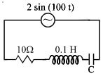
The power factor of the given $LCR$ circuit is $1/\sqrt{2}$. Find the capacitance $C$ of the circuit in $\mu F$.
A
$400$
B
$300$
C
$500$
D
$200$
Solution
(C) From the circuit diagram,we have resistance $R = 10 \ \Omega$,inductance $L = 0.1 \ H$,and angular frequency $\omega = 100 \ rad/s$.
The power factor is given by $\cos \phi = \frac{R}{Z} = \frac{R}{\sqrt{R^2 + (X_L - X_C)^2}} = \frac{1}{\sqrt{2}}$.
This implies $Z = R\sqrt{2}$,so $R^2 + (X_L - X_C)^2 = 2R^2$,which simplifies to $(X_L - X_C)^2 = R^2$.
Thus,$X_L - X_C = \pm R$.
Given $X_L = \omega L = 100 \times 0.1 = 10 \ \Omega$.
Case $1$: $10 - X_C = 10 \implies X_C = 0$ (not possible for finite $C$).
Case $2$: $10 - X_C = -10 \implies X_C = 20 \ \Omega$.
Since $X_C = \frac{1}{\omega C}$,we have $20 = \frac{1}{100 \times C}$.
$C = \frac{1}{2000} \ F = 0.5 \times 10^{-3} \ F = 500 \ \mu F$.
0 likes
View Solution21
MediumMCQ
The power factor of an $L-R$ series circuit is $0.6$ and that of a $C-R$ series circuit is $0.5$. If the elements ($L, C,$ and $R$) of the two circuits are joined in series,the power factor of this circuit is found to be $1$. The ratio of the resistance in the $L-R$ circuit to the resistance in the $C-R$ circuit is:
A
$6/5$
B
$5/6$
C
$\frac{4}{3\sqrt{3}}$
D
$\frac{3\sqrt{3}}{4}$
Solution
(D) For the $L-R$ circuit: $\cos \phi_1 = \frac{R_1}{Z_1} = 0.6 = \frac{3}{5}$. Thus,$\sin \phi_1 = \frac{X_L}{Z_1} = 0.8 = \frac{4}{5}$. So,$X_L = \frac{4}{3} R_1$.
For the $C-R$ circuit: $\cos \phi_2 = \frac{R_2}{Z_2} = 0.5 = \frac{1}{2}$. Thus,$\sin \phi_2 = \frac{X_C}{Z_2} = \frac{\sqrt{3}}{2}$. So,$X_C = \sqrt{3} R_2$.
When joined in series,the circuit becomes an $L-C-R$ circuit. For the power factor to be $1$,the circuit must be in resonance,meaning $X_L = X_C$.
Equating the reactances: $\frac{4}{3} R_1 = \sqrt{3} R_2$.
Therefore,the ratio $\frac{R_1}{R_2} = \frac{3\sqrt{3}}{4}$.
0 likes
View Solution22
DifficultMCQ
In the circuit diagram shown,$X_C = 100 \, \Omega$,$X_L = 200 \, \Omega$,and $R = 100 \, \Omega$. The source voltage is $V = 200 \sin(\omega t) \, \text{V}$. The effective $(RMS)$ current through the source is:
A
$2 \sqrt{2} \, \text{A}$
B
$\sqrt{2} \, \text{A}$
C
$0.5 \, \text{A}$
D
$2 \, \text{A}$
Solution
(D) The circuit consists of a resistor $R$ in parallel with a series combination of an inductor $L$ and a capacitor $C$.
The peak voltage is $V_0 = 200 \, \text{V}$. The $RMS$ voltage is $V_{\text{rms}} = \frac{V_0}{\sqrt{2}} = \frac{200}{\sqrt{2}} = 100\sqrt{2} \, \text{V}$.
The current through the resistor is $I_R = \frac{V_{\text{rms}}}{R} = \frac{100\sqrt{2}}{100} = \sqrt{2} \, \text{A}$.
The current through the $LC$ branch is $I_{LC} = \frac{V_{\text{rms}}}{|X_L - X_C|} = \frac{100\sqrt{2}}{|200 - 100|} = \frac{100\sqrt{2}}{100} = \sqrt{2} \, \text{A}$.
Since the current through the resistor is in phase with the voltage and the current through the $LC$ branch is $90^\circ$ out of phase with the voltage,the total $RMS$ current is given by $I_{\text{rms}} = \sqrt{I_R^2 + I_{LC}^2}$.
$I_{\text{rms}} = \sqrt{(\sqrt{2})^2 + (\sqrt{2})^2} = \sqrt{2 + 2} = \sqrt{4} = 2 \, \text{A}$.
0 likes
View Solution23
DifficultMCQ
In a series $LR$ circuit,$X_L = 3R$. Now,a capacitor with $X_C = R$ is added in series. What is the ratio of the new power factor to the old power factor?
A
$1$
B
$2$
C
$\frac{1}{\sqrt{2}}$
D
$\sqrt{2}$
Solution
(D) In the initial series $LR$ circuit,the impedance is $Z_1 = \sqrt{R^2 + X_L^2}$.
Given $X_L = 3R$,so $Z_1 = \sqrt{R^2 + (3R)^2} = \sqrt{10R^2} = R\sqrt{10}$.
The initial power factor is $\cos \phi_1 = \frac{R}{Z_1} = \frac{R}{R\sqrt{10}} = \frac{1}{\sqrt{10}}$.
When a capacitor with $X_C = R$ is added in series,the circuit becomes an $LCR$ circuit.
The new impedance is $Z_2 = \sqrt{R^2 + (X_L - X_C)^2}$.
Substituting the values,$Z_2 = \sqrt{R^2 + (3R - R)^2} = \sqrt{R^2 + (2R)^2} = \sqrt{5R^2} = R\sqrt{5}$.
The new power factor is $\cos \phi_2 = \frac{R}{Z_2} = \frac{R}{R\sqrt{5}} = \frac{1}{\sqrt{5}}$.
The ratio of the new power factor to the old power factor is $\frac{\cos \phi_2}{\cos \phi_1} = \frac{1/\sqrt{5}}{1/\sqrt{10}} = \frac{\sqrt{10}}{\sqrt{5}} = \sqrt{2}$.
0 likes
View Solution24
MediumMCQ
$A$ circuit has three elements: a resistance of $11 \Omega$,a coil of inductive reactance $120 \Omega$,and a capacitive reactance of $120 \Omega$ in series,connected to an $A.C.$ source of $110 \, V, 60 \, Hz$. Which of the three elements has the minimum potential difference?
A
Resistance
B
Capacitance
C
Inductor
D
All will have equal potential difference
Solution
(A) In a series $LCR$ circuit,the current $I$ is the same through all elements.
The potential difference across each element is given by $V_R = I \cdot R$,$V_L = I \cdot X_L$,and $V_C = I \cdot X_C$.
Given: $R = 11 \, \Omega$,$X_L = 120 \, \Omega$,$X_C = 120 \, \Omega$.
The total impedance $Z$ is $\sqrt{R^2 + (X_L - X_C)^2} = \sqrt{11^2 + (120 - 120)^2} = 11 \, \Omega$.
The current $I = V / Z = 110 / 11 = 10 \, A$.
Now,calculating potential differences:
$V_R = I \cdot R = 10 \times 11 = 110 \, V$.
$V_L = I \cdot X_L = 10 \times 120 = 1200 \, V$.
$V_C = I \cdot X_C = 10 \times 120 = 1200 \, V$.
Comparing the values,$V_R = 110 \, V$ is the minimum potential difference.
0 likes
View Solution25
MediumMCQ
$A$ series $LCR$ circuit containing a resistance of $120 \, \Omega$ has an angular resonance frequency of $4 \times 10^3 \, rad \, s^{-1}.$ At resonance, the voltages across the resistance and the inductance are $60 \, V$ and $40 \, V$ respectively. The values of $L$ and $C$ are respectively:
A
$20 \, mH, 25/8 \, \mu F$
B
$2 \, mH, 1/35 \, \mu F$
C
$20 \, mH, 1/40 \, \mu F$
D
$2 \, mH, 25/8 \, nF$
Solution
(A) At resonance, the current $I_{rms}$ in the circuit is given by $I_{rms} = \frac{V_R}{R} = \frac{60 \, V}{120 \, \Omega} = 0.5 \, A.$
The voltage across the inductor is $V_L = I_{rms} \times X_L = I_{rms} \times (\omega L).$
Substituting the values: $40 = 0.5 \times (4 \times 10^3) \times L.$
$40 = 2000 \times L \implies L = \frac{40}{2000} = 0.02 \, H = 20 \, mH.$
At resonance, the voltage across the capacitor $V_C$ is equal to the voltage across the inductor $V_L$, so $V_C = 40 \, V.$
$V_C = I_{rms} \times X_C = I_{rms} \times \left(\frac{1}{\omega C}\right).$
$40 = 0.5 \times \left(\frac{1}{4 \times 10^3 \times C}\right).$
$40 = \frac{0.5}{4000 \times C} \implies C = \frac{0.5}{4000 \times 40} = \frac{0.5}{160000} = \frac{5}{1600000} = \frac{1}{320000} \, F.$
$C = \frac{1}{320000} \times 10^6 \, \mu F = \frac{100}{32} \, \mu F = 3.125 \, \mu F = \frac{25}{8} \, \mu F.$
0 likes
View Solution26
DifficultMCQ
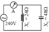
What is the reading in the $AC$ ammeter for the $AC$ circuit shown in the figure?
A
$2$
B
$2.4$
C
$5$
D
$10$
Solution
(C) The circuit consists of an inductor with inductive reactance $X_L = 24 \ \Omega$ and a capacitor with capacitive reactance $X_C = 48 \ \Omega$ connected in parallel to an $AC$ source of $V = 240 \ V$.
The current through the inductor is $I_L = \frac{V}{X_L} = \frac{240}{24} = 10 \ A$.
The current through the capacitor is $I_C = \frac{V}{X_C} = \frac{240}{48} = 5 \ A$.
In a parallel $LC$ circuit,the currents $I_L$ and $I_C$ are $180^{\circ}$ out of phase. Therefore,the total current $I$ measured by the ammeter is the magnitude of the difference between the two currents:
$I = |I_L - I_C| = |10 \ A - 5 \ A| = 5 \ A$.
0 likes
View Solution27
DifficultMCQ
For a series $LCR$ circuit,$R = X_L = 2X_C$. The impedance of the circuit and the phase difference between $V$ and $I$ respectively will be:
A
$\frac{\sqrt{5} R}{2}, \tan^{-1}(2)$
B
$\frac{\sqrt{5} R}{2}, \tan^{-1}(1/2)$
C
$\sqrt{5} X_C, \tan^{-1}(2)$
D
$\sqrt{5} R, \tan^{-1}(1/2)$
Solution
(B) Given: $R = X_L = 2X_C$.
From the given relation,we have $X_L = R$ and $X_C = R/2$.
The impedance $Z$ of a series $LCR$ circuit is given by:
$Z = \sqrt{R^2 + (X_L - X_C)^2}$
Substituting the values:
$Z = \sqrt{R^2 + (R - R/2)^2} = \sqrt{R^2 + (R/2)^2} = \sqrt{R^2 + R^2/4} = \sqrt{5R^2/4} = \frac{\sqrt{5}R}{2}$.
The phase difference $\phi$ is given by:
$\tan \phi = \frac{X_L - X_C}{R}$
Substituting the values:
$\tan \phi = \frac{R - R/2}{R} = \frac{R/2}{R} = 1/2$.
Therefore,$\phi = \tan^{-1}(1/2)$.
Thus,the impedance is $\frac{\sqrt{5}R}{2}$ and the phase difference is $\tan^{-1}(1/2)$.
0 likes
View Solution28
DifficultMCQ
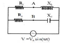
In a parallel $AC$ circuit with $R_1 = R_2 = R$ and $X_L = X_C = X$. An $AC$ source $V = V_0 \sin(\omega t)$ is connected across the circuit as shown in the figure. The $RMS$ value of the potential difference $V_A - V_B$ will be:
A
$\frac{\sqrt{2} V_0 R}{\sqrt{R^2 + X^2}}$
B
$\frac{V_0 R}{\sqrt{R^2 + X^2}}$
C
$\frac{2 V_0 R}{\sqrt{R^2 + X^2}}$
D
$\frac{\sqrt{2} V_0 X R}{R^2 + X^2}$
Solution
(D) The circuit consists of two parallel branches connected to an $AC$ source $V = V_0 \sin(\omega t)$.
Branch $1$ has $R$ and $X_L$ in series. The potential at point $A$ (relative to the bottom wire) is the voltage across the inductor: $V_A = V_0 \frac{X_L}{\sqrt{R^2 + X_L^2}} \sin(\omega t + \phi)$,where $\tan \phi = R/X_L$.
Branch $2$ has $R$ and $X_C$ in series. The potential at point $B$ (relative to the bottom wire) is the voltage across the capacitor: $V_B = V_0 \frac{X_C}{\sqrt{R^2 + X_C^2}} \sin(\omega t - \phi)$,where $\tan \phi = R/X_C$.
Given $R_1 = R_2 = R$ and $X_L = X_C = X$,let $Z = \sqrt{R^2 + X^2}$. Then $V_A = \frac{V_0 X}{Z} \sin(\omega t + \phi)$ and $V_B = \frac{V_0 X}{Z} \sin(\omega t - \phi)$.
The potential difference $V_A - V_B = \frac{V_0 X}{Z} [\sin(\omega t + \phi) - \sin(\omega t - \phi)] = \frac{V_0 X}{Z} [2 \cos(\omega t) \sin(\phi)]$.
Since $\sin \phi = R/Z$,we have $V_A - V_B = \frac{V_0 X}{Z} [2 \cos(\omega t) \frac{R}{Z}] = \frac{2 V_0 X R}{Z^2} \cos(\omega t) = \frac{2 V_0 X R}{R^2 + X^2} \cos(\omega t)$.
The peak value is $V_{peak} = \frac{2 V_0 X R}{R^2 + X^2}$. The $RMS$ value is $V_{RMS} = \frac{V_{peak}}{\sqrt{2}} = \frac{\sqrt{2} V_0 X R}{R^2 + X^2}$.
0 likes
View Solution29
MediumMCQ
In the $RLC$ series circuit as shown in the diagram,the maximum value of charge on the capacitor is:
A
$\frac{V_0}{\omega Z}$
B
$\frac{V_0 R}{\omega Z^2}$
C
$\frac{V_0 \omega}{Z}$
D
$\frac{V_0 \omega R}{Z^2}$
Solution
(A) The maximum current in an $RLC$ series circuit is given by $I_0 = \frac{V_0}{Z}$,where $Z$ is the impedance of the circuit.
The current in the circuit is $i(t) = I_0 \sin(\omega t - \phi)$.
The charge on the capacitor $q(t)$ is related to the current $i(t)$ by $i = \frac{dq}{dt}$.
Integrating the current,we get $q(t) = \int i(t) dt = \int I_0 \sin(\omega t - \phi) dt = -\frac{I_0}{\omega} \cos(\omega t - \phi)$.
The maximum charge $Q_0$ on the capacitor is the amplitude of this expression:
$Q_0 = \frac{I_0}{\omega}$.
Substituting $I_0 = \frac{V_0}{Z}$,we get:
$Q_0 = \frac{V_0}{\omega Z}$.
0 likes
View Solution30
MediumMCQ
$A$ series $R-L-C$ circuit consists of an $8.0\ \Omega$ resistor,a $5.0\ \mu F$ capacitor,and a $50.0\ mH$ inductor. $A$ variable frequency source applies an $emf$ of $400\ V\ (rms)$ across the combination. The power delivered to the circuit when the frequency is equal to one-half the resonance frequency is.....$W$
A
$52$
B
$57$
C
$63$
D
$69$
Solution
(B) Given: $R = 8.0\ \Omega$,$C = 5.0\ \mu F = 5.0 \times 10^{-6}\ F$,$L = 50.0\ mH = 50.0 \times 10^{-3}\ H$.
Resonance frequency $\omega_0 = \frac{1}{\sqrt{LC}} = \frac{1}{\sqrt{50 \times 10^{-3} \times 5 \times 10^{-6}}} = \frac{1}{\sqrt{250 \times 10^{-9}}} = \frac{1}{\sqrt{2.5 \times 10^{-7}}} = 2000\ rad/s$.
The operating frequency is $\omega = \frac{1}{2} \omega_0 = 1000\ rad/s$.
Inductive reactance $X_L = \omega L = 1000 \times 50 \times 10^{-3} = 50\ \Omega$.
Capacitive reactance $X_C = \frac{1}{\omega C} = \frac{1}{1000 \times 5 \times 10^{-6}} = \frac{1}{0.005} = 200\ \Omega$.
Impedance $Z = \sqrt{R^2 + (X_L - X_C)^2} = \sqrt{8^2 + (50 - 200)^2} = \sqrt{64 + (-150)^2} = \sqrt{64 + 22500} = \sqrt{22564} \approx 150.21\ \Omega$.
$I_{rms} = \frac{V_{rms}}{Z} = \frac{400}{150.21} \approx 2.663\ A$.
Power $P = I_{rms}^2 R = (2.663)^2 \times 8 \approx 7.09 \times 8 \approx 56.72\ W$.
Rounding to the nearest integer,$P \approx 57\ W$.
0 likes
View Solution31
MediumMCQ
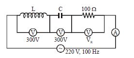
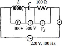
In the $LCR$ circuit shown in the figure,what will be the readings of the voltmeter across the resistor $(V_R)$ and the ammeter $(A)$ if an a.c. source of $220 \ V$ and $100 \ Hz$ is connected to it?
A
$300 \ V, 3 \ A$
B
$800 \ V, 8 \ A$
C
$110 \ V, 1.1 \ A$
D
$220 \ V, 2.2 \ A$
Solution
(D) In a series $LCR$ circuit,the total voltage $V$ is given by $V = \sqrt{V_R^2 + (V_L - V_C)^2}$.
Given: $V = 220 \ V$,$V_L = 300 \ V$,$V_C = 300 \ V$.
Substituting these values into the formula: $220 = \sqrt{V_R^2 + (300 - 300)^2}$.
$220 = \sqrt{V_R^2 + 0^2} = V_R$.
Thus,the reading of the voltmeter across the resistor is $V_R = 220 \ V$.
The current $I$ in the circuit is given by $I = \frac{V_R}{R}$.
Given $R = 100 \ \Omega$,we have $I = \frac{220 \ V}{100 \ \Omega} = 2.2 \ A$.
Therefore,the readings are $220 \ V$ and $2.2 \ A$.
0 likes
View Solution32
MediumMCQ
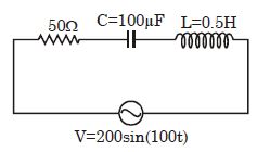
In the given $LCR$ $AC$ circuit,the effective current flowing through the circuit will be:
A
$2 \, A$
B
$2\sqrt{2} \, A$
C
$4 \, A$
D
$4\sqrt{2} \, A$
Solution
(A) From the given circuit,the voltage is $V = 200 \sin(100t) \, V$. Comparing this with $V = V_m \sin(\omega t)$,we get $V_m = 200 \, V$ and $\omega = 100 \, rad/s$.
The $RMS$ voltage is $V_{\text{rms}} = \frac{V_m}{\sqrt{2}} = \frac{200}{\sqrt{2}} = 100\sqrt{2} \, V$.
The circuit components are $R = 50 \, \Omega$,$L = 0.5 \, H$,and $C = 100 \, \mu F = 100 \times 10^{-6} \, F$.
Inductive reactance $X_L = \omega L = 100 \times 0.5 = 50 \, \Omega$.
Capacitive reactance $X_C = \frac{1}{\omega C} = \frac{1}{100 \times 100 \times 10^{-6}} = \frac{1}{0.01} = 100 \, \Omega$.
The impedance $Z$ of the $LCR$ circuit is given by $Z = \sqrt{R^2 + (X_L - X_C)^2}$.
$Z = \sqrt{50^2 + (50 - 100)^2} = \sqrt{50^2 + (-50)^2} = \sqrt{2500 + 2500} = \sqrt{5000} = 50\sqrt{2} \, \Omega$.
The effective $(RMS)$ current is $I_{\text{rms}} = \frac{V_{\text{rms}}}{Z} = \frac{100\sqrt{2}}{50\sqrt{2}} = 2 \, A$.
0 likes
View Solution33
MediumMCQ
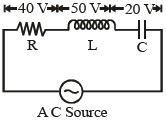
In a series $LCR$ circuit,the voltages across $R, L$ and $C$ are shown in the figure. The voltage of the applied source is ........ $V$. (in $, V$)
A
$110$
B
$10$
C
$50$
D
$70$
Solution
(C) In a series $LCR$ circuit,the total applied voltage $V$ is given by the phasor sum of the individual voltages across the resistor $(V_R)$,inductor $(V_L)$,and capacitor $(V_C)$.
The formula is: $V = \sqrt{V_R^2 + (V_L - V_C)^2}$
Given values from the figure:
$V_R = 40 \, V$
$V_L = 50 \, V$
$V_C = 20 \, V$
Substituting these values into the formula:
$V = \sqrt{(40)^2 + (50 - 20)^2}$
$V = \sqrt{40^2 + 30^2}$
$V = \sqrt{1600 + 900}$
$V = \sqrt{2500}$
$V = 50 \, V$
Therefore,the voltage of the applied source is $50 \, V$.
0 likes
View Solution34
EasyMCQ
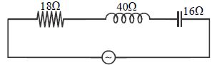
The impedance of the given circuit is......$\Omega $
A
$30$
B
$42$
C
$74$
D
$2\sqrt{417}$
Solution
(A) The circuit is a series $LCR$ circuit with resistance $R = 18 \ \Omega$,inductive reactance $X_L = 40 \ \Omega$,and capacitive reactance $X_C = 16 \ \Omega$.
The formula for the impedance $Z$ of a series $LCR$ circuit is given by:
$Z = \sqrt{R^2 + (X_L - X_C)^2}$
Substituting the given values:
$Z = \sqrt{18^2 + (40 - 16)^2}$
$Z = \sqrt{18^2 + 24^2}$
$Z = \sqrt{324 + 576}$
$Z = \sqrt{900}$
$Z = 30 \ \Omega$
Therefore,the impedance of the circuit is $30 \ \Omega$.
0 likes
View Solution35
DifficultMCQ
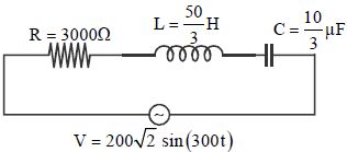
The average power consumed by the given circuit is $W$.
A
$9.6$
B
$4.8$
C
$26.66$
D
$13.33$
Solution
(B) From the given circuit,the voltage is $V = 200\sqrt{2} \sin(300t)$,so the $RMS$ voltage is $V_{rms} = 200 \, V$ and angular frequency $\omega = 300 \, rad/s$.
Given $R = 3000 \, \Omega$,$L = \frac{50}{3} \, H$,and $C = \frac{10}{3} \, \mu F = \frac{10}{3} \times 10^{-6} \, F$.
Inductive reactance $X_{L} = \omega L = 300 \times \frac{50}{3} = 5000 \, \Omega$.
Capacitive reactance $X_{C} = \frac{1}{\omega C} = \frac{1}{300 \times \frac{10}{3} \times 10^{-6}} = \frac{1}{10^{-3}} = 1000 \, \Omega$.
Impedance $Z = \sqrt{R^{2} + (X_{L} - X_{C})^{2}} = \sqrt{3000^{2} + (5000 - 1000)^{2}} = \sqrt{3000^{2} + 4000^{2}} = 5000 \, \Omega$.
The average power consumed is $P = I_{rms}^{2} R = \left(\frac{V_{rms}}{Z}\right)^{2} R$.
$P = \left(\frac{200}{5000}\right)^{2} \times 3000 = \left(\frac{1}{25}\right)^{2} \times 3000 = \frac{3000}{625} = 4.8 \, W$.
0 likes
View Solution36
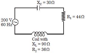
MediumMCQ
As shown in the figure,a series circuit connected across a $200 \,V, 60 \,Hz$ line consists of a capacitor of capacitive reactance $X_C = 30 \,\Omega$,a non-inductive resistor of $R_1 = 44 \,\Omega$,and a coil of inductive reactance $X_L = 90 \,\Omega$ and resistance $R_2 = 36 \,\Omega$. The power dissipated in the coil is.....$W$
A
$320$
B
$176$
C
$144$
D
$0$
Solution
(C) The total resistance of the circuit is $R_{total} = R_1 + R_2 = 44 \,\Omega + 36 \,\Omega = 80 \,\Omega$.
The total reactance of the circuit is $X_{total} = X_L - X_C = 90 \,\Omega - 30 \,\Omega = 60 \,\Omega$.
The impedance of the circuit is $Z = \sqrt{R_{total}^2 + X_{total}^2} = \sqrt{80^2 + 60^2} = \sqrt{6400 + 3600} = \sqrt{10000} = 100 \,\Omega$.
The $RMS$ current in the circuit is $I_{rms} = \frac{V_{rms}}{Z} = \frac{200 \,V}{100 \,\Omega} = 2 \,A$.
The power dissipated in the coil is given by $P_{coil} = I_{rms}^2 \times R_2$.
Substituting the values,$P_{coil} = (2 \,A)^2 \times 36 \,\Omega = 4 \times 36 = 144 \,W$.
0 likes
View Solution37
MediumMCQ
Power dissipated in an $LCR$ series circuit connected to an $a.c.$ source of electromotive force (emf) $\varepsilon$ is:
A
$\frac{\varepsilon^2 R}{\sqrt{R^2 + (L\omega - \frac{1}{C\omega})^2}}$
B
$\frac{\varepsilon^2 R}{R^2 + (L\omega - \frac{1}{C\omega})^2}$
C
$\frac{\varepsilon^2 \sqrt{R^2 + (L\omega - \frac{1}{C\omega})^2}}{R}$
D
$\frac{\varepsilon^2 (R^2 + (L\omega - \frac{1}{C\omega})^2)}{R}$
Solution
(B) The average power dissipated in an $a.c.$ circuit is given by $P = V_{rms} I_{rms} \cos \phi$.
Here,$V_{rms} = \varepsilon$ and $I_{rms} = \frac{\varepsilon}{Z}$,where $Z$ is the impedance of the $LCR$ circuit.
The power factor is $\cos \phi = \frac{R}{Z}$.
Substituting these into the power formula:
$P = \varepsilon \cdot \left( \frac{\varepsilon}{Z} \right) \cdot \left( \frac{R}{Z} \right) = \frac{\varepsilon^2 R}{Z^2}$.
The impedance $Z$ of an $LCR$ series circuit is $Z = \sqrt{R^2 + (L\omega - \frac{1}{C\omega})^2}$.
Therefore,$Z^2 = R^2 + (L\omega - \frac{1}{C\omega})^2$.
Substituting $Z^2$ into the power equation,we get:
$P = \frac{\varepsilon^2 R}{R^2 + (L\omega - \frac{1}{C\omega})^2}$.
0 likes
View Solution38
MediumMCQ
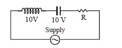
In the given series $LCR$ circuit,if the value of $R$ is changed,then:
A
voltage across $L$ remains same
B
voltage across $C$ remains same
C
voltage across $L-C$ combination remains same
D
voltage across $L-C$ combination changes
Solution
(C) In a series $LCR$ circuit,the current $I$ is given by $I = \frac{V}{\sqrt{R^2 + (X_L - X_C)^2}}$.
From the circuit diagram,the voltage across the inductor $V_L = 10 \text{ V}$ and the voltage across the capacitor $V_C = 10 \text{ V}$.
Since $V_L = V_C$,the circuit is in resonance,meaning $X_L = X_C$.
The voltage across the $L-C$ combination is $V_{LC} = |V_L - V_C|$.
Since $V_L = V_C = 10 \text{ V}$,$V_{LC} = |10 - 10| = 0 \text{ V}$.
If the resistance $R$ is changed,the current $I$ in the circuit changes.
However,the condition for resonance $(X_L = X_C)$ depends only on the frequency of the source and the values of $L$ and $C$,not on $R$.
Therefore,$V_L = I X_L$ and $V_C = I X_C$ will change as $I$ changes,but their difference $V_{LC} = I(X_L - X_C)$ will remain $0 \text{ V}$ because $X_L - X_C = 0$.
Thus,the voltage across the $L-C$ combination remains the same (zero).
0 likes
View Solution39
DifficultMCQ
An $LCR$ series circuit with $R = 100\,\Omega$ is connected to a $200\,V, 50\,Hz$ $a.c.$ source. When only the capacitance is removed,the current lags the voltage by $60^o$. When only the inductance is removed,the current leads the voltage by $60^o$. The current in the circuit is.....$A$
A
$2$
B
$1$
C
$\frac{\sqrt{3}}{2}$
D
$\frac{2}{\sqrt{3}}$
Solution
(A) Given: $R = 100\,\Omega$,$V = 200\,V$.
When capacitance is removed,the circuit becomes an $LR$ series circuit. The phase angle $\phi = 60^o$ is given by $\tan(60^o) = \frac{X_L}{R}$.
Thus,$X_L = R \tan(60^o) = 100 \times \sqrt{3} = 100\sqrt{3}\,\Omega$.
When inductance is removed,the circuit becomes an $RC$ series circuit. The phase angle $\phi = 60^o$ is given by $\tan(60^o) = \frac{X_C}{R}$.
Thus,$X_C = R \tan(60^o) = 100 \times \sqrt{3} = 100\sqrt{3}\,\Omega$.
In the original $LCR$ circuit,the impedance $Z = \sqrt{R^2 + (X_L - X_C)^2}$.
Since $X_L = X_C$,$Z = \sqrt{R^2 + 0} = R = 100\,\Omega$.
The current in the circuit is $I = \frac{V}{Z} = \frac{200}{100} = 2\,A$.
0 likes
View Solution40
DifficultMCQ
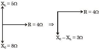
In a given series $LCR$ circuit,$R = 4\,\Omega ,$ $X_L = 5\,\Omega $ and $X_C = 8\, \Omega ,$ the current:
A
Leads the voltage by $tan^{-1}(3/4)$
B
Leads the voltage by $tan^{-1}(5/8)$
C
Lags the voltage by $tan^{-1}(3/4)$
D
Lags the voltage by $tan^{-1}(5/8)$
Solution
(A) The phase angle $\phi$ in an $LCR$ circuit is given by the formula: $\tan \phi = \frac{X_C - X_L}{R}$.
Substituting the given values: $\tan \phi = \frac{8\,\Omega - 5\,\Omega}{4\,\Omega} = \frac{3\,\Omega}{4\,\Omega} = \frac{3}{4}$.
Therefore,$\phi = \tan^{-1}(3/4)$.
Since $X_C > X_L$,the circuit is capacitive in nature,which means the current leads the voltage by the phase angle $\phi$.
Substituting the given values: $\tan \phi = \frac{8\,\Omega - 5\,\Omega}{4\,\Omega} = \frac{3\,\Omega}{4\,\Omega} = \frac{3}{4}$.
Therefore,$\phi = \tan^{-1}(3/4)$.
Since $X_C > X_L$,the circuit is capacitive in nature,which means the current leads the voltage by the phase angle $\phi$.
0 likes
View Solution41
MediumMCQ
In the circuit shown in the figure,the $AC$ source provides a voltage $V = 20 \cos(2000t)$. Neglecting source resistance,the voltmeter and ammeter readings will be:
A
$0 \, V, 2.0 \, A$
B
$0 \, V, 1.4 \, A$
C
$5.6 \, V, 1.4 \, A$
D
$8 \, V, 2.0 \, A$
Solution
(C) The given voltage is $V = 20 \cos(2000t)$,so the peak voltage $V_0 = 20 \, V$. The $RMS$ voltage is $V_{rms} = \frac{V_0}{\sqrt{2}} = \frac{20}{\sqrt{2}} = 10\sqrt{2} \, V \approx 14.14 \, V$.
The angular frequency is $\omega = 2000 \, rad/s$. The inductive reactance is $X_L = \omega L = 2000 \times 5 \times 10^{-3} = 10 \, \Omega$. The capacitive reactance is $X_C = \frac{1}{\omega C} = \frac{1}{2000 \times 50 \times 10^{-6}} = 10 \, \Omega$.
Since $X_L = X_C$,the series $LC$ branch is in resonance. The impedance of the $LC$ branch is $Z_{LC} = \sqrt{R_{LC}^2 + (X_L - X_C)^2} = \sqrt{4^2 + 0^2} = 4 \, \Omega$.
The total impedance of the circuit is $Z = R_{total} + Z_{LC} = 6 \, \Omega + 4 \, \Omega = 10 \, \Omega$.
The $RMS$ current in the circuit is $I_{rms} = \frac{V_{rms}}{Z} = \frac{10\sqrt{2}}{10} = \sqrt{2} \approx 1.414 \, A$. Thus,the ammeter reading is $1.4 \, A$.
The voltmeter is connected across the $LC$ branch. The voltage across this branch is $V_{LC} = I_{rms} \times Z_{LC} = 1.414 \times 4 = 5.656 \, V \approx 5.6 \, V$.
0 likes
View Solution42
DifficultMCQ
When the $rms$ voltages $V_L, V_C$ and $V_R$ are measured respectively across the inductor $L$,the capacitor $C$ and the resistor $R$ in a series $LCR$ circuit connected to an $AC$ source,it is found that the ratio $V_L : V_C : V_R = 1 : 2 : 3$. If the $rms$ voltage of the $AC$ source is $100 \, V$,the $V_R$ is close to........$V$
A
$50$
B
$70$
C
$90$
D
$100$
Solution
(C) In a series $LCR$ circuit,the total $rms$ voltage $V$ is given by the relation: $V = \sqrt{V_R^2 + (V_L - V_C)^2}$.
Given the ratio $V_L : V_C : V_R = 1 : 2 : 3$,we can express these voltages in terms of a constant $x$ as $V_L = x$,$V_C = 2x$,and $V_R = 3x$.
Substituting these values into the formula for $V$:
$100 = \sqrt{(3x)^2 + (x - 2x)^2}$
$100 = \sqrt{9x^2 + (-x)^2}$
$100 = \sqrt{9x^2 + x^2}$
$100 = \sqrt{10x^2}$
$100 = x\sqrt{10}$
$x = \frac{100}{\sqrt{10}} = 10\sqrt{10} \approx 10 \times 3.162 = 31.62 \, V$.
Now,calculate $V_R$:
$V_R = 3x = 3 \times 31.62 = 94.86 \, V$.
Rounding to the nearest given option,$V_R$ is close to $90 \, V$.
0 likes
View Solution43
DifficultMCQ
$A$ series $LR$ circuit is connected to an ac source of frequency $\omega$ and the inductive reactance is equal to $2R$. $A$ capacitance of capacitive reactance equal to $R$ is added in series with $L$ and $R$. The ratio of the new power factor to the old one is
A
$\sqrt{\frac{2}{3}}$
B
$\sqrt{\frac{2}{5}}$
C
$\sqrt{\frac{3}{2}}$
D
$\sqrt{\frac{5}{2}}$
Solution
(D) The power factor of an $LR$ circuit is given by $\cos \phi = \frac{R}{Z} = \frac{R}{\sqrt{R^2 + X_L^2}}$.
Given $X_L = 2R$,the old power factor is $\cos \phi_1 = \frac{R}{\sqrt{R^2 + (2R)^2}} = \frac{R}{\sqrt{5R^2}} = \frac{1}{\sqrt{5}}$.
When a capacitor with $X_C = R$ is added in series,the new impedance $Z_{new} = \sqrt{R^2 + (X_L - X_C)^2}$.
Substituting the values,$Z_{new} = \sqrt{R^2 + (2R - R)^2} = \sqrt{R^2 + R^2} = \sqrt{2R^2} = R\sqrt{2}$.
The new power factor is $\cos \phi_2 = \frac{R}{Z_{new}} = \frac{R}{R\sqrt{2}} = \frac{1}{\sqrt{2}}$.
The ratio of the new power factor to the old one is $\frac{\cos \phi_2}{\cos \phi_1} = \frac{1/\sqrt{2}}{1/\sqrt{5}} = \sqrt{\frac{5}{2}}$.
0 likes
View Solution44
DifficultMCQ
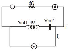
In an $LCR$ circuit shown in the following figure,what will be the readings of the voltmeter across the resistor and ammeter if an $a.c.$ source of $220\,V$ and $100\,Hz$ is connected to it as shown?
A
$800\,V, 8\,A$
B
$110\,V, 1.1\,A$
C
$300\,V, 3\,A$
D
$220\,V, 2.2\,A$
Solution
(D) In a series $LCR$ circuit,the total voltage $V$ is given by the relation:
$V = \sqrt{V_R^2 + (V_L - V_C)^2}$
Given from the figure:
$V = 220\,V$
$V_L = 300\,V$
$V_C = 300\,V$
Substituting these values into the equation:
$220 = \sqrt{V_R^2 + (300 - 300)^2}$
$220 = \sqrt{V_R^2 + 0^2}$
$V_R = 220\,V$
Now,the current $I$ in the circuit is given by:
$I = \frac{V_R}{R}$
Given $R = 100\,\Omega$:
$I = \frac{220}{100} = 2.2\,A$
Thus,the reading of the voltmeter is $220\,V$ and the reading of the ammeter is $2.2\,A$.
0 likes
View Solution45
MediumMCQ
$A$ series $AC$ circuit containing an inductor $(20\,mH),$ a capacitor $(120\,\mu F)$ and a resistor $(60\,\Omega)$ is driven by an $AC$ source of $24\,V$ and $50\,Hz.$ The energy dissipated in the circuit in $60\,s$ is
A
$5.65\times 10^2\,J$
B
$2.26\times 10^3\,J$
C
$5.17\times 10^2\,J$
D
$3.39\times 10^3\,J$
Solution
(C) Given: $L = 20\,mH = 20 \times 10^{-3}\,H,$ $C = 120\,\mu F = 120 \times 10^{-6}\,F,$ $R = 60\,\Omega,$ $V_{rms} = 24\,V,$ $f = 50\,Hz,$ $t = 60\,s.$
Inductive reactance: $X_L = 2\pi fL = 2\pi \times 50 \times 20 \times 10^{-3} = 2\pi \approx 6.28\,\Omega.$
Capacitive reactance: $X_C = \frac{1}{2\pi fC} = \frac{1}{2\pi \times 50 \times 120 \times 10^{-6}} = \frac{1}{0.012\pi} \approx 26.53\,\Omega.$
Impedance: $Z = \sqrt{R^2 + (X_C - X_L)^2} = \sqrt{60^2 + (26.53 - 6.28)^2} = \sqrt{3600 + (20.25)^2} = \sqrt{3600 + 410.06} = \sqrt{4010.06} \approx 63.33\,\Omega.$
Power dissipated: $P = I_{rms}^2 R = \left(\frac{V_{rms}}{Z}\right)^2 R = \left(\frac{24}{63.33}\right)^2 \times 60 \approx (0.379)^2 \times 60 \approx 0.1436 \times 60 \approx 8.616\,W.$
Energy dissipated: $E = P \times t = 8.616 \times 60 \approx 516.96\,J \approx 5.17 \times 10^2\,J.$
0 likes
View Solution46
DifficultMCQ
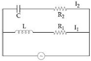
In the circuit shown,$C = \frac{\sqrt{3}}{2} \times 10^{-3} \, F$,$R_2 = 20 \, \Omega$,$L = \frac{\sqrt{3}}{10} \, H$,and $R_1 = 10 \, \Omega$. The current in the $L-R_1$ branch is $I_1$ and in the $C-R_2$ branch is $I_2$. The voltage of the $A.C.$ source is given by $V = 200\sqrt{2} \sin(100t) \, V$. The phase difference between $I_1$ and $I_2$ is:
A
$60^\circ$
B
$30^\circ$
C
$90^\circ$
D
None of these
Solution
(C) Given: $\omega = 100 \, rad/s$,$L = \frac{\sqrt{3}}{10} \, H$,$R_1 = 10 \, \Omega$,$C = \frac{\sqrt{3}}{2} \times 10^{-3} \, F$,$R_2 = 20 \, \Omega$.
For the $L-R_1$ branch:
Inductive reactance $X_L = \omega L = 100 \times \frac{\sqrt{3}}{10} = 10\sqrt{3} \, \Omega$.
The phase angle $\phi_1$ of current $I_1$ with respect to voltage $V$ is given by $\tan \phi_1 = -\frac{X_L}{R_1} = -\frac{10\sqrt{3}}{10} = -\sqrt{3}$.
Thus,$\phi_1 = -60^\circ$.
For the $C-R_2$ branch:
Capacitive reactance $X_C = \frac{1}{\omega C} = \frac{1}{100 \times \frac{\sqrt{3}}{2} \times 10^{-3}} = \frac{1}{\frac{\sqrt{3}}{20}} = \frac{20}{\sqrt{3}} \, \Omega$.
The phase angle $\phi_2$ of current $I_2$ with respect to voltage $V$ is given by $\tan \phi_2 = \frac{X_C}{R_2} = \frac{20/\sqrt{3}}{20} = \frac{1}{\sqrt{3}}$.
Thus,$\phi_2 = 30^\circ$.
The phase difference between $I_1$ and $I_2$ is $|\phi_2 - \phi_1| = |30^\circ - (-60^\circ)| = 90^\circ$.
0 likes
View Solution47
DifficultMCQ
In the circuit shown in the figure,what will be the reading of the voltmeter (in $, V$)?
A
$300$
B
$900$
C
$200$
D
$400$
Solution
(C) In an $LCR$ series circuit,the total voltage $V$ is given by the relation:
$V = \sqrt{V_{R}^{2} + (V_{L} - V_{C})^{2}}$
Given from the figure:
$V_{L} = 100 \, V$
$V_{C} = 100 \, V$
$V = 200 \, V$
Substituting these values into the formula:
$200 = \sqrt{V_{R}^{2} + (100 - 100)^{2}}$
$200 = \sqrt{V_{R}^{2} + 0^{2}}$
$200 = V_{R}$
Therefore,the reading of the voltmeter connected across the resistor $R$ is $200 \, V$.
0 likes
View Solution48
DifficultMCQ
The figure shows an $LCR$ series $AC$ circuit. If $L$ is removed from the circuit,the current leads the voltage by $45^o$,while if $C$ is removed,the current lags the voltage by $45^o$. The current passing in the original circuit is......$A$.
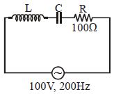
A
$2$
B
$1.5$
C
$1$
D
$0.5$
Solution
(C) In an $LCR$ series circuit,the phase angle $\phi$ is given by $\tan \phi = \frac{X_L - X_C}{R}$.
When $L$ is removed,the circuit becomes an $RC$ circuit. The current leads the voltage by $45^o$,so $\phi = -45^o$. Thus,$\tan(-45^o) = -\frac{X_C}{R}$,which implies $\frac{X_C}{R} = 1$,or $X_C = R$.
When $C$ is removed,the circuit becomes an $RL$ circuit. The current lags the voltage by $45^o$,so $\phi = 45^o$. Thus,$\tan(45^o) = \frac{X_L}{R}$,which implies $\frac{X_L}{R} = 1$,or $X_L = R$.
Since $X_L = R$ and $X_C = R$,it follows that $X_L = X_C$. This means the circuit is at resonance.
At resonance,the impedance of the circuit is $Z = R = 100 \, \Omega$.
The current in the original circuit is $I = \frac{V}{Z} = \frac{100 \, V}{100 \, \Omega} = 1 \, A$.
0 likes
View Solution49
DifficultMCQ
What will be the impedance of the circuit shown below in $\Omega$?
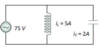
A
$5$
B
$10$
C
$25$
D
$75$
Solution
(C) The circuit consists of an inductor and a capacitor connected in parallel to an $AC$ voltage source of $V = 75 \, V$.
The current through the inductor is $i_L = 5 \, A$ and the current through the capacitor is $i_C = 2 \, A$.
In a parallel $LC$ circuit,the currents $i_L$ and $i_C$ are $180^{\circ}$ out of phase. Therefore,the net current $i_{LC}$ drawn from the source is the difference between the magnitudes of the two currents:
$i_{LC} = |i_L - i_C| = |5 \, A - 2 \, A| = 3 \, A$.
The equivalent impedance $Z$ of the parallel combination is given by Ohm's law:
$Z = \frac{V}{i_{LC}} = \frac{75 \, V}{3 \, A} = 25 \, \Omega$.
Thus,the impedance of the circuit is $25 \, \Omega$.
0 likes
View Solution50
MediumMCQ
As given in the figure,a series circuit connected across a $200\, V$,$60\, Hz$ line consists of a capacitor of capacitive reactance $30\,\Omega$,a non-inductive resistor of $44\,\Omega$,and a coil of inductive reactance $90\,\Omega$ and resistance $36\,\Omega$. The power dissipated in the coil is......$W$
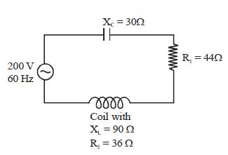
A
$320$
B
$176$
C
$144$
D
$0$
Solution
(C) The total resistance of the circuit is $R = R_1 + R_2 = 44\,\Omega + 36\,\Omega = 80\,\Omega$.
The total reactance of the circuit is $X = X_L - X_C = 90\,\Omega - 30\,\Omega = 60\,\Omega$.
The impedance of the circuit is $Z = \sqrt{R^2 + X^2} = \sqrt{80^2 + 60^2} = \sqrt{6400 + 3600} = \sqrt{10000} = 100\,\Omega$.
The $RMS$ current in the circuit is $I_{rms} = \frac{V_{rms}}{Z} = \frac{200\,V}{100\,\Omega} = 2\,A$.
The power dissipated in the coil is given by $P = I_{rms}^2 \times R_2$,where $R_2$ is the resistance of the coil.
$P = (2\,A)^2 \times 36\,\Omega = 4 \times 36 = 144\,W$.
0 likes
View SolutionAlternating Current — Inductance, Capacitance and Resistance in Series and Parallel · Frequently Asked Questions
1Are these Alternating Current questions useful for JEE and NEET?
Yes. All questions in this section are mapped to JEE Main and NEET exam patterns. Previous year questions from JEE Main, NEET, GUJCET and state-level exams are included with full solutions.
2Can I switch to Hindi or Gujarati for these questions?
Yes. Use the language tabs in the hero section or the sidebar to view the same questions and solutions in English, Hindi or Gujarati.
3How do I generate a question paper from this subtopic?
Use the Vedclass Exam Paper Generator — select the chapter and subtopic, set difficulty, and generate Sets A, B, C, D automatically. First 3 chapters of every subject are free.
Vedclass Products
For Students
Vedclass Test Series
Mock tests in real JEE/NEET style with performance analysis. 5-day free trial.
Start Free TrialFor Teachers
Exam Paper Generator
Generate Set A/B/C/D papers from this chapter in 2 minutes. 3 chapters free.
Try FreeFor Institutes
Online Exam Module
Live online exams with unlimited students, 360° analytics & white-label branding.
See DemoFor Teachers & Institutes
Generate a Alternating Current Exam Paper in 2 Minutes
Select subtopic & difficulty — Sets A, B, C, D auto-generated with No Repeat logic.
First 3 chapters of every subject are free — no payment required.