
A English
Mix Examples-Alternating Current Questions in English
Class 12 Physics · Alternating Current · Mix Examples-Alternating Current
92+
Questions
English
Language
100%
With Solutions
Showing 48 of 92 questions in English
1
MediumMCQ
If $L, C$ and $R$ represent inductance,capacitance and resistance respectively,then which of the following does not represent the dimensions of frequency?
A
$\frac{1}{RC}$
B
$\frac{R}{L}$
C
$\frac{1}{\sqrt{LC}}$
D
$\frac{C}{L}$
Solution
(D) The dimensions of the given quantities are:
$L = [M L^2 T^{-2} A^{-2}]$
$C = [M^{-1} L^{-2} T^4 A^2]$
$R = [M L^2 T^{-3} A^{-2}]$
$1$. For $\frac{1}{RC}$: The time constant $\tau = RC$ has dimensions of time $[T]$. Thus,$\frac{1}{RC}$ has dimensions of $[T^{-1}]$,which is frequency.
$2$. For $\frac{R}{L}$: The ratio $\frac{R}{L}$ has dimensions $[M L^2 T^{-3} A^{-2}] / [M L^2 T^{-2} A^{-2}] = [T^{-1}]$,which is frequency.
$3$. For $\frac{1}{\sqrt{LC}}$: The resonant frequency $\omega = \frac{1}{\sqrt{LC}}$ has dimensions $[T^{-1}]$,which is frequency.
$4$. For $\frac{C}{L}$: The dimensions are $[M^{-1} L^{-2} T^4 A^2] / [M L^2 T^{-2} A^{-2}] = [M^{-2} L^{-4} T^6 A^4]$. This does not represent frequency.
Therefore,the correct option is $D$.
0 likes
View Solution2
EasyMCQ
The power is transmitted from a power house on high voltage $ac$ because
A
Electric current travels faster at higher volts
B
It is more economical due to less power wastage
C
It is difficult to generate power at low voltage
D
Chances of stealing transmission lines are minimized
Solution
(B) The power transmitted is given by $P = VI$,where $V$ is the voltage and $I$ is the current. For a fixed power $P$,if the voltage $V$ is increased,the current $I$ decreases.
The power loss in the transmission lines due to heating is given by $P_{loss} = I^2 R$,where $R$ is the resistance of the wires.
Substituting $I = P/V$,we get $P_{loss} = (P/V)^2 R = P^2 R / V^2$.
Thus,$P_{loss} \propto 1/V^2$. By increasing the voltage $V$,the power loss is significantly reduced,making the transmission more economical and efficient. Therefore,option $B$ is correct.
0 likes
View Solution3
EasyMCQ
$A$ bulb is connected first with $DC$ and then $AC$ of the same voltage. In which case will it shine more brightly?
A
$AC$
B
$DC$
C
Brightness will be in the ratio $1:1.4$
D
Equally with both
Solution
(D) The power consumed by a bulb is given by the formula $P = \frac{V^2}{R}$,where $V$ is the voltage and $R$ is the resistance of the bulb.
For a bulb,the resistance $R$ is a constant property of the filament.
When connected to a $DC$ source of voltage $V$,the power consumed is $P_{DC} = \frac{V^2}{R}$.
When connected to an $AC$ source of the same $RMS$ voltage $V$,the power consumed is $P_{AC} = \frac{V_{rms}^2}{R} = \frac{V^2}{R}$.
Since the power consumed in both cases is identical,the brightness of the bulb will be the same.
0 likes
View Solution4
EasyMCQ
The phase angle between $e.m.f.$ and current in an $LCR$ series $ac$ circuit is:
A
$0$ to $\pi/2$
B
$\pi/4$
C
$\pi/2$
D
$\pi$
Solution
(A) In an $LCR$ series $ac$ circuit,the phase difference $\phi$ between the applied voltage $V$ and the current $i$ is given by $\tan \phi = \frac{X_L - X_C}{R}$.
If $X_L > X_C$,the circuit is inductive,and the phase angle $\phi$ lies between $0$ and $\pi/2$ (current lags behind voltage).
If $X_L < X_C$,the circuit is capacitive,and the phase angle $\phi$ lies between $-\pi/2$ and $0$ (current leads the voltage).
If $X_L = X_C$,the circuit is at resonance,and $\phi = 0$.
Therefore,the magnitude of the phase angle $|\phi|$ ranges from $0$ to $\pi/2$ depending on the values of $X_L$ and $X_C$.
0 likes
View Solution5
EasyMCQ
$A$ choke coil is preferred to a $Rheostat$ in $AC$ circuits because:
A
It consumes almost zero power
B
It increases current
C
It increases power
D
It increases voltage
Solution
A choke coil consists of an inductor with high inductance and negligible resistance. In an $AC$ circuit, the average power consumed is given by $P = V_{rms} I_{rms} \cos \phi$. For a pure inductor, the phase angle $\phi = 90^{\circ}$, so the power factor $\cos 90^{\circ} = 0$. Consequently, the power consumed by an ideal choke coil is zero. In contrast, a $Rheostat$ is a resistor that dissipates energy as heat ($I^2R$ loss). Therefore, a choke coil is preferred to control current in $AC$ circuits without significant power loss.
0 likes
View Solution6
EasyMCQ
$L$,$C$,and $R$ denote inductance,capacitance,and resistance respectively. Pick out the combination which does not have the dimensions of frequency.
A
$\frac{1}{RC}$
B
$\frac{R}{L}$
C
$\frac{1}{\sqrt{LC}}$
D
$\frac{C}{L}$
Solution
(D) The dimensions of the given quantities are as follows:
$1$. For an $RC$ circuit,the time constant is $\tau = RC$. Thus,the dimension of $\frac{1}{RC}$ is $[T^{-1}]$,which is the dimension of frequency.
$2$. For an $RL$ circuit,the time constant is $\tau = \frac{L}{R}$. Thus,the dimension of $\frac{R}{L}$ is $[T^{-1}]$,which is the dimension of frequency.
$3$. For an $LC$ circuit,the resonant frequency is given by $\omega = \frac{1}{\sqrt{LC}}$. Thus,the dimension of $\frac{1}{\sqrt{LC}}$ is $[T^{-1}]$,which is the dimension of frequency.
$4$. For the combination $\frac{C}{L}$,we know that the resonant frequency $\omega = \frac{1}{\sqrt{LC}}$. Therefore,$\omega^2 = \frac{1}{LC}$,which implies $LC = \frac{1}{\omega^2}$. The dimension of $LC$ is $[T^2]$. Thus,the dimension of $\frac{C}{L}$ is $\frac{[C]}{[L]} = \frac{[C]^2}{[LC]} = \frac{[C]^2}{[T^2]}$. This does not have the dimensions of frequency.
Therefore,the correct option is $D$.
0 likes
View Solution7
EasyMCQ
In an $A.C.$ circuit,the current:
A
Always leads the voltage
B
Always lags behind the voltage
C
Is always in phase with the voltage
D
May lead or lag behind or be in phase with the voltage
Solution
(D) In an $A.C.$ circuit,the phase relationship between current and voltage depends on the components present in the circuit.
If the circuit is purely resistive,the current is in phase with the voltage.
If the circuit is inductive,the current lags behind the voltage.
If the circuit is capacitive,the current leads the voltage.
Therefore,the current may lead,lag,or be in phase with the voltage depending on the circuit configuration.
0 likes
View Solution8
DifficultMCQ
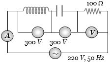
In the circuit shown below,what will be the readings of the voltmeter and ammeter?
A
$800 \, V, 2 \, A$
B
$300 \, V, 2 \, A$
C
$220 \, V, 2.2 \, A$
D
$100 \, V, 2 \, A$
Solution
(C) From the circuit diagram,we have an $LCR$ series circuit connected to an $AC$ source of $220 \, V$.
The voltmeter is connected across the resistor,so its reading is the voltage across the resistor $(V_R)$.
In an $LCR$ series circuit,the total voltage $V$ is given by $V = \sqrt{V_R^2 + (V_L - V_C)^2}$.
From the diagram,the voltage across the inductor $V_L = 300 \, V$ and the voltage across the capacitor $V_C = 300 \, V$.
Substituting these values: $220 = \sqrt{V_R^2 + (300 - 300)^2}$.
$220 = \sqrt{V_R^2 + 0} = V_R$.
Thus,the voltmeter reading is $V_R = 220 \, V$.
The current $i$ in the circuit is given by $i = \frac{V_R}{R}$.
Given $R = 100 \, \Omega$,we have $i = \frac{220}{100} = 2.2 \, A$.
Therefore,the voltmeter reading is $220 \, V$ and the ammeter reading is $2.2 \, A$.
0 likes
View Solution9
DifficultMCQ
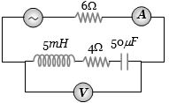
In the circuit shown in the figure,the $ac$ source gives a voltage $V = 20\cos(2000t)$. Neglecting source resistance,the voltmeter and ammeter readings will be:
A
$0\,V, 0.47\,A$
B
$1.68\,V, 0.47\,A$
C
$0\,V, 1.4\,A$
D
$5.6\,V, 1.4\,A$
Solution
(D) The circuit consists of a resistor $R_1 = 6\,\Omega$ in series with an $LCR$ branch containing $L = 5\,mH$,$R_2 = 4\,\Omega$,and $C = 50\,\mu F$.
Given $\omega = 2000\,rad/s$.
Inductive reactance $X_L = \omega L = 2000 \times 5 \times 10^{-3} = 10\,\Omega$.
Capacitive reactance $X_C = \frac{1}{\omega C} = \frac{1}{2000 \times 50 \times 10^{-6}} = 10\,\Omega$.
Total resistance $R_{total} = R_1 + R_2 = 6 + 4 = 10\,\Omega$.
Since $X_L = X_C$,the circuit is in resonance.
Total impedance $Z = \sqrt{R_{total}^2 + (X_L - X_C)^2} = \sqrt{10^2 + 0^2} = 10\,\Omega$.
Peak current $I_0 = \frac{V_0}{Z} = \frac{20}{10} = 2\,A$.
$RMS$ current $I_{rms} = \frac{I_0}{\sqrt{2}} = \frac{2}{1.414} \approx 1.41\,A$.
The voltmeter is connected across the $LCR$ branch. The impedance of this branch is $Z_{LCR} = \sqrt{R_2^2 + (X_L - X_C)^2} = \sqrt{4^2 + 0^2} = 4\,\Omega$.
The voltage across this branch is $V_{LCR} = I_{rms} \times Z_{LCR} = 1.41 \times 4 = 5.64\,V \approx 5.6\,V$.
0 likes
View Solution10
MediumMCQ
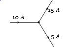
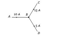
Is the current distribution shown in the figure possible?
A
Yes
B
No
C
Cannot be predicted
D
Insufficient data to reply
Solution
(A) Yes, it is possible in an $AC$ circuit. Kirchhoff's Current Law $(KCL)$ states that the algebraic sum of currents at a junction is zero for $DC$ circuits. However, in $AC$ circuits, the currents are phasors. The sum of the currents at the junction $B$ is given by the vector sum of the phasors: $\vec{I}_{in} = \vec{I}_{out1} + \vec{I}_{out2}$. If the phase angles between the currents are such that the vector sum of $15 \ A$ and $5 \ A$ results in $10 \ A$, then this distribution is possible.
0 likes
View Solution11
MediumMCQ
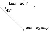
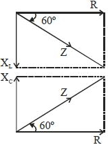
The vector diagram of current and voltage for a circuit is as shown. The components of the circuit will be
A
$LCR$
B
$LR$
C
$LCR$ or $LR$
D
None of these
Solution
(C) From the given phasor diagram,it is observed that the current $i_{rms}$ is lagging behind the voltage $E_{rms}$ by a phase angle of $\phi = 45^\circ$.
In an $AC$ circuit,current lags behind voltage when the circuit is inductive in nature.
An $LR$ circuit is inherently inductive,so the current will always lag behind the voltage.
An $LCR$ circuit can also be inductive if the inductive reactance $X_L$ is greater than the capacitive reactance $X_C$ (i.e.,$X_L > X_C$).
Therefore,the circuit could be either an $LR$ circuit or an $LCR$ circuit with $X_L > X_C$.
Thus,the correct option is $C$.
0 likes
View Solution12
MediumMCQ
The $i -
u$ curve for an anti-resonant circuit is:
u$ curve for an anti-resonant circuit is:
A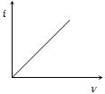
$A$
B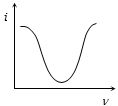
$B$
C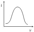
$C$
D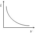
$D$
Solution
(B) In an anti-resonant circuit (parallel $LC$ circuit),the impedance is maximum at the resonant frequency $\nu_0$.
Since the current $i = \frac{V}{Z}$,the current $i$ is minimum at the resonant frequency.
At frequencies other than the resonant frequency,the impedance $Z$ decreases,causing the current $i$ to increase.
Therefore,the $i -
u$ curve shows a minimum at the resonant frequency,which corresponds to the graph shown in option $B$.
0 likes
View Solution13
MediumMCQ
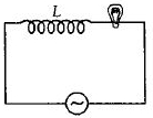
$A$ coil of self-inductance $L$ is connected in series with a bulb $B$ and an $AC$ source. The brightness of the bulb decreases when:
A
the number of turns in the coil is reduced.
B
a capacitance of reactance $X_C = X_L$ is included in the same circuit.
C
an iron rod is inserted into the coil.
D
the frequency of the $AC$ source is decreased.
Solution
(C) The circuit consists of an inductor $L$ and a bulb $B$ in series with an $AC$ source. The impedance of the circuit is $Z = \sqrt{R^2 + X_L^2}$,where $R$ is the resistance of the bulb and $X_L = \omega L$ is the inductive reactance.
When an iron rod is inserted into the coil,the permeability of the core increases,which significantly increases the self-inductance $L$ of the coil.
Since $X_L = \omega L$,an increase in $L$ leads to an increase in the inductive reactance $X_L$.
As the total impedance $Z = \sqrt{R^2 + X_L^2}$ increases,the total current in the circuit $I = \frac{V}{Z}$ decreases.
The brightness of the bulb depends on the power dissipated,$P = I^2 R$. Since the current $I$ decreases,the power dissipated by the bulb decreases,and thus the brightness of the bulb decreases.
0 likes
View Solution14
MediumMCQ
$A$ $100 \, \Omega$ resistance and a capacitor of $100 \, \Omega$ reactance are connected in series across a $220 \, V$ source. When the capacitor is $50\%$ charged,the peak value of the displacement current is.....$A$
A
$4.4$
B
$11\sqrt{2}$
C
$2.2$
D
$11$
Solution
(C) Given: Resistance $R = 100 \, \Omega$,Capacitive reactance $X_C = 100 \, \Omega$,and $RMS$ voltage $V_{rms} = 220 \, V$.
The total impedance of the $RC$ series circuit is $Z = \sqrt{R^2 + X_C^2} = \sqrt{100^2 + 100^2} = 100\sqrt{2} \, \Omega$.
The peak voltage of the source is $V_0 = V_{rms} \sqrt{2} = 220\sqrt{2} \, V$.
The peak conduction current in the circuit is $I_0 = \frac{V_0}{Z} = \frac{220\sqrt{2}}{100\sqrt{2}} = 2.2 \, A$.
According to Maxwell's modification of Ampere's law,the displacement current $I_d$ between the plates of a capacitor is equal to the conduction current $I_c$ in the connecting wires.
Therefore,the peak value of the displacement current is equal to the peak value of the conduction current,which is $2.2 \, A$.
0 likes
View Solution15
DifficultMCQ
$A$ $\frac{2.5}{\pi} \mu F$ capacitor and $3000 \, \Omega$ resistor are joined in series to an $AC$ source of $200 \, V$ and $50 \, Hz$ frequency. The power factor of the circuit and the power dissipated in it will respectively be:
A
$0.6, 0.06 \, W$
B
$0.06, 0.6 \, W$
C
$0.6, 4.8 \, W$
D
$4.8, 0.6 \, W$
Solution
(C) Given: $C = \frac{2.5}{\pi} \times 10^{-6} \, F$,$R = 3000 \, \Omega$,$V_{rms} = 200 \, V$,$\nu = 50 \, Hz$.
First,calculate the capacitive reactance $X_C = \frac{1}{2\pi \nu C} = \frac{1}{2\pi \times 50 \times (\frac{2.5}{\pi} \times 10^{-6})} = \frac{1}{250 \times 10^{-6}} = 4000 \, \Omega$.
The impedance of the circuit is $Z = \sqrt{R^2 + X_C^2} = \sqrt{3000^2 + 4000^2} = 5000 \, \Omega$.
The power factor is $\cos \phi = \frac{R}{Z} = \frac{3000}{5000} = 0.6$.
The power dissipated is $P = \frac{V_{rms}^2 \cos \phi}{Z} = \frac{200^2 \times 0.6}{5000} = \frac{40000 \times 0.6}{5000} = 8 \times 0.6 = 4.8 \, W$.
0 likes
View Solution16
MediumMCQ
In an $LCR$ circuit $R = 100 \ \Omega$. When capacitance $C$ is removed,the current lags behind the voltage by $\pi /3$. When inductance $L$ is removed,the current leads the voltage by $\pi /3$. The impedance of the circuit is......$\Omega$.
A
$50$
B
$100$
C
$200$
D
$400$
Solution
(B) When $C$ is removed,the circuit becomes an $RL$ circuit. The phase angle $\phi$ is given by $\tan \phi = \frac{X_L}{R}$.
Given $\phi = \pi /3$,so $\tan(\pi /3) = \frac{X_L}{R} \implies \sqrt{3} = \frac{X_L}{R} \implies X_L = R\sqrt{3}$.
When $L$ is removed,the circuit becomes an $RC$ circuit. The phase angle $\phi$ is given by $\tan \phi = \frac{X_C}{R}$.
Given $\phi = \pi /3$,so $\tan(\pi /3) = \frac{X_C}{R} \implies \sqrt{3} = \frac{X_C}{R} \implies X_C = R\sqrt{3}$.
Since $X_L = X_C$,the circuit is in a state of resonance.
In an $LCR$ circuit at resonance,the impedance $Z = R$.
Given $R = 100 \ \Omega$,therefore $Z = 100 \ \Omega$.
0 likes
View Solution17
MediumMCQ
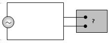
The following figure shows an $AC$ generator connected to a 'black box' through a pair of terminals. The box contains possible $R, L, C$ or their combination,whose elements and arrangements are not known to us. Measurements outside the box reveal that $e = 75 \sin(\omega t) \text{ V}$ and $i = 1.5 \sin(\omega t + 45^\circ) \text{ A}$. Then,the wrong statement is:
A
There must be a capacitor in the box.
B
There must be an inductor in the box.
C
There must be a resistance in the box.
D
The power factor is $0.707$.
Solution
(B) Given: $e = 75 \sin(\omega t) \text{ V}$ and $i = 1.5 \sin(\omega t + 45^\circ) \text{ A}$.
Here,the current $i$ leads the voltage $e$ by a phase angle of $\phi = 45^\circ$.
Since the current leads the voltage,the circuit must be capacitive in nature. This implies that there must be a capacitor in the box.
Since there is a phase difference between voltage and current,there must be a resistance $R$ in the box to provide the phase shift.
Because the circuit is capacitive,the net reactance $X = X_C - X_L$ must be capacitive $(X_C > X_L)$. This does not strictly rule out the presence of an inductor,but it implies the net effect is capacitive. However,the statement 'There must be an inductor' is not necessarily true,making it the wrong statement.
The power factor is $\cos \phi = \cos(45^\circ) = 1/\sqrt{2} \approx 0.707$. Thus,option $(d)$ is correct.
Therefore,the wrong statement is $(b)$.
0 likes
View Solution18
MediumMCQ
$L$,$C$,and $R$ represent the physical quantities inductance,capacitance,and resistance,respectively. Which of the following combinations has the dimensions of frequency?
A
$\frac{1}{RC}$ and $\frac{R}{L}$
B
$\frac{1}{\sqrt{RC}}$ and $\sqrt{\frac{R}{L}}$
C
$\sqrt{LC}$
D
$\frac{C}{L}$
Solution
(A) The dimension of frequency is $[T^{-1}]$.
$1$. For an $RC$ circuit,the time constant is $\tau = RC$. Since $\tau$ has the dimension of time $[T]$,the quantity $\frac{1}{RC}$ has the dimension of frequency $[T^{-1}]$.
$2$. For an $RL$ circuit,the time constant is $\tau = \frac{L}{R}$. Since $\tau$ has the dimension of time $[T]$,the quantity $\frac{R}{L}$ has the dimension of frequency $[T^{-1}]$.
$3$. For an $LC$ circuit,the resonant frequency is given by $\omega = \frac{1}{\sqrt{LC}}$. Thus,$\frac{1}{\sqrt{LC}}$ also has the dimension of frequency $[T^{-1}]$.
Comparing these with the given options,the combination $\frac{1}{RC}$ and $\frac{R}{L}$ represents dimensions of frequency.
0 likes
View Solution19
MediumMCQ
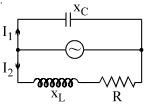
In the shown $AC$ circuit,the phase difference between currents $I_1$ and $I_2$ is:
A
$\frac{\pi}{2} - \tan^{-1} \left( \frac{X_L}{R} \right)$
B
$\tan^{-1} \left( \frac{X_L - X_C}{R} \right)$
C
$\frac{\pi}{2} + \tan^{-1} \left( \frac{X_L}{R} \right)$
D
$\tan^{-1} \left( \frac{X_L - X_C}{R} \right) + \frac{\pi}{2}$
Solution
(C) In the upper branch containing the capacitor,the current $I_1$ leads the applied voltage $V$ by a phase angle of $\phi_1 = \frac{\pi}{2}$.
In the lower branch containing the resistor $R$ and inductor $X_L$,the current $I_2$ lags behind the applied voltage $V$ by a phase angle $\phi_2 = \tan^{-1} \left( \frac{X_L}{R} \right)$.
The total phase difference between the two currents $I_1$ and $I_2$ is the sum of their individual phase shifts relative to the voltage $V$.
Therefore,the phase difference $\Delta \phi = \phi_1 + \phi_2 = \frac{\pi}{2} + \tan^{-1} \left( \frac{X_L}{R} \right)$.
0 likes
View Solution20
MediumMCQ
The reactance of a circuit is zero. It is possible that the circuit contains:
A
an inductor and a capacitor
B
an inductor but no capacitor
C
neither an inductor nor a capacitor
D
Both $(A)$ and $(C)$
Solution
(D) The reactance of a circuit is given by $X = X_L - X_C$,where $X_L = \omega L$ is the inductive reactance and $X_C = 1/(\omega C)$ is the capacitive reactance.
For the net reactance to be zero $(X = 0)$:
$1$. If the circuit contains both an inductor and a capacitor,they must be in resonance such that $X_L = X_C$,which results in $X = 0$.
$2$. If the circuit contains only resistors,there are no inductors or capacitors present,so $X_L = 0$ and $X_C = 0$,leading to $X = 0$.
Therefore,the circuit can contain both an inductor and a capacitor (in resonance) or neither an inductor nor a capacitor (purely resistive circuit).
Thus,the correct option is $(D)$.
0 likes
View Solution21
DifficultMCQ
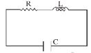
An $LCR$ circuit is equivalent to a damped oscillator. $A$ capacitor is charged to a charge $Q_0$ as shown and then connected to $L$ and $R$. If a student plots graphs of the square of the maximum charge on the capacitor $(Q^2_{max})$ versus time for two different values of inductors $L_1$ and $L_2$ $(L_1 > L_2)$, which of the following graphs will correctly represent it? (The diagram is schematic and not drawn to scale.)
A
B
C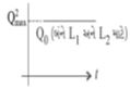
D
Solution
(A) In an $LCR$ circuit, the charge on the capacitor at any time $t$ is given by $Q(t) = Q_0 e^{-Rt/2L} \cos(\omega' t + \phi)$.
The maximum charge on the capacitor at any cycle is given by $Q_{max}(t) = Q_0 e^{-Rt/2L}$.
Squaring both sides, we get $Q^2_{max}(t) = Q^2_0 e^{-Rt/L}$.
This equation represents an exponential decay of the square of the maximum charge with time.
The rate of decay depends on the factor $R/L$. Since $L_1 > L_2$, the decay constant $R/L_1$ is smaller than $R/L_2$.
Therefore, the charge in the circuit with $L_2$ decays faster than the circuit with $L_1$.
Thus, the graph for $L_1$ will show a slower decay compared to the graph for $L_2$.
0 likes
View Solution22
DifficultMCQ
In a series $LCR$ circuit,$R = 200 \, \Omega$ and the voltage and frequency of the main supply are $220 \, V$ and $50 \, Hz$ respectively. On taking out the capacitance from the circuit,the current lags behind the voltage by $30^\circ$. On taking out the inductor from the circuit,the current leads the voltage by $30^\circ$. The power dissipated in the $LCR$ circuit is......$W$.
A
$242$
B
$305$
C
$210$
D
$0$
Solution
(A) When capacitance is removed,the circuit becomes an $LR$ circuit.
Given the phase angle $\phi = 30^\circ$,we have $\tan \phi = \frac{\omega L}{R}$.
$\omega L = R \tan 30^\circ = 200 \times \frac{1}{\sqrt{3}} = \frac{200}{\sqrt{3}} \, \Omega$.
When the inductor is removed,the circuit becomes a $CR$ circuit.
Given the phase angle $\phi = 30^\circ$,we have $\tan \phi = \frac{1}{\omega C R}$.
$\frac{1}{\omega C} = R \tan 30^\circ = 200 \times \frac{1}{\sqrt{3}} = \frac{200}{\sqrt{3}} \, \Omega$.
In the original $LCR$ circuit,the impedance $Z$ is given by $Z = \sqrt{R^2 + (\omega L - \frac{1}{\omega C})^2}$.
Substituting the values: $Z = \sqrt{200^2 + (\frac{200}{\sqrt{3}} - \frac{200}{\sqrt{3}})^2} = \sqrt{200^2 + 0} = 200 \, \Omega$.
The power dissipated in an $AC$ circuit is $P = V_{rms} I_{rms} \cos \phi$,where $\cos \phi = \frac{R}{Z}$.
Since $\omega L = \frac{1}{\omega C}$,the circuit is in resonance,so $\phi = 0^\circ$ and $\cos \phi = 1$.
$P = \frac{V_{rms}^2}{Z^2} \times R = \frac{220^2}{200^2} \times 200 = \frac{220 \times 220}{200} = 242 \, W$.
0 likes
View Solution23
DifficultMCQ
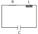
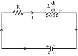
An $LCR$ circuit is equivalent to a damped pendulum. In an $LCR$ circuit,the capacitor is charged to $Q_0$ and then connected to the $L$ and $R$ as shown below. If a student plots graphs of the square of maximum charge $(Q_{Max}^2)$ on the capacitor with time $(t)$ for two different values $L_1$ and $L_2$ $(L_1 > L_2)$ of $L$,then which of the following represents this graph correctly? (Plots are schematic and not drawn to scale.)
A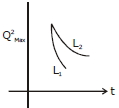
B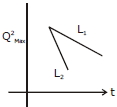
C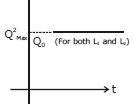
D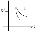
Solution
(A) Applying Kirchhoff's Voltage Law $(KVL)$ to the $LCR$ circuit at any time $t$:
$\frac{q}{C} - iR - L \frac{di}{dt} = 0$
Since $i = -\frac{dq}{dt}$,we have:
$\frac{q}{C} + R \frac{dq}{dt} + L \frac{d^2q}{dt^2} = 0$
Rearranging gives the differential equation for a damped harmonic oscillator:
$\frac{d^2q}{dt^2} + \frac{R}{L} \frac{dq}{dt} + \frac{q}{LC} = 0$
The charge on the capacitor decays as $q(t) = Q_0 e^{-\frac{Rt}{2L}} \cos(\omega' t + \phi)$.
The maximum charge at any cycle is given by the envelope $Q_{Max} = Q_0 e^{-\frac{Rt}{2L}}$.
Squaring this,we get $Q_{Max}^2 = Q_0^2 e^{-\frac{Rt}{L}}$.
Comparing the decay constant $\lambda = \frac{R}{L}$,we see that for a fixed $R$,a smaller $L$ results in a larger decay constant,meaning the charge decays faster.
Since $L_1 > L_2$,the decay constant for $L_2$ is larger than for $L_1$.
Therefore,the curve for $L_2$ decays faster than the curve for $L_1$.
0 likes
View Solution24
MediumMCQ
In an $A.C.$ circuit,the instantaneous $e.m.f.$ and current are given by:
$e = 100 \sin(20t)$
$i = 20 \sin(30t - \frac{\pi}{4})$
In one cycle of $A.C.$,the average power consumed by the circuit and the wattless current are,respectively:
$e = 100 \sin(20t)$
$i = 20 \sin(30t - \frac{\pi}{4})$
In one cycle of $A.C.$,the average power consumed by the circuit and the wattless current are,respectively:
A
$\frac{1000}{\sqrt{2}}, 10$
B
$\frac{50}{\sqrt{2}}, 0$
C
$50, 0$
D
$50, 10$
Solution
(A) The given equations are $e = 100 \sin(20t)$ and $i = 20 \sin(30t - \frac{\pi}{4})$.
Note: The frequencies of the $e.m.f.$ and current are different $(20 \neq 30)$. In such a case,the average power over a complete cycle is zero because the phase difference $\phi$ is not constant.
However,if we assume the question implies a standard phase difference $\phi = 45^{\circ}$ (or $\frac{\pi}{4}$) for a single frequency circuit,the calculation is as follows:
Average power $P_{\text{avg}} = V_{\text{rms}} I_{\text{rms}} \cos \phi = \left(\frac{V_0}{\sqrt{2}}\right) \left(\frac{I_0}{\sqrt{2}}\right) \cos \phi$
$P_{\text{avg}} = \left(\frac{100}{\sqrt{2}}\right) \left(\frac{20}{\sqrt{2}}\right) \cos 45^{\circ} = \frac{2000}{2} \times \frac{1}{\sqrt{2}} = \frac{1000}{\sqrt{2}} \text{ W}$.
Wattless current $I_w = I_{\text{rms}} \sin \phi = \left(\frac{I_0}{\sqrt{2}}\right) \sin 45^{\circ} = \left(\frac{20}{\sqrt{2}}\right) \times \frac{1}{\sqrt{2}} = \frac{20}{2} = 10 \text{ A}$.
Thus,the values are $\frac{1000}{\sqrt{2}}$ and $10$.
0 likes
View Solution25
MediumMCQ
An $LCR$ series circuit with $100 \,\Omega$ resistance is connected to an $AC$ source of $200 \,V$ and angular frequency $300 \,rad/s$. When only the capacitance is removed,the current leads the voltage by $60^o$. When only the inductance is removed,the current lags the voltage by $60^o$. Then the current and power dissipated in the $LCR$ circuit are respectively:
A
$1 \,A, 200 \,W$
B
$1 \,A, 400 \,W$
C
$2 \,A, 200 \,W$
D
$2 \,A, 400 \,W$
Solution
(D) Given: $R = 100 \,\Omega$,$V = 200 \,V$,$\omega = 300 \,rad/s$.
When capacitance is removed,the circuit becomes an $LR$ circuit. The phase angle $\phi_1 = 60^o$ (current lags voltage). Wait,the problem states current leads by $60^o$ when capacitance is removed,which implies an $RC$ circuit. Let's re-evaluate: If $C$ is removed,we have $LR$ circuit,$\tan(60^o) = \frac{X_L}{R} \implies X_L = R \tan(60^o) = 100\sqrt{3} \,\Omega$.
If $L$ is removed,we have $RC$ circuit,$\tan(60^o) = \frac{X_C}{R} \implies X_C = R \tan(60^o) = 100\sqrt{3} \,\Omega$.
Since $X_L = X_C$,the circuit is at resonance when all components are connected.
At resonance,$Z = R = 100 \,\Omega$.
Current $I = \frac{V}{Z} = \frac{200}{100} = 2 \,A$.
Power dissipated $P = I^2 R = (2)^2 \times 100 = 400 \,W$.
0 likes
View Solution26
EasyMCQ
Statement-$I$: $A$ capacitor can be used in an $a.c.$ circuit in place of a choke coil.
Statement-$II$: $A$ capacitor blocks $d.c.$ and allows $a.c.$ to pass.
Statement-$II$: $A$ capacitor blocks $d.c.$ and allows $a.c.$ to pass.
A
Statement-$I$ is true, Statement-$II$ is true; Statement-$II$ is not the correct explanation of Statement-$I$.
B
Statement-$I$ is false, Statement-$II$ is true.
C
Statement-$I$ is true, Statement-$II$ is false.
D
Statement-$I$ is true, Statement-$II$ is true; Statement-$II$ is the correct explanation of Statement-$I$.
Solution
(D) Statement-$I$ is true because a capacitor can be used to limit current in an $a.c.$ circuit without dissipating power, similar to a choke coil.
Statement-$II$ is true because the capacitive reactance $X_C = 1 / (2\pi f C)$. For $d.c.$, $f = 0$, so $X_C = \infty$ (blocking $d.c.$), while for $a.c.$, it offers finite reactance.
Since a capacitor provides reactance to limit current in $a.c.$ circuits without power loss, Statement-$II$ correctly explains why it can replace a choke coil.
0 likes
View Solution27
DifficultMCQ
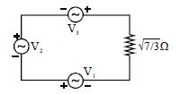
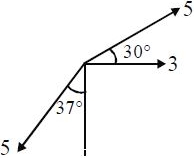
Three alternating voltage sources $V_1 = 3 \sin \omega t \text{ V}$,$V_2 = 5 \sin(\omega t + \phi_1) \text{ V}$,and $V_3 = 5 \sin(\omega t - \phi_2) \text{ V}$ are connected in series with a resistor $R = \sqrt{\frac{7}{3}} \, \Omega$ as shown in the figure (where $\phi_1 = 30^\circ$ and $\phi_2 = 127^\circ$). Find the peak current (in Ampere) through the resistor.
A
$3$
B
$4$
C
$5$
D
$6$
Solution
(A) The net voltage $V_{net}$ across the resistor is the sum of the three sources: $V_{net} = V_1 + V_2 + V_3$.
Representing these as phasors:
$V_1 = 3 \angle 0^\circ = 3 + j0$
$V_2 = 5 \angle 30^\circ = 5(\cos 30^\circ + j \sin 30^\circ) = 5(\frac{\sqrt{3}}{2} + j \frac{1}{2}) = \frac{5\sqrt{3}}{2} + j 2.5$
$V_3 = 5 \angle -127^\circ = 5(\cos(-127^\circ) + j \sin(-127^\circ)) \approx 5(-0.6 - j 0.8) = -3 - j 4$
Summing the components:
$V_{real} = 3 + \frac{5\sqrt{3}}{2} - 3 = \frac{5\sqrt{3}}{2} \approx 4.33$
$V_{imag} = 0 + 2.5 - 4 = -1.5$
Peak voltage $V_{max} = \sqrt{V_{real}^2 + V_{imag}^2} = \sqrt{(\frac{5\sqrt{3}}{2})^2 + (-1.5)^2} = \sqrt{\frac{75}{4} + 2.25} = \sqrt{18.75 + 2.25} = \sqrt{21} \text{ V}$.
Peak current $I_{max} = \frac{V_{max}}{R} = \frac{\sqrt{21}}{\sqrt{7/3}} = \sqrt{\frac{21 \times 3}{7}} = \sqrt{9} = 3 \text{ A}$.
0 likes
View Solution28
AdvancedMCQ
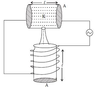
The figure shows a system of an inductor and a parallel plate capacitor made of $2$ parallel circular plates of area $A$,filled with a dielectric liquid of dielectric constant $K$. $A$ small leak develops in the capacitor,and the liquid starts to fill the inductor of the same dimensions having $n$ turns per unit length. Find the ratio of the magnitude of the initial reactance to the final reactance of the circuit after the liquid fills the inductor completely.
Given: $\omega^2 A^2 n^2 = c^2$
$\omega \rightarrow$ angular frequency of $AC$
$c \rightarrow$ speed of light
$\mu_r \rightarrow$ relative permeability of the liquid
Given: $\omega^2 A^2 n^2 = c^2$
$\omega \rightarrow$ angular frequency of $AC$
$c \rightarrow$ speed of light
$\mu_r \rightarrow$ relative permeability of the liquid
A
$K\frac{(K - 1)}{(\mu_r + 1)}$
B
$\frac{(1 - K)}{K(1 - \mu_r)}$
C
$\frac{(1 + \mu_r)K}{(1 + K)}$
D
$\frac{(K + 1)}{K(1 - \mu_r)}$
Solution
(B) The initial reactance of the circuit is $X_i = |X_{Ci} - X_{Li}| = |\frac{1}{\omega C_i} - \omega L_i|$.
Initially,the capacitor is filled with liquid $(C_i = \frac{K \varepsilon_0 A}{\ell})$ and the inductor is empty $(L_i = \mu_0 n^2 A \ell)$.
So,$X_i = |\frac{\ell}{\omega K \varepsilon_0 A} - \omega \mu_0 n^2 A \ell|$.
After the liquid fills the inductor,the capacitor becomes empty $(C_f = \frac{\varepsilon_0 A}{\ell})$ and the inductor is filled with liquid $(L_f = \mu_0 \mu_r n^2 A \ell)$.
So,$X_f = |\frac{\ell}{\omega \varepsilon_0 A} - \omega \mu_0 \mu_r n^2 A \ell|$.
Taking the ratio $\frac{X_i}{X_f} = \left| \frac{\frac{\ell}{\omega K \varepsilon_0 A} - \omega \mu_0 n^2 A \ell}{\frac{\ell}{\omega \varepsilon_0 A} - \omega \mu_0 \mu_r n^2 A \ell} \right|$.
Multiplying numerator and denominator by $\omega \varepsilon_0 A / \ell$,we get $\frac{X_i}{X_f} = \left| \frac{\frac{1}{K} - \omega^2 \mu_0 \varepsilon_0 n^2 A^2}{1 - \omega^2 \mu_0 \varepsilon_0 \mu_r n^2 A^2} \right|$.
Using $\mu_0 \varepsilon_0 = \frac{1}{c^2}$ and $\omega^2 A^2 n^2 = c^2$,the term $\omega^2 \mu_0 \varepsilon_0 n^2 A^2 = \frac{c^2}{c^2} = 1$.
Thus,$\frac{X_i}{X_f} = \left| \frac{\frac{1}{K} - 1}{1 - \mu_r} \right| = \left| \frac{1 - K}{K(1 - \mu_r)} \right| = \frac{1 - K}{K(1 - \mu_r)}$ (assuming $K > 1$ and $\mu_r > 1$ or vice versa to maintain magnitude).
0 likes
View Solution29
DifficultMCQ
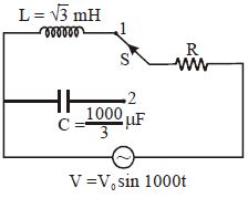
In the given $AC$ circuit,when switch $S$ is at position $1$,the source $emf$ leads the current by $\pi / 6$. Now,if the switch is at position $2$,then
A
current leads source $emf$ by $\frac{\pi}{4}$
B
current leads source $emf$ by $\frac{\pi}{3}$
C
source $emf$ leads current by $\frac{\pi}{4}$
D
source $emf$ leads current by $\frac{\pi}{3}$
Solution
(A) In position $1$,the circuit is an $LR$ series circuit. The phase angle $\phi$ is given by $\tan \phi = \frac{X_L}{R} = \frac{\omega L}{R}$.
Given $\phi = \pi / 6$,$\omega = 1000 \text{ rad/s}$,and $L = \sqrt{3} \text{ mH} = \sqrt{3} \times 10^{-3} \text{ H}$.
$\tan(\pi / 6) = \frac{1000 \times \sqrt{3} \times 10^{-3}}{R} \implies \frac{1}{\sqrt{3}} = \frac{\sqrt{3}}{R} \implies R = 3 \, \Omega$.
In position $2$,the circuit is an $RC$ series circuit. The phase angle $\phi$ is given by $\tan \phi = \frac{X_C}{R} = \frac{1}{\omega C R}$.
Given $C = \frac{1000}{3} \, \mu\text{F} = \frac{1000}{3} \times 10^{-6} \text{ F}$.
$\tan \phi = \frac{1}{1000 \times (\frac{1000}{3} \times 10^{-6}) \times 3} = \frac{1}{1000 \times \frac{1}{3} \times 10^{-3} \times 3} = \frac{1}{1} = 1$.
Since $\tan \phi = 1$,$\phi = \pi / 4$. In an $RC$ circuit,current leads the source $emf$ by $\phi$. Therefore,current leads source $emf$ by $\pi / 4$.
0 likes
View Solution30
MediumMCQ
$A$ steady current of magnitude $I$ and an $AC$ current of peak value $I$ are allowed to pass through identical resistors for the same time. The ratio of heat produced in the two resistors will be
A
$2 : 1$
B
$1 : 2$
C
$1 : 1$
D
None of these
Solution
(A) The heat produced by a steady $DC$ current $I$ in a resistor $R$ over time $t$ is given by $H_{DC} = I^2 R t$.
The heat produced by an $AC$ current with peak value $I$ in the same resistor $R$ over the same time $t$ is given by $H_{AC} = I_{rms}^2 R t$.
Since $I_{rms} = \frac{I}{\sqrt{2}}$,we have $H_{AC} = \left(\frac{I}{\sqrt{2}}\right)^2 R t = \frac{I^2 R t}{2}$.
Therefore,the ratio of heat produced is $\frac{H_{DC}}{H_{AC}} = \frac{I^2 R t}{I^2 R t / 2} = \frac{2}{1}$.
0 likes
View Solution31
MediumMCQ
$A$ coil,a capacitor,and an $AC$ source of $rms$ voltage $24 \,V$ are connected in series. By varying the frequency of the source,a maximum $rms$ current of $6 \,A$ is observed. If the coil is connected to a battery of $emf$ $12 \,V$ and internal resistance $4 \,\Omega$,then the current through it in the steady state is......$A$
A
$2.4$
B
$1.8$
C
$1.5$
D
$1.2$
Solution
(C) In an $LCR$ series circuit,the maximum current occurs at resonance,where the impedance $Z$ is equal to the resistance $R$ of the coil.
Given $V_{rms} = 24 \,V$ and $I_{rms, max} = 6 \,A$.
At resonance,$Z = R = V_{rms} / I_{rms, max} = 24 / 6 = 4 \,\Omega$.
This $R = 4 \,\Omega$ is the resistance of the coil.
When the coil is connected to a $DC$ battery of $emf$ $E = 12 \,V$ and internal resistance $r = 4 \,\Omega$,the total resistance of the circuit is $R_{total} = R + r = 4 \,\Omega + 4 \,\Omega = 8 \,\Omega$.
The steady-state current $I$ is given by $I = E / R_{total} = 12 / 8 = 1.5 \,A$.
0 likes
View Solution32
DifficultMCQ
$A$ series $LR$ circuit is connected to a voltage source with $V(t) = V_0 \sin \omega t$. After a very large time,how does the current $I(t)$ behave? (Given: $t_0 \gg \frac{L}{R}$)
A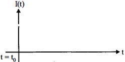
B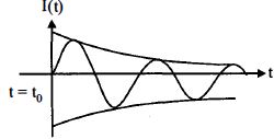
C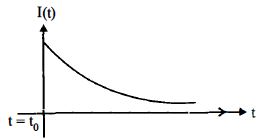
D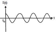
Solution
(D) In a series $LR$ circuit connected to an $AC$ voltage source $V(t) = V_0 \sin \omega t$,the current $I(t)$ is given by $I(t) = I_0 \sin(\omega t - \phi)$,where $I_0 = \frac{V_0}{Z}$ and $Z = \sqrt{R^2 + (\omega L)^2}$.
The transient part of the current,which involves the term $e^{-Rt/L}$,decays to zero as $t \to \infty$ because $t_0 \gg \frac{L}{R}$.
Therefore,after a very large time,only the steady-state sinusoidal current remains,which oscillates with the same frequency as the source voltage but with a phase lag $\phi = \tan^{-1}(\frac{\omega L}{R})$.
This corresponds to a steady-state sinusoidal oscillation.
0 likes
View Solution33
MediumMCQ
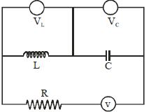
$A$ series $RLC$ circuit is shown here. The source frequency $f$ is varied, but the current is kept unchanged. Which of the curves showing changes of $V_C$ and $V_L$ with frequency would be valid for the circuit under consideration?
A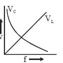
B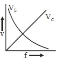
C
D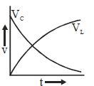
Solution
(A) In a series $RLC$ circuit, the voltage across the inductor is $V_L = I X_L = I (2 \pi f L)$ and the voltage across the capacitor is $V_C = I X_C = I \left( \frac{1}{2 \pi f C} \right)$.
Given that the current $I$ is kept constant as the frequency $f$ is varied.
From the expressions, we can see that $V_L \propto f$, which represents a straight line passing through the origin.
Also, $V_C \propto \frac{1}{f}$, which represents a rectangular hyperbola.
Therefore, the graph where $V_L$ increases linearly with $f$ and $V_C$ decreases hyperbolically with $f$ is the correct representation.
0 likes
View Solution34
DifficultMCQ
There is a $100\,\Omega$ resistance in an $L-C-R$ $AC$ circuit. An $AC$ $emf$ of $200\,V$ and $\omega = 300\,rad/s$ is applied to this circuit. When only the capacitor is removed,the current lags the voltage by $60^o$. When only the inductor is removed,the current leads the voltage by $60^o$. The current in this $L-C-R$ circuit will be.....$A$
A
$1$
B
$0.5$
C
$2$
D
$4$
Solution
(C) Given resistance $R = 100\,\Omega$,voltage $V = 200\,V$.
When the capacitor is removed,the circuit becomes an $L-R$ circuit. The phase angle $\phi = 60^o$ is given by $\tan 60^o = \frac{X_L}{R}$.
$\Rightarrow X_L = R \tan 60^o = 100 \times \sqrt{3} = 100\sqrt{3}\,\Omega$.
When the inductor is removed,the circuit becomes a $C-R$ circuit. The phase angle $\phi = 60^o$ is given by $\tan 60^o = \frac{X_C}{R}$.
$\Rightarrow X_C = R \tan 60^o = 100 \times \sqrt{3} = 100\sqrt{3}\,\Omega$.
Since $X_L = X_C$,the circuit is in resonance.
In resonance,the impedance $Z = R = 100\,\Omega$.
The current $I = \frac{V}{Z} = \frac{200}{100} = 2\,A$.
0 likes
View Solution35
MediumMCQ
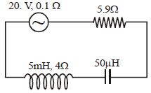
In the circuit shown in the figure, the source frequency is $\omega = 2000 \, rad/s$. The current in the circuit will be:
A
$2 \, A$
B
$3.3 \, A$
C
$2\sqrt{5} \, A$
D
$\sqrt{5} \, A$
Solution
(A) The total resistance $R$ of the circuit is the sum of all individual resistances: $R = 0.1 \, \Omega + 5.9 \, \Omega + 4 \, \Omega = 10 \, \Omega$.
The inductive reactance is $X_L = \omega L = 2000 \, rad/s \times 5 \times 10^{-3} \, H = 10 \, \Omega$.
The capacitive reactance is $X_C = \frac{1}{\omega C} = \frac{1}{2000 \, rad/s \times 50 \times 10^{-6} \, F} = \frac{1}{0.1} = 10 \, \Omega$.
The impedance $Z$ of the $LCR$ circuit is given by $Z = \sqrt{R^2 + (X_L - X_C)^2}$.
Substituting the values, $Z = \sqrt{10^2 + (10 - 10)^2} = \sqrt{100} = 10 \, \Omega$.
The current in the circuit is $I = \frac{V}{Z} = \frac{20 \, V}{10 \, \Omega} = 2 \, A$.
0 likes
View Solution36
MediumMCQ
The self-inductance of a choke coil is $10\, mH$. When it is connected to a $10\, V$ $dc$ source,the power loss is $20\, W$. When it is connected to a $10\, V$ $ac$ source,the power loss is $10\, W$. The frequency of the $ac$ source is......$Hz$.
A
$50$
B
$60$
C
$80$
D
$100$
Solution
(C) For $dc$ source: The inductor acts as a short circuit (resistance $R$ only). Power $P_{dc} = \frac{V^2}{R}$.
Given $V = 10\, V$ and $P_{dc} = 20\, W$,so $R = \frac{10^2}{20} = \frac{100}{20} = 5\, \Omega$.
For $ac$ source: The impedance $Z = \sqrt{R^2 + X_L^2}$,where $X_L = 2\pi f L$.
Power $P_{ac} = \frac{V^2 R}{Z^2} = \frac{V^2 R}{R^2 + X_L^2}$.
Given $P_{ac} = 10\, W$,so $10 = \frac{10^2 \times 5}{5^2 + X_L^2} \Rightarrow 10 = \frac{500}{25 + X_L^2}$.
$25 + X_L^2 = 50 \Rightarrow X_L^2 = 25 \Rightarrow X_L = 5\, \Omega$.
Since $X_L = 2\pi f L$,we have $5 = 2 \times 3.14 \times f \times (10 \times 10^{-3})$.
$f = \frac{5}{2 \times 3.14 \times 0.01} = \frac{5}{0.0628} \approx 79.6\, Hz \approx 80\, Hz$.
0 likes
View Solution37
DifficultMCQ
An $AC$ voltage source of $E = 150 \sin(100t)$ is used to run a device which offers a resistance of $20 \,\Omega$ and restricts the flow of current in one direction only. The $r.m.s.$ value of current in the circuit will be.....$A$
A
$1.58$
B
$0.98$
C
$3.75$
D
$2.38$
Solution
(C) The given voltage source is $E = 150 \sin(100t)$,where the peak voltage $V_0 = 150 \, V$.
The device acts as a half-wave rectifier,allowing current to flow only during the positive half-cycle of the $AC$ input.
For a half-wave rectified current,the $r.m.s.$ value is given by $i_{rms} = \frac{i_0}{2}$,where $i_0$ is the peak current.
The peak current is $i_0 = \frac{V_0}{R} = \frac{150}{20} = 7.5 \, A$.
Therefore,$i_{rms} = \frac{7.5}{2} = 3.75 \, A$.
0 likes
View Solution38
DifficultMCQ
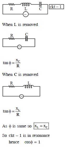
In an electrical circuit,$R, L, C$ and an $a.c.$ voltage source are all connected in series. When $L$ is removed from the circuit,the phase difference between the voltage and the current in the circuit is $\pi /3$. If instead,$C$ is removed from the circuit,the phase difference is again $\pi /3$. The power factor of the circuit is
A
$1$
B
$\sqrt{3}/2$
C
$0.5$
D
$1/\sqrt{2}$
Solution
(A) In an $R-L-C$ series circuit,the phase difference $\phi$ is given by $\tan \phi = \frac{|X_L - X_C|}{R}$.
When $L$ is removed,the circuit becomes an $R-C$ circuit. The phase difference is $\tan \phi = \frac{X_C}{R}$. Given $\phi = \pi/3$,we have $\tan(\pi/3) = \sqrt{3} = \frac{X_C}{R}$,so $X_C = R\sqrt{3}$.
When $C$ is removed,the circuit becomes an $R-L$ circuit. The phase difference is $\tan \phi = \frac{X_L}{R}$. Given $\phi = \pi/3$,we have $\tan(\pi/3) = \sqrt{3} = \frac{X_L}{R}$,so $X_L = R\sqrt{3}$.
Since $X_L = X_C$,the original $R-L-C$ circuit is in resonance.
At resonance,the impedance $Z = R$,and the phase difference $\phi = 0$.
The power factor is $\cos \phi = \cos(0) = 1$.
0 likes
View Solution39
EasyMCQ
Assertion: Ohm's law cannot be applied to $a.c.$ circuits.
Reason: Resistance offered by a capacitor for an $a.c.$ source depends upon the frequency of the source.
Reason: Resistance offered by a capacitor for an $a.c.$ source depends upon the frequency of the source.
A
If both Assertion and Reason are correct and the Reason is a correct explanation of the Assertion.
B
If both Assertion and Reason are correct but Reason is not a correct explanation of the Assertion.
C
If the Assertion is correct but Reason is incorrect.
D
If both the Assertion and Reason are incorrect.
Solution
(D) The Assertion is incorrect because Ohm's law $(V = IR)$ can be applied to $a.c.$ circuits using the concept of impedance $(Z)$. For an $a.c.$ circuit, the relation is $V = IZ$, where $Z$ is the impedance.
The Reason is also incorrect because the resistance offered by a capacitor is called capacitive reactance $(X_C)$, not resistance. While it is true that $X_C = 1 / (2\pi fC)$ depends on frequency, calling it 'resistance' is technically inaccurate in the context of general circuit theory, and the statement as a whole does not justify the false assertion.
The Reason is also incorrect because the resistance offered by a capacitor is called capacitive reactance $(X_C)$, not resistance. While it is true that $X_C = 1 / (2\pi fC)$ depends on frequency, calling it 'resistance' is technically inaccurate in the context of general circuit theory, and the statement as a whole does not justify the false assertion.
0 likes
View Solution40
EasyMCQ
Assertion: Long distance power transmission is done at high voltage.
Reason: At high voltage supply, power losses are less.
Reason: At high voltage supply, power losses are less.
A
If both Assertion and Reason are correct and the Reason is a correct explanation of the Assertion.
B
If both Assertion and Reason are correct but Reason is not a correct explanation of the Assertion.
C
If the Assertion is correct but Reason is incorrect.
D
If both the Assertion and Reason are incorrect.
Solution
(A) The power transmitted through a line is given by $P = VI$, where $V$ is the voltage and $I$ is the current.
The power loss in the transmission line due to resistance $R$ is given by $P_{\text{loss}} = I^2R$.
Substituting $I = \frac{P}{V}$, we get $P_{\text{loss}} = (\frac{P}{V})^2 R = \frac{P^2 R}{V^2}$.
From this expression, it is clear that $P_{\text{loss}} \propto \frac{1}{V^2}$.
Therefore, by increasing the voltage $V$, the power loss $P_{\text{loss}}$ decreases significantly.
Thus, both the Assertion and the Reason are correct, and the Reason is the correct explanation of the Assertion.
0 likes
View Solution41
EasyMCQ
Assertion : In the purely resistive element of a series $LCR$ $AC$ circuit,the maximum value of $rms$ current increases with an increase in the angular frequency of the applied $e.m.f$.
Reason : $I_{\max} = \frac{\varepsilon_{\max}}{Z}$,where $Z = \sqrt{R^2 + (\omega L - \frac{1}{\omega C})^2}$ and $I_{\max}$ is the peak current in a cycle.
Reason : $I_{\max} = \frac{\varepsilon_{\max}}{Z}$,where $Z = \sqrt{R^2 + (\omega L - \frac{1}{\omega C})^2}$ and $I_{\max}$ is the peak current in a cycle.
A
If both Assertion and Reason are correct and the Reason is a correct explanation of the Assertion.
B
If both Assertion and Reason are correct but Reason is not a correct explanation of the Assertion.
C
If the Assertion is correct but Reason is incorrect.
D
If both the Assertion and Reason are incorrect.
Solution
(D) The peak current in a series $LCR$ circuit is given by $I_{\max} = \frac{\varepsilon_{\max}}{Z}$,where $Z = \sqrt{R^2 + (\omega L - \frac{1}{\omega C})^2}$.
In a purely resistive element,the current is independent of frequency,but in a series $LCR$ circuit,the impedance $Z$ depends on the angular frequency $\omega$.
As $\omega$ increases,the term $(\omega L - \frac{1}{\omega C})^2$ changes. Specifically,the current $I_{\max}$ reaches its maximum value at resonance $(\omega = \frac{1}{\sqrt{LC}})$ and decreases as we move away from resonance in either direction.
Therefore,the assertion that the current always increases with an increase in angular frequency is incorrect.
The reason provided is a correct formula for peak current,but it does not support the false assertion.
Thus,the Assertion is incorrect and the Reason is correct.
0 likes
View Solution42
Medium
Answer the following questions:
$(a)$ In any $ac$ circuit, is the applied instantaneous voltage equal to the algebraic sum of the instantaneous voltages across the series elements of the circuit? Is the same true for $rms$ voltage?
$(b)$ Why is a capacitor used in the primary circuit of an induction coil?
$(c)$ An applied voltage signal consists of a superposition of a $dc$ voltage and an $ac$ voltage of high frequency. The circuit consists of an inductor and a capacitor in series. Show that the $dc$ signal will appear across $C$ and the $ac$ signal across $L$.
$(d)$ $A$ choke coil in series with a lamp is connected to a $dc$ line. The lamp is seen to shine brightly. Insertion of an iron core in the choke causes no change in the lamp's brightness. Predict the corresponding observations if the connection is to an $ac$ line.
$(e)$ Why is a choke coil needed in the use of fluorescent tubes with $ac$ mains? Why can we not use an ordinary resistor instead of the choke coil?
Solution
(N/A) Yes, the applied instantaneous voltage is equal to the algebraic sum of the instantaneous voltages across the series elements of the circuit due to Kirchhoff's Voltage Law. However, this is not true for $rms$ voltage because the voltages across different elements are generally not in phase.
$(b)$ $A$ capacitor is used in the primary circuit of an induction coil to prevent sparking at the contact breaker. When the circuit is broken, the rapid change in current induces a high back $emf$ in the primary coil, which would cause a spark across the contacts. The capacitor provides a path for the current, absorbing the energy and preventing the spark.
$(c)$ For a $dc$ signal, the frequency is $0$. The inductive reactance $X_L = 2\pi fL = 0$, while the capacitive reactance $X_C = 1/(2\pi fC) \to \infty$. Thus, the $dc$ voltage drops across $C$. For a high-frequency $ac$ signal, $X_L$ is very large and $X_C$ is very small. Thus, the $ac$ voltage drops across $L$.
$(d)$ If connected to an $ac$ line, the lamp will glow less brightly when an iron core is inserted. The iron core increases the inductance $L$ of the choke, which increases the inductive reactance $X_L = 2\pi fL$. This increases the total impedance of the circuit, reducing the current and thus the brightness of the lamp.
$(e)$ $A$ choke coil is used to limit the current in a fluorescent tube circuit without dissipating significant power, as it has a high reactance and low resistance. An ordinary resistor would dissipate power as heat $(I^2R)$, which is inefficient and wasteful.
0 likes
View Solution43
EasyMCQ
What is the reason we prefer $A.C.$ voltage over $D.C.$ voltage for power transmission?
A
$A.C.$ is cheaper to produce.
B
$A.C.$ voltage can be easily stepped up or down using transformers.
C
$A.C.$ is safer for human use.
D
$A.C.$ does not cause energy loss.
Solution
(B) The primary reason for preferring $A.C.$ voltage over $D.C.$ voltage for long-distance power transmission is the ease of voltage transformation.
Using a transformer,$A.C.$ voltage can be easily stepped up to a very high value for transmission,which significantly reduces the current $(I)$ flowing through the lines.
Since power loss in transmission lines is given by $P_{loss} = I^2R$,reducing the current leads to a drastic reduction in energy loss due to heating ($I^2R$ loss).
$D.C.$ voltage cannot be easily stepped up or down using simple transformers,making it inefficient for long-distance transmission.
0 likes
View Solution44
EasyMCQ
With which of the following is the relationship between the phase of current and voltage in an $AC$ circuit represented?
A
Phasor diagram
B
Vector diagram
C
Scalar diagram
D
None of these
Solution
(A) In an $AC$ circuit,the voltage and current are time-varying quantities that can be represented as rotating vectors.
These rotating vectors are known as phasors.
$A$ phasor diagram is a graphical representation that shows the phase relationship between the alternating current and voltage in an $AC$ circuit.
It helps in visualizing the phase difference $\phi$ between the voltage and current vectors,which is essential for analyzing $AC$ circuits containing resistors,inductors,and capacitors.
0 likes
View Solution45
MediumMCQ
Give the name of the physical quantity in an $LCR$ circuit that corresponds to displacement $x$ in forced oscillations.
A
Charge $q$
B
Current $i$
C
Voltage $V$
D
Inductance $L$
Solution
(A) In a mechanical system undergoing forced oscillations,the differential equation is given by $m \frac{d^2x}{dt^2} + b \frac{dx}{dt} + kx = F_0 \sin(\omega t)$.
In an $LCR$ series circuit,the differential equation for charge $q$ is given by $L \frac{d^2q}{dt^2} + R \frac{dq}{dt} + \frac{q}{C} = V_0 \sin(\omega t)$.
Comparing these two equations,we can see that the charge $q$ in the $LCR$ circuit is analogous to the displacement $x$ in the mechanical system.
Therefore,the physical quantity that corresponds to displacement $x$ is charge $q$.
0 likes
View Solution46
EasyMCQ
Give the name of the physical quantity in an $LCR$ circuit that corresponds to mass $m$ in forced oscillations.
A
Inductance $L$
B
Capacitance $C$
C
Resistance $R$
D
Frequency $\omega$
Solution
(A) In an $LCR$ series circuit,the differential equation for the charge $q$ is given by $L \frac{d^2q}{dt^2} + R \frac{dq}{dt} + \frac{q}{C} = E(t)$.
Comparing this with the equation for a forced mechanical oscillator,$m \frac{d^2x}{dt^2} + b \frac{dx}{dt} + kx = F(t)$,we can identify the analogous quantities.
The term involving the second derivative of the displacement $x$ is $m \frac{d^2x}{dt^2}$,which corresponds to $L \frac{d^2q}{dt^2}$ in the electrical circuit.
Therefore,the physical quantity that corresponds to mass $m$ is the self-inductance $L$.
0 likes
View Solution47
EasyMCQ
Give the name of the physical quantity in an $LCR$ circuit that corresponds to the damping constant in forced oscillations.
A
Resistance $(R)$
B
Inductance $(L)$
C
Capacitance $(C)$
D
Impedance $(Z)$
Solution
(A) In a mechanical system undergoing forced oscillations,the equation of motion is given by $m \frac{d^2x}{dt^2} + b \frac{dx}{dt} + kx = F_0 \cos(\omega t)$,where $b$ is the damping constant.
In an $LCR$ series circuit,the differential equation for the charge $q$ is $L \frac{d^2q}{dt^2} + R \frac{dq}{dt} + \frac{q}{C} = V_0 \cos(\omega t)$.
Comparing the two equations,we see that the term involving the first derivative of the variable (velocity $\frac{dx}{dt}$ in mechanics and current $I = \frac{dq}{dt}$ in circuits) represents the dissipative element.
Therefore,the resistance $R$ in an $LCR$ circuit corresponds to the damping constant $b$ in forced oscillations.
0 likes
View Solution48
Medium
An electrical device draws $2 \, kW$ power from $AC$ mains $(V_{rms} = 223 \, V = \sqrt{50000} \, V)$. The current lags in phase by $\tan \phi = -\frac{3}{4}$ compared to the voltage. Find $(i)$ $R$,$(ii)$ $X_C - X_L$,and $(iii)$ $I_M$. Another device has twice the values for $R$,$X_C$,and $X_L$. How are the answers affected?
Solution
(A) Given: Power $P = 2 \, kW = 2000 \, W$,$V_{rms} = 223 \, V$,$\tan \phi = -\frac{3}{4}$.
Since the current lags,the circuit is inductive,meaning $X_L > X_C$. Thus,$\tan \phi = \frac{X_L - X_C}{R} = \frac{3}{4}$.
$Z = \frac{V^2}{P} = \frac{223^2}{2000} = \frac{50000}{2000} = 25 \, \Omega$.
Using $Z^2 = R^2 + (X_L - X_C)^2$,we have $25^2 = R^2 + (\frac{3}{4}R)^2 = R^2 + \frac{9}{16}R^2 = \frac{25}{16}R^2$.
$625 = \frac{25}{16}R^2 \Rightarrow R^2 = 400 \Rightarrow R = 20 \, \Omega$.
$X_L - X_C = \frac{3}{4} \times 20 = 15 \, \Omega$. Therefore,$X_C - X_L = -15 \, \Omega$.
$I_M = \frac{V_m}{Z} = \frac{\sqrt{2} \times 223}{25} \approx 12.6 \, A$.
If $R, X_L, X_C$ are doubled,$Z' = \sqrt{(2R)^2 + (2(X_L - X_C))^2} = 2Z = 50 \, \Omega$.
$I' = \frac{V}{Z'} = \frac{I}{2} = 6.3 \, A$. Power $P' = V I' \cos \phi = \frac{P}{2} = 1 \, kW$.
0 likes
View SolutionAlternating Current — Mix Examples-Alternating Current · Frequently Asked Questions
1Are these Alternating Current questions useful for JEE and NEET?
Yes. All questions in this section are mapped to JEE Main and NEET exam patterns. Previous year questions from JEE Main, NEET, GUJCET and state-level exams are included with full solutions.
2Can I switch to Hindi or Gujarati for these questions?
Yes. Use the language tabs in the hero section or the sidebar to view the same questions and solutions in English, Hindi or Gujarati.
3How do I generate a question paper from this subtopic?
Use the Vedclass Exam Paper Generator — select the chapter and subtopic, set difficulty, and generate Sets A, B, C, D automatically. First 3 chapters of every subject are free.
Vedclass Products
For Students
Vedclass Test Series
Mock tests in real JEE/NEET style with performance analysis. 5-day free trial.
Start Free TrialFor Teachers
Exam Paper Generator
Generate Set A/B/C/D papers from this chapter in 2 minutes. 3 chapters free.
Try FreeFor Institutes
Online Exam Module
Live online exams with unlimited students, 360° analytics & white-label branding.
See DemoFor Teachers & Institutes
Generate a Alternating Current Exam Paper in 2 Minutes
Select subtopic & difficulty — Sets A, B, C, D auto-generated with No Repeat logic.
First 3 chapters of every subject are free — no payment required.