
A English
RL, RC and LC AC Circuits Questions in English
Class 12 Physics · Alternating Current · RL, RC and LC AC Circuits
281+
Questions
English
Language
100%
With Solutions
Showing 49 of 281 questions in English
1
MediumMCQ
If $L$ and $R$ are respectively the inductance and resistance,then the dimensions of $\frac{R}{L}$ will be
A
$T^2$
B
$T$
C
$T^{-1}$
D
$T^{-2}$
Solution
(C) The time constant of an $LR$ circuit is given by $\tau = \frac{L}{R}$.
This implies that the dimensions of $\frac{L}{R}$ are the same as the dimensions of time,i.e.,$[T]$.
Therefore,the dimensions of $\frac{R}{L}$ are the reciprocal of the dimensions of time.
Dimensions of $\frac{R}{L} = \frac{1}{[T]} = [T^{-1}]$.
This implies that the dimensions of $\frac{L}{R}$ are the same as the dimensions of time,i.e.,$[T]$.
Therefore,the dimensions of $\frac{R}{L}$ are the reciprocal of the dimensions of time.
Dimensions of $\frac{R}{L} = \frac{1}{[T]} = [T^{-1}]$.
0 likes
View Solution2
EasyMCQ
An alternating current of frequency $f$ is flowing in a circuit containing a resistance $R$ and a choke $L$ in series. The impedance of this circuit is
A
$R + 2\pi fL$
B
$\sqrt{R^2 + 4\pi^2 f^2 L^2}$
C
$\sqrt{R^2 + L^2}$
D
$\sqrt{R^2 + 2\pi fL}$
Solution
(B) In an $LR$ series circuit,the impedance $Z$ is given by the formula $Z = \sqrt{R^2 + X_L^2}$.
Here,$X_L$ is the inductive reactance,which is defined as $X_L = \omega L$.
Since the angular frequency $\omega = 2\pi f$,we can substitute this into the expression for $X_L$ to get $X_L = 2\pi fL$.
Substituting $X_L$ back into the impedance formula,we get $Z = \sqrt{R^2 + (2\pi fL)^2}$.
Therefore,$Z = \sqrt{R^2 + 4\pi^2 f^2 L^2}$.
0 likes
View Solution3
EasyMCQ
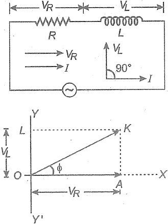
An alternating voltage is connected in series with a resistance $R$ and an inductance $L$. If the potential drop across the resistance is $200 \, V$ and across the inductance is $150 \, V$,then the applied voltage is.......$V$.
A
$350$
B
$250$
C
$500$
D
$300$
Solution
(B) In an $RL$ series circuit,the voltage across the resistor $(V_R)$ and the voltage across the inductor $(V_L)$ are out of phase by $90^{\circ}$.
Therefore,the total applied voltage $V$ is the phasor sum of $V_R$ and $V_L$,given by the formula:
$V = \sqrt{V_R^2 + V_L^2}$
Given $V_R = 200 \, V$ and $V_L = 150 \, V$.
Substituting the values:
$V = \sqrt{(200)^2 + (150)^2}$
$V = \sqrt{40000 + 22500}$
$V = \sqrt{62500}$
$V = 250 \, V$.
Therefore,the total applied voltage $V$ is the phasor sum of $V_R$ and $V_L$,given by the formula:
$V = \sqrt{V_R^2 + V_L^2}$
Given $V_R = 200 \, V$ and $V_L = 150 \, V$.
Substituting the values:
$V = \sqrt{(200)^2 + (150)^2}$
$V = \sqrt{40000 + 22500}$
$V = \sqrt{62500}$
$V = 250 \, V$.
0 likes
View Solution4
MediumMCQ
An inductive circuit contains a resistance of $10 \, \Omega$ and an inductance of $20 \, H$. If an $AC$ voltage of $120 \, V$ and frequency $60 \, Hz$ is applied to this circuit, the current would be nearly: (in $A$)
A
$0.32$
B
$0.016$
C
$0.48$
D
$0.80$
Solution
(B) The impedance $Z$ of an $RL$ series circuit is given by $Z = \sqrt{R^2 + X_L^2}$, where $X_L = 2\pi f L$.
Given: $R = 10 \, \Omega$, $L = 20 \, H$, $V = 120 \, V$, and $f = 60 \, Hz$.
First, calculate the inductive reactance $X_L = 2 \times \pi \times 60 \times 20 = 2400\pi \, \Omega$.
$X_L \approx 2400 \times 3.1416 \approx 7540 \, \Omega$.
Now, calculate the impedance $Z = \sqrt{10^2 + (7540)^2} \approx 7540 \, \Omega$.
The current $I = \frac{V}{Z} = \frac{120}{7540} \approx 0.0159 \, A$.
Rounding to the nearest value, $I \approx 0.016 \, A$.
0 likes
View Solution5
MediumMCQ
$20\,V$ $AC$ is applied to a circuit consisting of a resistance and a coil with negligible resistance. If the voltage across the resistance is $12\,V$,the voltage across the coil is.....$V$.
A
$16$
B
$10$
C
$8$
D
$6$
Solution
(A) In an $L-R$ series circuit,the total applied voltage $V$ is the phasor sum of the voltage across the resistor $V_R$ and the voltage across the inductor $V_L$.
The relationship is given by $V^2 = V_R^2 + V_L^2$.
Given: $V = 20\,V$ and $V_R = 12\,V$.
Substituting the values: $20^2 = 12^2 + V_L^2$.
$400 = 144 + V_L^2$.
$V_L^2 = 400 - 144 = 256$.
$V_L = \sqrt{256} = 16\,V$.
Therefore,the voltage across the coil is $16\,V$.
The relationship is given by $V^2 = V_R^2 + V_L^2$.
Given: $V = 20\,V$ and $V_R = 12\,V$.
Substituting the values: $20^2 = 12^2 + V_L^2$.
$400 = 144 + V_L^2$.
$V_L^2 = 400 - 144 = 256$.
$V_L = \sqrt{256} = 16\,V$.
Therefore,the voltage across the coil is $16\,V$.
0 likes
View Solution6
EasyMCQ
$A$ resistance of $300 \ \Omega$ and an inductance of $\frac{1}{\pi} \ H$ are connected in series to an $AC$ voltage of $20 \ V$ and $200 \ Hz$ frequency. The phase angle between the voltage and current is
A
$\tan^{-1} \frac{4}{3}$
B
$\tan^{-1} \frac{3}{4}$
C
$\tan^{-1} \frac{3}{2}$
D
$\tan^{-1} \frac{2}{5}$
Solution
(A) In an $LR$ series circuit,the phase angle $\phi$ between the voltage and current is given by the formula: $\tan \phi = \frac{X_L}{R}$.
Here,$R = 300 \ \Omega$,$L = \frac{1}{\pi} \ H$,and frequency $f = 200 \ Hz$.
The inductive reactance $X_L$ is calculated as: $X_L = 2\pi f L = 2\pi \times 200 \times \frac{1}{\pi} = 400 \ \Omega$.
Substituting the values into the phase angle formula:
$\tan \phi = \frac{400}{300} = \frac{4}{3}$.
Therefore,the phase angle is $\phi = \tan^{-1} \left( \frac{4}{3} \right)$.
0 likes
View Solution7
EasyMCQ
An alternating current source of frequency $100\, Hz$ is connected to a combination of a resistor,a capacitor,and an inductor in series. The potential difference across the inductor,the resistor,and the capacitor is $46\, V$,$8\, V$,and $40\, V$ respectively. The electromotive force $(EMF)$ of the alternating current source in volts is:
A
$94$
B
$14$
C
$10$
D
$76$
Solution
(C) In an $LCR$ series circuit,the potential difference across the inductor $(V_L)$,resistor $(V_R)$,and capacitor $(V_C)$ are given as $V_L = 46\, V$,$V_R = 8\, V$,and $V_C = 40\, V$.
The total $EMF$ $(V)$ of the source is given by the formula: $V = \sqrt{V_R^2 + (V_L - V_C)^2}$.
Substituting the given values: $V = \sqrt{8^2 + (46 - 40)^2}$.
$V = \sqrt{8^2 + 6^2} = \sqrt{64 + 36} = \sqrt{100} = 10\, V$.
Thus,the $EMF$ of the source is $10\, V$.
The total $EMF$ $(V)$ of the source is given by the formula: $V = \sqrt{V_R^2 + (V_L - V_C)^2}$.
Substituting the given values: $V = \sqrt{8^2 + (46 - 40)^2}$.
$V = \sqrt{8^2 + 6^2} = \sqrt{64 + 36} = \sqrt{100} = 10\, V$.
Thus,the $EMF$ of the source is $10\, V$.
0 likes
View Solution8
MediumMCQ
In an $L-R$ circuit,the value of $L$ is $(\frac{0.4}{\pi}) \, H$ and the value of $R$ is $30 \, \Omega$. If an alternating e.m.f. of $200 \, V$ at $50 \, Hz$ is connected to the circuit,what are the impedance and the current in the circuit?
A
$11.4 \, \Omega, 17.5 \, A$
B
$30.7 \, \Omega, 6.5 \, A$
C
$40.4 \, \Omega, 5 \, A$
D
$50 \, \Omega, 4 \, A$
Solution
(D) The impedance $Z$ of an $L-R$ circuit is given by $Z = \sqrt{R^2 + X_L^2}$,where $X_L = 2\pi fL$.
Given $R = 30 \, \Omega$,$f = 50 \, Hz$,and $L = \frac{0.4}{\pi} \, H$.
First,calculate the inductive reactance $X_L = 2\pi \times 50 \times \frac{0.4}{\pi} = 100 \times 0.4 = 40 \, \Omega$.
Now,calculate the impedance $Z = \sqrt{30^2 + 40^2} = \sqrt{900 + 1600} = \sqrt{2500} = 50 \, \Omega$.
The current $I$ in the circuit is given by $I = \frac{V}{Z} = \frac{200}{50} = 4 \, A$.
Thus,the impedance is $50 \, \Omega$ and the current is $4 \, A$.
0 likes
View Solution9
MediumMCQ
In a series $LCR$ circuit,operated with an $ac$ of angular frequency $\omega$,the total impedance is
A
${[{R^2} + {(L\omega - C\omega )^2}]^{1/2}}$
B
${\left[ {{R^2} + {{\left( {L\omega - \frac{1}{{C\omega }}} \right)}^2}} \right]^{1/2}}$
C
${\left[ {{R^2} + {{\left( {L\omega - \frac{1}{{C\omega }}} \right)}^2}} \right]^{ - 1/2}}$
D
${\left[ {{{(R\omega )}^2} + {{\left( {L\omega - \frac{1}{{C\omega }}} \right)}^2}} \right]^{1/2}}$
Solution
(B) In a series $LCR$ circuit,the impedance $Z$ is the vector sum of resistance $R$ and the net reactance $X = X_L - X_C$.
The inductive reactance is given by $X_L = L\omega$.
The capacitive reactance is given by $X_C = \frac{1}{C\omega}$.
The total impedance $Z$ is calculated using the formula:
$Z = \sqrt{R^2 + (X_L - X_C)^2}$
Substituting the values of $X_L$ and $X_C$ into the formula:
$Z = \sqrt{R^2 + \left(L\omega - \frac{1}{C\omega}\right)^2}$
This can be written as:
$Z = \left[R^2 + \left(L\omega - \frac{1}{C\omega}\right)^2\right]^{1/2}$
0 likes
View Solution10
MediumMCQ
An e.m.f. $E = 4 \cos(1000t) \, V$ is applied to an $LR$-circuit of inductance $3 \, mH$ and resistance $4 \, \Omega$. The amplitude of current in the circuit is:
A
$4/\sqrt{7}$
B
$1$
C
$4/7$
D
$0.8$
Solution
(D) The given e.m.f. is $E = E_0 \cos(\omega t)$,where $E_0 = 4 \, V$ and $\omega = 1000 \, rad/s$.
Given inductance $L = 3 \, mH = 3 \times 10^{-3} \, H$ and resistance $R = 4 \, \Omega$.
The inductive reactance is $X_L = \omega L = 1000 \times 3 \times 10^{-3} = 3 \, \Omega$.
The impedance of the $LR$-circuit is $Z = \sqrt{R^2 + X_L^2} = \sqrt{4^2 + 3^2} = \sqrt{16 + 9} = \sqrt{25} = 5 \, \Omega$.
The amplitude of the current $I_0$ is given by $I_0 = E_0 / Z = 4 / 5 = 0.8 \, A$.
0 likes
View Solution11
EasyMCQ
In an $AC$ circuit,a resistance of $R \, \Omega$ is connected in series with an inductance $L$. If the phase angle between voltage and current is $45^o$,the value of inductive reactance will be:
A
$\frac{R}{4}$
B
$\frac{R}{2}$
C
$R$
D
Cannot be found with the given data
Solution
(C) In an $RL$ series circuit,the phase angle $\phi$ between voltage and current is given by the formula: $\tan \phi = \frac{X_L}{R}$.
Given that the phase angle $\phi = 45^o$,we substitute this into the equation:
$\tan 45^o = \frac{X_L}{R}$.
Since $\tan 45^o = 1$,we have $1 = \frac{X_L}{R}$.
Therefore,$X_L = R$.
Given that the phase angle $\phi = 45^o$,we substitute this into the equation:
$\tan 45^o = \frac{X_L}{R}$.
Since $\tan 45^o = 1$,we have $1 = \frac{X_L}{R}$.
Therefore,$X_L = R$.
0 likes
View Solution12
MediumMCQ
When $100 \, V$ $DC$ is applied across a coil,a current of $1 \, A$ flows through it. When $100 \, V$ $AC$ at $50 \, Hz$ is applied to the same coil,only $0.5 \, A$ current flows. The impedance of the coil is ....... $\Omega$.
A
$100$
B
$200$
C
$300$
D
$400$
Solution
(B) When $DC$ is supplied,the coil acts as a pure resistor because the frequency is zero. Therefore,the resistance $R$ is given by $R = \frac{V}{I_{DC}} = \frac{100 \, V}{1 \, A} = 100 \, \Omega$.
When $AC$ is supplied,the coil offers both resistance and inductive reactance. The total opposition to the current is called impedance $(Z)$.
Using Ohm's law for $AC$ circuits,$Z = \frac{V}{I_{AC}} = \frac{100 \, V}{0.5 \, A} = 200 \, \Omega$.
Thus,the impedance of the coil is $200 \, \Omega$.
When $AC$ is supplied,the coil offers both resistance and inductive reactance. The total opposition to the current is called impedance $(Z)$.
Using Ohm's law for $AC$ circuits,$Z = \frac{V}{I_{AC}} = \frac{100 \, V}{0.5 \, A} = 200 \, \Omega$.
Thus,the impedance of the coil is $200 \, \Omega$.
0 likes
View Solution13
EasyMCQ
$A$ $12\,\Omega$ resistor and a $0.21\,H$ inductor are connected in series to an $ac$ source operating at $20\,V$,$50\,Hz$. The phase angle between the current and the source voltage is.....$^o$
A
$30$
B
$40$
C
$80$
D
$90$
Solution
(C) Given: Resistance $R = 12\,\Omega$,Inductance $L = 0.21\,H$,Frequency $f = 50\,Hz$.
The angular frequency is given by $\omega = 2\pi f = 2 \times \pi \times 50 = 100\pi\,rad/s$.
The inductive reactance is $X_L = \omega L = 100\pi \times 0.21 = 21\pi\,\Omega$.
Using $\pi \approx 3.14$,we get $X_L \approx 100 \times 3.14 \times 0.21 = 65.94\,\Omega$.
However,using the standard approximation $\pi \approx 22/7$,$X_L = 100 \times (22/7) \times 0.21 = 100 \times 22 \times 0.03 = 66\,\Omega$.
The phase angle $\phi$ in an $RL$ series circuit is given by $\tan \phi = \frac{X_L}{R}$.
$\tan \phi = \frac{66}{12} = 5.5$.
$\phi = \tan^{-1}(5.5) \approx 79.7^o \approx 80^o$.
0 likes
View Solution14
EasyMCQ
In an $ac$ circuit,the potential difference across an inductance and resistance joined in series are respectively $16\, V$ and $20\, V$. The total potential difference across the circuit is.......$V$
A
$20$
B
$25.6$
C
$31.9$
D
$53.5$
Solution
(B) In a series $LR$ circuit,the potential difference across the resistance $(V_R)$ and the inductance $(V_L)$ are in quadrature,meaning they differ in phase by $90^{\circ}$.
Given: $V_L = 16\, V$ and $V_R = 20\, V$.
The total potential difference $(V)$ across the circuit is given by the phasor sum:
$V = \sqrt{V_R^2 + V_L^2}$
Substituting the given values:
$V = \sqrt{(20)^2 + (16)^2}$
$V = \sqrt{400 + 256}$
$V = \sqrt{656}$
$V \approx 25.6\, V$.
Given: $V_L = 16\, V$ and $V_R = 20\, V$.
The total potential difference $(V)$ across the circuit is given by the phasor sum:
$V = \sqrt{V_R^2 + V_L^2}$
Substituting the given values:
$V = \sqrt{(20)^2 + (16)^2}$
$V = \sqrt{400 + 256}$
$V = \sqrt{656}$
$V \approx 25.6\, V$.
0 likes
View Solution15
EasyMCQ
$A$ $220\, V$,$50\, Hz$ $ac$ source is connected to an inductance of $0.2\, H$ and a resistance of $20\, \Omega$ in series. What is the current in the circuit (in $, A$)?
A
$10$
B
$5$
C
$33.3$
D
$3.33$
Solution
(D) Given: Voltage $V = 220\, V$,Frequency $f = 50\, Hz$,Inductance $L = 0.2\, H$,Resistance $R = 20\, \Omega$.
First,calculate the inductive reactance $X_L = 2 \pi f L = 2 \times 3.14 \times 50 \times 0.2 = 62.8\, \Omega$.
The impedance of the $LR$ series circuit is $Z = \sqrt{R^2 + X_L^2} = \sqrt{20^2 + 62.8^2} = \sqrt{400 + 3943.84} = \sqrt{4343.84} \approx 65.9\, \Omega$.
The current in the circuit is $I = \frac{V}{Z} = \frac{220}{65.9} \approx 3.33\, A$.
0 likes
View Solution16
MediumMCQ
In the circuit shown below,the $ac$ source has voltage $V = 20\cos (\omega t)$ volts with $\omega = 2000 \,rad/sec$. The amplitude of the current will be nearest to:
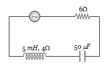
A
$2$
B
$3.3$
C
$2/\sqrt{5}$
D
$\sqrt{5}$
Solution
(A) Given: $V = 20\cos(2000t) \,V$,so $V_0 = 20 \,V$ and $\omega = 2000 \,rad/s$.
The circuit consists of a resistor $R_1 = 6 \,\Omega$ in series with an inductor of $L = 5 \,mH$ having internal resistance $R_2 = 4 \,\Omega$,and a capacitor $C = 50 \,\mu F$.
Total resistance $R = R_1 + R_2 = 6 + 4 = 10 \,\Omega$.
Inductive reactance $X_L = \omega L = 2000 \times 5 \times 10^{-3} = 10 \,\Omega$.
Capacitive reactance $X_C = \frac{1}{\omega C} = \frac{1}{2000 \times 50 \times 10^{-6}} = \frac{1}{0.1} = 10 \,\Omega$.
Impedance $Z = \sqrt{R^2 + (X_L - X_C)^2} = \sqrt{10^2 + (10 - 10)^2} = 10 \,\Omega$.
Amplitude of current $i_0 = \frac{V_0}{Z} = \frac{20}{10} = 2 \,A$.
0 likes
View Solution17
EasyMCQ
In an $ac$ circuit,the reactance of a coil is $\sqrt{3}$ times its resistance. The phase difference between the voltage across the coil and the current through the coil will be:
A
$\pi /3$
B
$\pi /2$
C
$\pi /4$
D
$\pi /6$
Solution
(A) In an $ac$ circuit containing a coil (inductor with resistance),the phase difference $\phi$ between the voltage and the current is given by the formula $\tan \phi = \frac{X_L}{R}$.
Given that the reactance $X_L = \sqrt{3} R$.
Substituting this into the formula,we get $\tan \phi = \frac{\sqrt{3} R}{R} = \sqrt{3}$.
Since $\tan \phi = \sqrt{3}$,the phase angle $\phi = 60^{\circ}$.
Converting degrees to radians,$\phi = 60^{\circ} \times \frac{\pi}{180^{\circ}} = \frac{\pi}{3}$.
Given that the reactance $X_L = \sqrt{3} R$.
Substituting this into the formula,we get $\tan \phi = \frac{\sqrt{3} R}{R} = \sqrt{3}$.
Since $\tan \phi = \sqrt{3}$,the phase angle $\phi = 60^{\circ}$.
Converting degrees to radians,$\phi = 60^{\circ} \times \frac{\pi}{180^{\circ}} = \frac{\pi}{3}$.
0 likes
View Solution18
MediumMCQ
In an $ac$ circuit,the current lags behind the voltage by $\pi /3$. The components in the circuit are
A
$R$ and $L$
B
$R$ and $C$
C
$L$ and $C$
D
Only $R$
Solution
(A) In an $ac$ circuit,if the current lags behind the voltage by a phase angle $\phi$,the circuit must be an inductive circuit containing a resistor $(R)$ and an inductor $(L)$.
In an $RL$ series circuit,the voltage across the resistor $(V_R)$ is in phase with the current $(I)$,while the voltage across the inductor $(V_L)$ leads the current by $90^\circ$.
The resultant voltage $V$ leads the current by a phase angle $\phi$,which is given by:
$\tan \phi = \frac{V_L}{V_R} = \frac{I_0 X_L}{I_0 R} = \frac{X_L}{R}$
Since the current lags behind the voltage,the circuit must contain $R$ and $L$.
0 likes
View Solution19
EasyMCQ
$A$ resistance of $40\, \Omega$ and an inductance of $95.5\, \text{mH}$ are connected in series in a $50\, \text{Hz}$ $AC$ circuit. The impedance of this combination is very nearly.....$\Omega$.
A
$30$
B
$40$
C
$50$
D
$60$
Solution
(C) The impedance $Z$ of an $RL$ series circuit is given by the formula: $Z = \sqrt{R^2 + X_L^2}$,where $X_L = 2\pi \nu L$.
Given: $R = 40\, \Omega$,$L = 95.5\, \text{mH} = 95.5 \times 10^{-3}\, \text{H}$,and $\nu = 50\, \text{Hz}$.
First,calculate the inductive reactance $X_L$:
$X_L = 2 \times 3.1416 \times 50 \times 95.5 \times 10^{-3} \approx 30\, \Omega$.
Now,calculate the impedance $Z$:
$Z = \sqrt{40^2 + 30^2} = \sqrt{1600 + 900} = \sqrt{2500} = 50\, \Omega$.
0 likes
View Solution20
MediumMCQ
There is a $5\,\Omega$ resistance in an $AC$ circuit. An inductance of $0.1\,H$ is connected in series with it. If the equation of the $AC$ $EMF$ is $E = 5\sin(50t)$,then the phase difference between the current and the $EMF$ is:
A
$\frac{\pi}{2}$
B
$\frac{\pi}{6}$
C
$\frac{\pi}{4}$
D
$0$
Solution
(C) Given: Resistance $R = 5\,\Omega$,Inductance $L = 0.1\,H$,and angular frequency $\omega = 50\,rad/s$.
In an $LR$ series circuit,the phase difference $\phi$ between the current and the $EMF$ is given by $\tan \phi = \frac{X_L}{R}$.
First,calculate the inductive reactance $X_L = \omega L = 50 \times 0.1 = 5\,\Omega$.
Now,substitute the values into the formula: $\tan \phi = \frac{5}{5} = 1$.
Therefore,$\phi = \tan^{-1}(1) = \frac{\pi}{4}$.
0 likes
View Solution21
EasyMCQ
An inductor of inductance $L$ and a resistor of resistance $R$ are joined in series and connected to a source of frequency $\omega$. The power dissipated in the circuit is
A
$\frac{R^2 + \omega^2 L^2}{V}$
B
$\frac{V^2 R}{R^2 + \omega^2 L^2}$
C
$\frac{V}{R^2 + \omega^2 L^2}$
D
$\frac{\sqrt{R^2 + \omega^2 L^2}}{V^2}$
Solution
(B) The impedance $Z$ of an $LR$ series circuit is given by $Z = \sqrt{R^2 + X_L^2} = \sqrt{R^2 + (\omega L)^2} = \sqrt{R^2 + \omega^2 L^2}$.
Power dissipated in an $AC$ circuit is given by $P = V_{rms} I_{rms} \cos \phi$.
Since $I_{rms} = \frac{V_{rms}}{Z}$ and the power factor $\cos \phi = \frac{R}{Z}$, we substitute these into the power formula:
$P = V_{rms} \left( \frac{V_{rms}}{Z} \right) \left( \frac{R}{Z} \right) = \frac{V_{rms}^2 R}{Z^2}$.
Substituting $Z^2 = R^2 + \omega^2 L^2$, we get:
$P = \frac{V^2 R}{R^2 + \omega^2 L^2}$.
0 likes
View Solution22
EasyMCQ
$A$ coil of $200 \, \Omega$ resistance and $1.0 \, H$ inductance is connected to an $ac$ source of frequency $200/2\pi \, Hz.$ The phase angle between potential and current will be.....$^o$
A
$30$
B
$90$
C
$45$
D
$0$
Solution
(C) The phase angle $\phi$ in an $RL$ circuit is given by the formula $\tan \phi = \frac{X_L}{R}$.
Here, the inductive reactance $X_L = 2\pi \nu L$.
Given: Resistance $R = 200 \, \Omega$, Inductance $L = 1.0 \, H$, and Frequency $\nu = \frac{200}{2\pi} \, Hz$.
Substituting the values: $X_L = 2\pi \times \left( \frac{200}{2\pi} \right) \times 1 = 200 \, \Omega$.
Now, $\tan \phi = \frac{200}{200} = 1$.
Therefore, $\phi = \tan^{-1}(1) = 45^o$.
0 likes
View Solution23
MediumMCQ
$A$ coil has $L = 0.04 \, H$ and $R = 12 \, \Omega$. When it is connected to a $220 \, V$,$50 \, Hz$ supply,the current flowing through the coil in amperes is: (in $.7$)
A
$10$
B
$11$
C
$14$
D
$12$
Solution
(D) The impedance $Z$ of an $LR$ circuit is given by $Z = \sqrt{R^2 + X_L^2}$,where $X_L = 2\pi \nu L$.
Given $R = 12 \, \Omega$,$L = 0.04 \, H$,$\nu = 50 \, Hz$,and $V = 220 \, V$.
First,calculate the inductive reactance: $X_L = 2 \times 3.14 \times 50 \times 0.04 = 12.56 \, \Omega$.
Now,calculate the impedance: $Z = \sqrt{12^2 + 12.56^2} = \sqrt{144 + 157.75} = \sqrt{301.75} \approx 17.37 \, \Omega$.
The current $I$ is given by $I = \frac{V}{Z} = \frac{220}{17.37} \approx 12.66 \, A \approx 12.7 \, A$.
0 likes
View Solution24
EasyMCQ
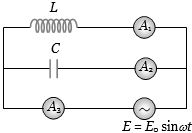
An inductor $L$ and a capacitor $C$ are connected in the circuit as shown in the figure. The frequency of the power supply is equal to the resonant frequency of the circuit. Which ammeter will read zero ampere?
A
$A_1$
B
$A_2$
C
$A_3$
D
None of these
Solution
(C) In the given circuit,the inductor $L$ and capacitor $C$ are connected in parallel with an $AC$ power supply.
At resonance,the inductive reactance $X_L = \omega L$ and capacitive reactance $X_C = \frac{1}{\omega C}$ are equal,i.e.,$X_L = X_C$.
In a parallel $LC$ circuit at resonance,the current flowing through the inductor branch $(I_L)$ and the current flowing through the capacitor branch $(I_C)$ are equal in magnitude but opposite in phase (phase difference of $180^{\circ}$).
Therefore,the total current $I$ supplied by the source is $I = I_L + I_C = 0$.
Ammeter $A_3$ is placed in the main line to measure the total current supplied by the source.
Since the total current is zero at resonance,ammeter $A_3$ will read zero ampere.
0 likes
View Solution25
MediumMCQ
In a circuit,$L, C$ and $R$ are connected in series with an alternating voltage source of frequency $f$. The current leads the voltage by $45^o$. The value of $C$ is
A
$\frac{1}{2\pi f(2\pi fL + R)}$
B
$\frac{1}{\pi f(2\pi fL + R)}$
C
$\frac{1}{2\pi f(2\pi fL - R)}$
D
$\frac{1}{\pi f(2\pi fL - R)}$
Solution
(A) The phase angle $\phi$ in an $LCR$ series circuit is given by $\tan \phi = \frac{X_C - X_L}{R}$.
Since the current leads the voltage,the circuit is capacitive,and the phase angle is $\phi = -45^o$ (or we use the magnitude of the lead as $\tan(45^o) = \frac{X_C - X_L}{R}$).
Substituting the values: $\tan 45^o = \frac{\frac{1}{2\pi fC} - 2\pi fL}{R}$.
Since $\tan 45^o = 1$,we have $1 = \frac{\frac{1}{2\pi fC} - 2\pi fL}{R}$.
$R = \frac{1}{2\pi fC} - 2\pi fL$.
$\frac{1}{2\pi fC} = 2\pi fL + R$.
Therefore,$C = \frac{1}{2\pi f(2\pi fL + R)}$.
0 likes
View Solution26
MediumMCQ
When $100 \, V$ $DC$ is supplied across a solenoid,a current of $1.0 \, A$ flows in it. When $100 \, V$ $AC$ is applied across the same coil,the current drops to $0.5 \, A$. If the frequency of the $AC$ source is $50 \, Hz$,then the impedance and inductance of the solenoid are:
A
$200 \, \Omega$ and $0.55 \, H$
B
$100 \, \Omega$ and $0.86 \, H$
C
$200 \, \Omega$ and $1.0 \, H$
D
$100 \, \Omega$ and $0.93 \, H$
Solution
(A) For $DC$,the solenoid acts as a pure resistor $R$. Given $V = 100 \, V$ and $I = 1.0 \, A$,we have $R = \frac{V}{I} = \frac{100}{1} = 100 \, \Omega$.
For $AC$,the solenoid acts as an $LR$ circuit with impedance $Z$. Given $V = 100 \, V$ and $I = 0.5 \, A$,we have $Z = \frac{V}{I} = \frac{100}{0.5} = 200 \, \Omega$.
The impedance is given by $Z = \sqrt{R^2 + X_L^2}$,where $X_L = 2\pi f L$.
Substituting the values: $200 = \sqrt{100^2 + (2 \cdot \pi \cdot 50 \cdot L)^2}$.
Squaring both sides: $40000 = 10000 + (100\pi L)^2$.
$30000 = (100\pi L)^2$.
Taking the square root: $100\sqrt{3} = 100\pi L$.
$L = \frac{\sqrt{3}}{\pi} \approx \frac{1.732}{3.1416} \approx 0.55 \, H$.
0 likes
View Solution27
MediumMCQ
In an $LR$-circuit,the inductive reactance is equal to the resistance $R$ of the circuit. An e.m.f. $E = E_0 \cos(\omega t)$ is applied to the circuit. The power consumed in the circuit is:
A
$\frac{E_0^2}{R}$
B
$\frac{E_0^2}{2R}$
C
$\frac{E_0^2}{4R}$
D
$\frac{E_0^2}{8R}$
Solution
(C) The average power consumed in an $AC$ circuit is given by $P = E_{rms} I_{rms} \cos \phi$,where $\cos \phi$ is the power factor.
We know that $E_{rms} = \frac{E_0}{\sqrt{2}}$ and $I_{rms} = \frac{I_0}{\sqrt{2}} = \frac{E_0}{Z\sqrt{2}}$.
The power factor is $\cos \phi = \frac{R}{Z}$.
Substituting these values,we get $P = \left(\frac{E_0}{\sqrt{2}}\right) \left(\frac{E_0}{Z\sqrt{2}}\right) \left(\frac{R}{Z}\right) = \frac{E_0^2 R}{2Z^2}$.
Given that the inductive reactance $X_L = R$,the impedance $Z$ is calculated as $Z = \sqrt{R^2 + X_L^2} = \sqrt{R^2 + R^2} = \sqrt{2}R$.
Substituting $Z^2 = 2R^2$ into the power formula: $P = \frac{E_0^2 R}{2(2R^2)} = \frac{E_0^2 R}{4R^2} = \frac{E_0^2}{4R}$.
0 likes
View Solution28
DifficultMCQ
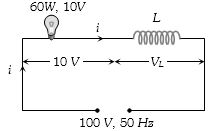
$A$ $10\, V, 60\, W$ bulb is to be connected to a $100\, V, 50\, Hz$ $AC$ source. To operate the bulb at its rated power,an induction coil is connected in series with it. Calculate the required self-inductance of the coil.
A
$0.052\, H$
B
$2.42\, H$
C
$16.2\, mH$
D
$1.62\, mH$
Solution
(A) The rated current of the bulb is $i = \frac{P}{V} = \frac{60}{10} = 6\, A$.
In an $RL$ series circuit,the supply voltage $V$ is related to the voltage across the bulb $V_R$ and the voltage across the inductor $V_L$ by $V = \sqrt{V_R^2 + V_L^2}$.
Given $V = 100\, V$ and $V_R = 10\, V$,we have $100^2 = 10^2 + V_L^2$.
$V_L^2 = 10000 - 100 = 9900$.
$V_L = \sqrt{9900} \approx 99.5\, V$.
The inductive reactance is $X_L = \frac{V_L}{i} = \frac{99.5}{6} \approx 16.58\, \Omega$.
Since $X_L = 2\pi f L$,we have $L = \frac{X_L}{2\pi f} = \frac{16.58}{2 \times 3.14 \times 50} = \frac{16.58}{314} \approx 0.0528\, H$.
Thus,the required self-inductance is approximately $0.052\, H$.
0 likes
View Solution29
MediumMCQ
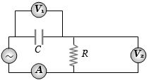
The diagram shows a capacitor $C$ and a resistor $R$ connected in series to an $ac$ source. $V_1$ and $V_2$ are voltmeters and $A$ is an ammeter. Consider the following statements:
$I$. Readings in $A$ and $V_2$ are always in phase.
$II$. Reading in $V_1$ lags behind the reading in $V_2$ by $\frac{\pi}{2}$.
$III$. Readings in $A$ and $V_1$ are always in phase.
Which of these statements is/are correct?
$I$. Readings in $A$ and $V_2$ are always in phase.
$II$. Reading in $V_1$ lags behind the reading in $V_2$ by $\frac{\pi}{2}$.
$III$. Readings in $A$ and $V_1$ are always in phase.
Which of these statements is/are correct?
A
$I$ only
B
$II$ only
C
$I$ and $II$ only
D
$II$ and $III$ only
Solution
(C) In an $RC$ series circuit,the current $I$ flows through both the resistor $R$ and the capacitor $C$.
$1$. The voltage across the resistor ($V_R$,measured by $V_2$) is always in phase with the current ($I$,measured by $A$). Thus,statement $I$ is correct.
$2$. The voltage across the capacitor ($V_C$,measured by $V_1$) lags behind the current by $\frac{\pi}{2}$.
$3$. Since $V_R$ is in phase with $I$,and $V_C$ lags behind $I$ by $\frac{\pi}{2}$,it follows that $V_C$ lags behind $V_R$ by $\frac{\pi}{2}$. This means $V_R$ is ahead of $V_C$ by $\frac{\pi}{2}$. Therefore,statement $II$ is correct.
$4$. Statement $III$ is incorrect because $V_1$ (voltage across capacitor) lags behind the current $A$ by $\frac{\pi}{2}$.
Thus,both statements $I$ and $II$ are correct.
0 likes
View Solution30
DifficultMCQ
An $ac$ source of angular frequency $\omega$ is connected across a resistor $R$ and a capacitor $C$ in series. The current registered is $I$. If the frequency of the source is changed to $\omega/3$ (while maintaining the same voltage),the current in the circuit is found to be halved. Calculate the ratio of reactance to resistance at the original frequency $\omega$.
A
$\sqrt{3/5}$
B
$\sqrt{2/5}$
C
$\sqrt{1/5}$
D
$\sqrt{4/5}$
Solution
(A) At angular frequency $\omega$,the current $I$ in the $RC$ series circuit is given by:
$I = \frac{V}{\sqrt{R^2 + X_C^2}} = \frac{V}{\sqrt{R^2 + (1/\omega C)^2}}$ ......$(i)$
When the frequency is changed to $\omega' = \omega/3$,the new capacitive reactance becomes $X_C' = \frac{1}{(\omega/3)C} = 3X_C$. The new current $I'$ is given as $I/2$:
$I/2 = \frac{V}{\sqrt{R^2 + (3X_C)^2}}$ ......$(ii)$
Dividing equation $(i)$ by equation $(ii)$:
$2 = \frac{\sqrt{R^2 + 9X_C^2}}{\sqrt{R^2 + X_C^2}}$
Squaring both sides:
$4 = \frac{R^2 + 9X_C^2}{R^2 + X_C^2}$
$4R^2 + 4X_C^2 = R^2 + 9X_C^2$
$3R^2 = 5X_C^2$
$\frac{X_C^2}{R^2} = \frac{3}{5}$
$\frac{X_C}{R} = \sqrt{\frac{3}{5}}$
0 likes
View Solution31
DifficultMCQ
$A$ virtual current of $4 \, A$ and $50 \, Hz$ flows in an $AC$ circuit containing a coil. The power consumed in the coil is $240 \, W$. If the virtual voltage across the coil is $100 \, V$,its inductance will be:
A
$\frac{1}{3\pi} \, H$
B
$\frac{1}{5\pi} \, H$
C
$\frac{1}{7\pi} \, H$
D
$\frac{1}{9\pi} \, H$
Solution
(B) Given: $I_{rms} = 4 \, A$,$f = 50 \, Hz$,$P = 240 \, W$,$V_{rms} = 100 \, V$.
Power consumed in the coil is given by $P = I_{rms}^2 R$.
$R = \frac{P}{I_{rms}^2} = \frac{240}{4^2} = \frac{240}{16} = 15 \, \Omega$.
Impedance of the coil is $Z = \frac{V_{rms}}{I_{rms}} = \frac{100}{4} = 25 \, \Omega$.
We know that $Z^2 = R^2 + X_L^2$,where $X_L = 2\pi f L$.
$X_L = \sqrt{Z^2 - R^2} = \sqrt{25^2 - 15^2} = \sqrt{625 - 225} = \sqrt{400} = 20 \, \Omega$.
Since $X_L = 2\pi f L$,we have $20 = 2 \times \pi \times 50 \times L$.
$L = \frac{20}{100\pi} = \frac{1}{5\pi} \, H$.
0 likes
View Solution32
DifficultMCQ
For a series $LCR$ circuit,$R = X_L = 2X_C$. The impedance of the circuit and the phase difference between $V$ and $i$ will be:
A
$\frac{\sqrt{5}R}{2}, \tan^{-1}(2)$
B
$\frac{\sqrt{5}R}{2}, \tan^{-1}\left(\frac{1}{2}\right)$
C
$\sqrt{5}X_C, \tan^{-1}(2)$
D
$\sqrt{5}R, \tan^{-1}\left(\frac{1}{2}\right)$
Solution
(B) Given: $R = X_L$ and $X_L = 2X_C$,which implies $X_C = \frac{R}{2}$.
The impedance $Z$ of a series $LCR$ circuit is given by $Z = \sqrt{R^2 + (X_L - X_C)^2}$.
Substituting the values: $Z = \sqrt{R^2 + (R - \frac{R}{2})^2} = \sqrt{R^2 + (\frac{R}{2})^2} = \sqrt{R^2 + \frac{R^2}{4}} = \sqrt{\frac{5R^2}{4}} = \frac{\sqrt{5}R}{2}$.
The phase difference $\phi$ is given by $\tan \phi = \frac{X_L - X_C}{R}$.
Substituting the values: $\tan \phi = \frac{R - R/2}{R} = \frac{R/2}{R} = \frac{1}{2}$.
Therefore,$\phi = \tan^{-1}\left(\frac{1}{2}\right)$.
Thus,the impedance is $\frac{\sqrt{5}R}{2}$ and the phase difference is $\tan^{-1}\left(\frac{1}{2}\right)$.
0 likes
View Solution33
MediumMCQ
The figure shows the variation of $R$,$X_L$,and $X_C$ with frequency $f$ in a series $LCR$ circuit. For which frequency point is the circuit inductive?
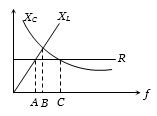
A
$A$
B
$B$
C
$C$
D
All points
Solution
(C) In a series $LCR$ circuit,the circuit is inductive when the inductive reactance is greater than the capacitive reactance,i.e.,$X_L > X_C$.
At point $A$: $X_C > X_L$,so the circuit is capacitive.
At point $B$: $X_C = X_L$,which is the resonance condition,so the circuit is purely resistive.
At point $C$: $X_L > X_C$,so the circuit is inductive.
Therefore,the correct option is $C$.
At point $A$: $X_C > X_L$,so the circuit is capacitive.
At point $B$: $X_C = X_L$,which is the resonance condition,so the circuit is purely resistive.
At point $C$: $X_L > X_C$,so the circuit is inductive.
Therefore,the correct option is $C$.
0 likes
View Solution34
MediumMCQ
An alternating emf is applied across a parallel combination of a resistance $R$,capacitance $C$ and an inductance $L$. If $I_R$,$I_L$,and $I_C$ are the currents through $R$,$L$,and $C$ respectively,then the diagram which correctly represents the phase relationship among $I_R$,$I_L$,$I_C$,and the source emf $E$ is:
A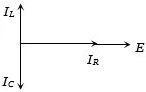
B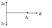
C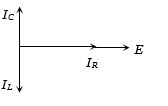
D
Solution
(C) In a parallel $RLC$ circuit,the same alternating emf $E$ is applied across each component.
$1$. The current $I_R$ through the resistor is in phase with the applied emf $E$.
$2$. The current $I_L$ through the inductor lags behind the applied emf $E$ by a phase angle of $\frac{\pi}{2}$.
$3$. The current $I_C$ through the capacitor leads the applied emf $E$ by a phase angle of $\frac{\pi}{2}$.
Comparing these relationships with the given diagrams,in option $C$,$I_R$ is in phase with $E$,$I_C$ is directed upwards (leading by $\frac{\pi}{2}$),and $I_L$ is directed downwards (lagging by $\frac{\pi}{2}$). Thus,the diagram in option $C$ correctly represents the phase relationships.
0 likes
View Solution35
MediumMCQ
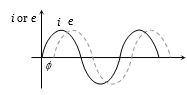
When an $AC$ source of $e.m.f.$ $e = E_0 \sin(100t)$ is connected across a circuit,the phase difference between the $e.m.f.$ $e$ and the current $i$ in the circuit is observed to be $\pi/4$,as shown in the diagram. If the circuit consists possibly only of $RC$ or $LC$ in series,find the relationship between the two elements.
A
$R = 1 \text{ k}\Omega, C = 10 \mu\text{F}$
B
$R = 1 \text{ k}\Omega, C = 1 \mu\text{F}$
C
$R = 1 \text{ k}\Omega, L = 10 \text{ H}$
D
$R = 1 \text{ k}\Omega, L = 1 \text{ H}$
Solution
(A) From the given diagram,the current $i$ leads the voltage $e$ by a phase angle $\phi = \pi/4$. This indicates that the circuit is an $RC$ series circuit.
For an $RC$ circuit,the phase angle $\phi$ is given by $\tan \phi = \frac{X_C}{R} = \frac{1}{\omega CR}$.
Given $\phi = \pi/4$,we have $\tan(\pi/4) = 1$,so $1 = \frac{1}{\omega CR}$,which implies $\omega CR = 1$.
Given $\omega = 100 \text{ rad/s}$,we have $100 \times C \times R = 1$,or $CR = 1/100 = 0.01 \text{ s}$.
Checking option $(A)$: $R = 1000 \, \Omega$ and $C = 10 \times 10^{-6} \text{ F} = 10^{-5} \text{ F}$.
Then $CR = 1000 \times 10^{-5} = 10^{-2} = 0.01 \text{ s}$.
This matches the condition,so option $(A)$ is correct.
0 likes
View Solution36
MediumMCQ
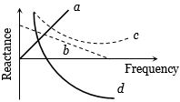
Which of the following plots may represent the reactance of a series $LC$ combination?
A
$a$
B
$b$
C
$c$
D
$d$
Solution
(A) The net reactance $X$ of a series $LC$ circuit is given by the difference between the inductive reactance $X_L$ and the capacitive reactance $X_C$.
$X = X_L - X_C = 2\pi fL - \frac{1}{2\pi fC}$.
As the frequency $f$ increases,$X_L = 2\pi fL$ increases linearly,while $X_C = \frac{1}{2\pi fC}$ decreases hyperbolically.
At low frequencies,$X_C$ dominates,making the net reactance negative.
At high frequencies,$X_L$ dominates,making the net reactance positive.
At the resonant frequency $f_0 = \frac{1}{2\pi\sqrt{LC}}$,the net reactance is zero.
The curve that starts from negative values,passes through zero,and increases towards positive values as frequency increases represents this behavior. Looking at the provided graph,none of the curves $a, b, c, d$ perfectly represent the standard $X$ vs $f$ plot for a series $LC$ circuit,but in many textbook contexts for this specific problem,the curve that shows a transition from negative to positive values is sought. However,based on the provided image,curve $a$ represents $X_L$,curve $d$ represents $X_C$,and curve $b$ is a linear decrease. None of the curves correctly represent the $LC$ series reactance curve,which should be a hyperbola-like curve crossing the frequency axis. Given the options provided in standard sources for this specific question,the intended answer is often associated with the curve that crosses the axis.
0 likes
View Solution37
DifficultMCQ
$A$ capacitor of $\frac{2.5}{\pi} \mu F$ and a resistor of $3000 \, \Omega$ are connected in series with a $200 \, V, 50 \, Hz$ $AC$ source. What are the power factor and the power dissipated,respectively?
A
$0.6, 0.06 \, W$
B
$0.06, 0.6 \, W$
C
$0.6, 4.8 \, W$
D
$4.8, 0.6 \, W$
Solution
(C) Given: $C = \frac{2.5}{\pi} \times 10^{-6} \, F$,$R = 3000 \, \Omega$,$V_{rms} = 200 \, V$,$\nu = 50 \, Hz$.
First,calculate the capacitive reactance $X_C$:
$X_C = \frac{1}{2\pi \nu C} = \frac{1}{2\pi \times 50 \times (\frac{2.5}{\pi} \times 10^{-6})} = \frac{1}{250 \times 10^{-6}} = 4000 \, \Omega$.
Calculate the impedance $Z$:
$Z = \sqrt{R^2 + X_C^2} = \sqrt{3000^2 + 4000^2} = \sqrt{9 \times 10^6 + 16 \times 10^6} = \sqrt{25 \times 10^6} = 5000 \, \Omega$.
Calculate the power factor $\cos \phi$:
$\cos \phi = \frac{R}{Z} = \frac{3000}{5000} = 0.6$.
Calculate the power dissipated $P$:
$P = \frac{V_{rms}^2 \cos \phi}{Z} = \frac{200^2 \times 0.6}{5000} = \frac{40000 \times 0.6}{5000} = 8 \times 0.6 = 4.8 \, W$.
0 likes
View Solution38
MediumMCQ
$A$ coil has an inductance of $10 \, mH$. When it is connected to a $10 \, V \, dc$ source,the power dissipation is $20 \, W$. When it is connected to a $10 \, V \, ac$ source,the power dissipation is $10 \, W$. What is the frequency of the $ac$ source in $Hz$?
A
$50$
B
$60$
C
$80$
D
$100$
Solution
(C) For $dc$ source: $P = \frac{V^2}{R}$. Given $V = 10 \, V$ and $P = 20 \, W$,we have $R = \frac{V^2}{P} = \frac{10^2}{20} = \frac{100}{20} = 5 \, \Omega$.
For $ac$ source: $P = I_{rms}^2 R = \left( \frac{V}{Z} \right)^2 R = \frac{V^2 R}{Z^2}$. Given $V = 10 \, V$ and $P = 10 \, W$,we have $Z^2 = \frac{V^2 R}{P} = \frac{10^2 \times 5}{10} = 50 \, \Omega^2$.
The impedance of an $RL$ circuit is $Z^2 = R^2 + X_L^2 = R^2 + (2 \pi \nu L)^2$.
Substituting the values: $50 = 5^2 + (2 \pi \nu \times 10 \times 10^{-3})^2$.
$50 = 25 + (2 \pi \nu \times 10^{-2})^2$.
$25 = (2 \pi \nu \times 10^{-2})^2$.
Taking the square root: $5 = 2 \pi \nu \times 10^{-2}$.
$\nu = \frac{5}{2 \pi \times 10^{-2}} = \frac{500}{2 \pi} \approx \frac{500}{6.28} \approx 79.6 \, Hz \approx 80 \, Hz$.
0 likes
View Solution39
MediumMCQ
The power factor of an $RL$ circuit is $1/2$. If $R = 100 \, \Omega$,what is the value of $L$? The frequency of the $AC$ source is $50 \, Hz$.
A
$\frac{\sqrt{3}}{\pi} \, H$
B
$\pi \, H$
C
$\frac{\pi}{\sqrt{3}} \, H$
D
None of these
Solution
(A) The power factor of an $RL$ circuit is given by $\cos \phi = \frac{R}{Z} = \frac{1}{2}$.
Since $\cos \phi = 1/2$,the phase angle $\phi = 60^\circ$.
We know that $\tan \phi = \frac{X_L}{R} = \frac{\omega L}{R}$.
Substituting the values: $\tan 60^\circ = \frac{2 \pi f L}{R}$.
$\sqrt{3} = \frac{2 \pi \times 50 \times L}{100}$.
$\sqrt{3} = \frac{100 \pi L}{100}$.
$\sqrt{3} = \pi L$.
Therefore,$L = \frac{\sqrt{3}}{\pi} \, H$.
0 likes
View Solution40
EasyMCQ
In an $RL$ circuit,the resistance is $\pi \sqrt{3} \,\Omega$. The phase difference between the current and the voltage is $30^\circ$. The $ac$ frequency is $50 \,Hz$. The inductance is . . . . . . $Henry$.
A
$0.5$
B
$0.03$
C
$0.05$
D
$0.01$
Solution
(D) The phase difference $\varphi$ in an $RL$ circuit is given by $\tan \varphi = \frac{X_L}{R}$.
Given: $R = \pi \sqrt{3} \,\Omega$,$\varphi = 30^\circ$,and $\nu = 50 \,Hz$.
We know that $X_L = 2\pi \nu L$.
Substituting the values into the formula: $\tan 30^\circ = \frac{2\pi \nu L}{R}$.
$\frac{1}{\sqrt{3}} = \frac{2\pi \times 50 \times L}{\pi \sqrt{3}}$.
Canceling $\pi \sqrt{3}$ from both sides: $\frac{1}{\sqrt{3}} = \frac{100L}{\sqrt{3}}$.
$1 = 100L$.
$L = \frac{1}{100} = 0.01 \,H$.
0 likes
View Solution41
MediumMCQ
In an $RL$ circuit,the current is $i = 100 \sin(314t) \ A$ and the voltage is $e = 200 \sin(314t + \pi/3) \ V$. If the resistance is $1 \ \Omega$,what is the reactance?
A
$-200\sqrt{3} \ \Omega$
B
$\sqrt{3} \ \Omega$
C
$-200/\sqrt{3} \ \Omega$
D
$100\sqrt{3} \ \Omega$
Solution
(B) Given: Current $i = 100 \sin(314t) \ A$ and Voltage $e = 200 \sin(314t + \pi/3) \ V$.
From the peak values,the peak current $I_0 = 100 \ A$ and peak voltage $V_0 = 200 \ V$.
The impedance $Z$ is given by $Z = V_0 / I_0 = 200 / 100 = 2 \ \Omega$.
In an $RL$ circuit,the impedance is related to resistance $R$ and reactance $X_L$ by the formula $Z^2 = R^2 + X_L^2$.
Given $R = 1 \ \Omega$,we have $2^2 = 1^2 + X_L^2$.
$4 = 1 + X_L^2 \implies X_L^2 = 3$.
Therefore,$X_L = \sqrt{3} \ \Omega$.
0 likes
View Solution42
MediumMCQ
In an $RL$ circuit,the reactance of the coil is $\sqrt{3}$ times the resistance. The phase difference between the voltage and the current is:
A
$\pi /3$
B
$\pi /2$
C
$\pi /4$
D
$\pi /6$
Solution
(A) In an $RL$ series circuit,the phase difference $\varphi$ between the voltage and the current is given by the formula: $\tan \varphi = \frac{X_L}{R}$.
Given that the reactance $X_L = \sqrt{3} R$.
Substituting this into the formula: $\tan \varphi = \frac{\sqrt{3} R}{R} = \sqrt{3}$.
Since $\tan \varphi = \sqrt{3}$,we have $\varphi = 60^{\circ}$.
Converting degrees to radians: $\varphi = 60^{\circ} \times \frac{\pi}{180^{\circ}} = \frac{\pi}{3}$ radians.
0 likes
View Solution43
DifficultMCQ
$A$ resistor and a capacitor are connected in series with an $AC$ source of angular frequency $\omega$. If the frequency is changed to $\omega / 3$ while keeping the voltage constant,the current becomes half. What is the ratio of the reactance to the resistance at the initial frequency?
A
$\sqrt{3/5}$
B
$\sqrt{2/5}$
C
$\sqrt{1/5}$
D
$\sqrt{4/5}$
Solution
(A) The current in an $RC$ series circuit is given by $I = \frac{V}{\sqrt{R^2 + X_C^2}}$,where $X_C = \frac{1}{\omega C}$.
At initial frequency $\omega$,$I = \frac{V}{\sqrt{R^2 + (1/\omega C)^2}}$ ... $(i)$
At frequency $\omega' = \omega/3$,the new reactance is $X_C' = \frac{1}{(\omega/3)C} = \frac{3}{\omega C} = 3X_C$.
The new current is $I' = I/2 = \frac{V}{\sqrt{R^2 + (3X_C)^2}}$ ... (ii)
Dividing $(i)$ by (ii),we get $2 = \frac{\sqrt{R^2 + 9X_C^2}}{\sqrt{R^2 + X_C^2}}$.
Squaring both sides: $4 = \frac{R^2 + 9X_C^2}{R^2 + X_C^2}$.
$4R^2 + 4X_C^2 = R^2 + 9X_C^2$.
$3R^2 = 5X_C^2$.
$\frac{X_C^2}{R^2} = \frac{3}{5}$.
Therefore,the ratio $\frac{X_C}{R} = \sqrt{\frac{3}{5}}$.
0 likes
View Solution44
MediumMCQ
$A$ resistor of $300 \Omega$ and an inductor of $\frac{1}{\pi} \text{ H}$ are connected in series with a $20 \text{ V}$,$200 \text{ Hz}$ $AC$ source. What is the phase difference between the current and the voltage?
A
$\tan^{-1} \frac{4}{3}$
B
$\tan^{-1} \frac{3}{4}$
C
$\tan^{-1} \frac{3}{2}$
D
$\tan^{-1} \frac{2}{5}$
Solution
(A) The phase difference $\phi$ in an $RL$ series circuit is given by $\tan \phi = \frac{X_L}{R}$.
Here,$R = 300 \Omega$,$L = \frac{1}{\pi} \text{ H}$,and $f = 200 \text{ Hz}$.
The inductive reactance is $X_L = \omega L = 2\pi f L$.
Substituting the values: $X_L = 2\pi \times 200 \times \frac{1}{\pi} = 400 \Omega$.
Now,$\tan \phi = \frac{400}{300} = \frac{4}{3}$.
Therefore,the phase difference is $\phi = \tan^{-1} \frac{4}{3}$.
0 likes
View Solution45
DifficultMCQ
In an $LR$-circuit,the inductive reactance is equal to the resistance $R$. If the applied voltage is $E = E_0 \cos(\omega t)$,what is the power dissipated in the circuit?
A
$\frac{E_0^2}{R}$
B
$\frac{E_0^2}{2R}$
C
$\frac{E_0^2}{4R}$
D
$\frac{E_0^2}{8R}$
Solution
(C) The average power in an $AC$ circuit is given by $P = E_{rms} I_{rms} \cos \phi$.
Here,$E_{rms} = \frac{E_0}{\sqrt{2}}$ and $I_{rms} = \frac{I_0}{\sqrt{2}} = \frac{E_0}{Z\sqrt{2}}$.
The power factor is $\cos \phi = \frac{R}{Z}$.
Substituting these,$P = \frac{E_0}{\sqrt{2}} \times \frac{E_0}{Z\sqrt{2}} \times \frac{R}{Z} = \frac{E_0^2 R}{2Z^2}$.
Given that the inductive reactance $X_L = R$,the impedance $Z = \sqrt{R^2 + X_L^2} = \sqrt{R^2 + R^2} = \sqrt{2}R$.
Substituting $Z^2 = 2R^2$ into the power formula:
$P = \frac{E_0^2 R}{2(2R^2)} = \frac{E_0^2 R}{4R^2} = \frac{E_0^2}{4R}$.
0 likes
View Solution46
MediumMCQ
When a current of $4 A$ at $50 Hz$ is passed through a coil,the power consumed by the coil is $240 W$. If the voltage of the $AC$ source is $100 V$,what is the inductance of the coil?
A
$\frac{1}{3\pi} H$
B
$\frac{1}{5\pi} H$
C
$\frac{1}{7\pi} H$
D
$\frac{1}{9\pi} H$
Solution
(B) The power consumed in an $AC$ circuit is given by $P = I_{rms}^2 R$.
Given $P = 240 W$ and $I_{rms} = 4 A$,we have $R = \frac{P}{I_{rms}^2} = \frac{240}{16} = 15 \Omega$.
The impedance $Z$ of the circuit is given by $Z = \frac{V_{rms}}{I_{rms}} = \frac{100}{4} = 25 \Omega$.
We know that $Z^2 = R^2 + X_L^2$,where $X_L$ is the inductive reactance.
$X_L = \sqrt{Z^2 - R^2} = \sqrt{25^2 - 15^2} = \sqrt{625 - 225} = \sqrt{400} = 20 \Omega$.
Since $X_L = 2\pi f L$,we have $20 = 2\pi(50)L$.
$L = \frac{20}{100\pi} = \frac{1}{5\pi} H$.
0 likes
View Solution47
MediumMCQ
Which of the following dimensions will be the same as that of time?
A
$\frac{C}{L}$
B
$\frac{L}{R}$
C
$LC$
D
$\frac{R}{L}$
Solution
(B) The dimension of resistance $R$ is $[M L^2 T^{-3} I^{-2}]$.
The dimension of inductance $L$ is $[M L^2 T^{-2} I^{-2}]$.
The dimension of capacitance $C$ is $[M^{-1} L^{-2} T^4 I^2]$.
Checking option $B$:
$\frac{L}{R} = \frac{[M L^2 T^{-2} I^{-2}]}{[M L^2 T^{-3} I^{-2}]} = [T^1] = T$.
Checking option $C$:
$\sqrt{LC} = \sqrt{[M L^2 T^{-2} I^{-2}] \cdot [M^{-1} L^{-2} T^4 I^2]} = \sqrt{[T^2]} = [T^1] = T$.
Since both $B$ and $C$ result in the dimension of time,the question implies identifying expressions with time dimensions. Given the standard format,both $\frac{L}{R}$ and $\sqrt{LC}$ are correct.
0 likes
View Solution48
EasyMCQ
An $ac$ voltage is applied to a resistance $R$ and an inductor $L$ in series. If $R$ and the inductive reactance are both equal to $3\,\Omega$,the phase difference between the applied voltage and the current in the circuit is
A
$\frac{\pi}{6}$
B
$\frac{\pi}{4}$
C
$\frac{\pi}{2}$
D
zero
Solution
(B) Given: Resistance $R = 3\,\Omega$ and Inductive reactance $X_L = 3\,\Omega$.
In an $LR$ series circuit,the phase difference $\phi$ between the applied voltage and the current is given by the formula:
$\tan \phi = \frac{X_L}{R}$
Substituting the given values:
$\tan \phi = \frac{3\,\Omega}{3\,\Omega} = 1$
Therefore,the phase difference is:
$\phi = \tan^{-1}(1) = \frac{\pi}{4}$ radians.
0 likes
View Solution49
DifficultMCQ
$A$ coil has resistance $30\,\Omega$ and inductive reactance $20\,\Omega$ at $50\,Hz$ frequency. If an $AC$ source of $200\,V, 100\,Hz$ is connected across the coil,the current in the coil will be ......$A$
A
$2$
B
$4$
C
$8$
D
$\frac{20}{\sqrt{13}}$
Solution
(B) Given: Resistance $R = 30\,\Omega$.
Inductive reactance $X_L = 20\,\Omega$ at frequency $f = 50\,Hz$.
Since $X_L = 2\pi f L$,the inductive reactance is directly proportional to the frequency $(X_L \propto f)$.
At a new frequency $f' = 100\,Hz$,the new inductive reactance $X_L'$ is:
$X_L' = X_L \times \left(\frac{f'}{f}\right) = 20\,\Omega \times \left(\frac{100\,Hz}{50\,Hz}\right) = 40\,\Omega$.
The impedance $Z$ of the $RL$ circuit is given by $Z = \sqrt{R^2 + (X_L')^2}$.
$Z = \sqrt{30^2 + 40^2} = \sqrt{900 + 1600} = \sqrt{2500} = 50\,\Omega$.
The current $I$ in the coil is $I = \frac{V}{Z} = \frac{200\,V}{50\,\Omega} = 4\,A$.
0 likes
View SolutionAlternating Current — RL, RC and LC AC Circuits · Frequently Asked Questions
1Are these Alternating Current questions useful for JEE and NEET?
Yes. All questions in this section are mapped to JEE Main and NEET exam patterns. Previous year questions from JEE Main, NEET, GUJCET and state-level exams are included with full solutions.
2Can I switch to Hindi or Gujarati for these questions?
Yes. Use the language tabs in the hero section or the sidebar to view the same questions and solutions in English, Hindi or Gujarati.
3How do I generate a question paper from this subtopic?
Use the Vedclass Exam Paper Generator — select the chapter and subtopic, set difficulty, and generate Sets A, B, C, D automatically. First 3 chapters of every subject are free.
Vedclass Products
For Students
Vedclass Test Series
Mock tests in real JEE/NEET style with performance analysis. 5-day free trial.
Start Free TrialFor Teachers
Exam Paper Generator
Generate Set A/B/C/D papers from this chapter in 2 minutes. 3 chapters free.
Try FreeFor Institutes
Online Exam Module
Live online exams with unlimited students, 360° analytics & white-label branding.
See DemoFor Teachers & Institutes
Generate a Alternating Current Exam Paper in 2 Minutes
Select subtopic & difficulty — Sets A, B, C, D auto-generated with No Repeat logic.
First 3 chapters of every subject are free — no payment required.