
A English
RL, RC and LC AC Circuits Questions in English
Class 12 Physics · Alternating Current · RL, RC and LC AC Circuits
281+
Questions
English
Language
100%
With Solutions
Showing 50 of 281 questions in English
201
DifficultMCQ
In an $LR$ circuit of $3 \text{ mH}$ inductance and $4 \text{ } \Omega$ resistance,an $\text{emf } E = 4 \cos(1000t) \text{ V}$ is applied. The amplitude of the current is:
A
$0.8 \text{ A}$
B
$\frac{4}{7} \text{ A}$
C
$1.0 \text{ A}$
D
$\frac{4}{\sqrt{7}} \text{ A}$
Solution
(A) The given $\text{emf}$ is $E = E_{0} \cos(\omega t)$,where $E_{0} = 4 \text{ V}$ and $\omega = 1000 \text{ rad/s}$.
The impedance $Z$ of an $LR$ circuit is given by $Z = \sqrt{R^{2} + X_{L}^{2}}$,where $X_{L} = \omega L$.
Given $R = 4 \text{ } \Omega$,$L = 3 \text{ mH} = 3 \times 10^{-3} \text{ H}$,and $\omega = 1000 \text{ rad/s}$.
First,calculate the inductive reactance $X_{L} = \omega L = 1000 \times 3 \times 10^{-3} = 3 \text{ } \Omega$.
Now,calculate the impedance $Z = \sqrt{4^{2} + 3^{2}} = \sqrt{16 + 9} = \sqrt{25} = 5 \text{ } \Omega$.
The amplitude of the current $i_{0}$ is given by $i_{0} = \frac{E_{0}}{Z} = \frac{4}{5} = 0.8 \text{ A}$.
0 likes
View Solution202
MediumMCQ
In an $L-R$ circuit,the inductive reactance is equal to $\sqrt{3}$ times the resistance $R$ of the circuit. An e.m.f. $E = E_0 \sin(\omega t)$ is applied to the circuit. The power consumed in the circuit is:
A
$\frac{E_0^2}{4 R}$
B
$\frac{E_0^2}{6 R}$
C
$\frac{E_0^2}{8 R}$
D
$\frac{E_0^2}{12 R}$
Solution
(C) Given that the inductive reactance $X_L = \sqrt{3} R$.
The impedance $Z$ of the $L-R$ circuit is given by $Z = \sqrt{R^2 + X_L^2}$.
Substituting $X_L = \sqrt{3} R$,we get $Z = \sqrt{R^2 + (\sqrt{3} R)^2} = \sqrt{R^2 + 3R^2} = \sqrt{4R^2} = 2R$.
The peak current in the circuit is $I_0 = \frac{E_0}{Z} = \frac{E_0}{2R}$.
The average power consumed in an $AC$ circuit is given by $P = I_{rms}^2 R = \left(\frac{I_0}{\sqrt{2}}\right)^2 R$.
Substituting $I_0 = \frac{E_0}{2R}$,we get $P = \frac{1}{2} \left(\frac{E_0}{2R}\right)^2 R = \frac{1}{2} \cdot \frac{E_0^2}{4R^2} \cdot R = \frac{E_0^2}{8R}$.
0 likes
View Solution203
MediumMCQ
$A$ coil of resistance $450 \Omega$ and self-inductance $1.5 \text{ H}$ is connected to an $A$.$C$. source of frequency $\frac{150}{\pi} \text{ Hz}$. The phase difference between voltage and current is
A
$\tan^{-1}(0.5)$
B
$\tan^{-1}(1)$
C
$\tan^{-1}(1.5)$
D
$\tan^{-1}(2.0)$
Solution
(B) Given: Resistance $R = 450 \Omega$,Inductance $L = 1.5 \text{ H}$,Frequency $f = \frac{150}{\pi} \text{ Hz}$.
The inductive reactance $X_L$ is given by $X_L = \omega L = 2\pi f L$.
Substituting the values: $X_L = 2 \pi \times \left(\frac{150}{\pi}\right) \times 1.5 = 2 \times 150 \times 1.5 = 300 \times 1.5 = 450 \Omega$.
The phase difference $\phi$ between voltage and current in an $RL$ circuit is given by $\tan \phi = \frac{X_L}{R}$.
Substituting the values: $\tan \phi = \frac{450}{450} = 1$.
Therefore,$\phi = \tan^{-1}(1)$.
0 likes
View Solution204
MediumMCQ
$A$ resistance of $200 \ \Omega$ and an inductor of $\frac{1}{2 \pi} \ H$ are connected in series to an a.c. voltage of $40 \ V$ and $100 \ Hz$ frequency. The phase angle between the voltage and current is
A
$\tan^{-1}(1/5)$
B
$\tan^{-1}(1/4)$
C
$\tan^{-1}(1/3)$
D
$\tan^{-1}(0.5)$
Solution
(D) Given: Resistance $R = 200 \ \Omega$,Inductance $L = \frac{1}{2 \pi} \ H$,Frequency $f = 100 \ Hz$.
The inductive reactance is given by $X_L = 2 \pi f L$.
Substituting the values: $X_L = 2 \pi \times 100 \times \frac{1}{2 \pi} = 100 \ \Omega$.
The phase angle $\phi$ in an $RL$ series circuit is given by $\tan \phi = \frac{X_L}{R}$.
Substituting the values: $\tan \phi = \frac{100}{200} = \frac{1}{2} = 0.5$.
Therefore,the phase angle is $\phi = \tan^{-1}(0.5)$.
0 likes
View Solution205
MediumMCQ
An ideal inductor of $\left(\frac{1}{\pi}\right) H$ is connected in series with a $300 \Omega$ resistor. If a $20 \ V, 200 \ Hz$ alternating source is connected across the combination,the phase difference between the voltage and current is
A
$\tan^{-1}\left(\frac{3}{4}\right)$
B
$\tan^{-1}\left(\frac{4}{3}\right)$
C
$\tan^{-1}\left(\frac{5}{4}\right)$
D
$\tan^{-1}\left(\frac{4}{5}\right)$
Solution
(B) The given values are: Inductance $L = \frac{1}{\pi} \ H$,Resistance $R = 300 \ \Omega$,Frequency $f = 200 \ Hz$.
First,calculate the inductive reactance $X_L = 2\pi f L$.
$X_L = 2 \times \pi \times 200 \times \frac{1}{\pi} = 400 \ \Omega$.
The phase difference $\phi$ in an $LR$ series circuit is given by $\tan \phi = \frac{X_L}{R}$.
Substituting the values,$\tan \phi = \frac{400}{300} = \frac{4}{3}$.
Therefore,$\phi = \tan^{-1}\left(\frac{4}{3}\right)$.
0 likes
View Solution206
EasyMCQ
In an $A.C.$ circuit,a resistance '$R$' is connected in series with an inductance '$L$'. If the phase angle between voltage and current is $45^{\circ}$,the value of inductive reactance will be $(\tan 45^{\circ} = 1)$.
A
$R$
B
$\frac{R}{2}$
C
$\frac{R}{4}$
D
$\frac{R}{\sqrt{2}}$
Solution
(A) In an $L-R$ series circuit,the phase angle $\phi$ between voltage and current is given by the formula: $\tan \phi = \frac{X_L}{R}$.
Given that the phase angle $\phi = 45^{\circ}$ and $\tan 45^{\circ} = 1$.
Substituting these values into the formula: $1 = \frac{X_L}{R}$.
Therefore,$X_L = R$.
Thus,the inductive reactance is equal to the resistance $R$.
Given that the phase angle $\phi = 45^{\circ}$ and $\tan 45^{\circ} = 1$.
Substituting these values into the formula: $1 = \frac{X_L}{R}$.
Therefore,$X_L = R$.
Thus,the inductive reactance is equal to the resistance $R$.
0 likes
View Solution207
EasyMCQ
An $a.c.$ circuit contains a resistance of $12 \ \Omega$ and an inductor of inductive reactance $5 \ \Omega$. The phase angle between current and potential difference will be
A
$\sin ^{-1}\left(\frac{12}{13}\right)$
B
$\cos ^{-1}\left(\frac{5}{12}\right)$
C
$\sin ^{-1}\left(\frac{5}{12}\right)$
D
$\cos ^{-1}\left(\frac{12}{13}\right)$
Solution
(D) In an $LR$ series circuit, the phase angle $\phi$ between the current and the potential difference is given by the formula: $\tan \phi = \frac{X_L}{R}$.
Given: Resistance $R = 12 \ \Omega$ and inductive reactance $X_L = 5 \ \Omega$.
Substituting the values: $\tan \phi = \frac{5}{12}$.
This implies $\phi = \tan^{-1}\left(\frac{5}{12}\right)$.
To express this in terms of $\sin$ or $\cos$, we consider a right-angled triangle with opposite side $5$ and adjacent side $12$. The hypotenuse is $\sqrt{5^2 + 12^2} = \sqrt{25 + 144} = \sqrt{169} = 13$.
Therefore, $\sin \phi = \frac{\text{opposite}}{\text{hypotenuse}} = \frac{5}{13}$, which means $\phi = \sin^{-1}\left(\frac{5}{13}\right)$.
Also, $\cos \phi = \frac{\text{adjacent}}{\text{hypotenuse}} = \frac{12}{13}$, which means $\phi = \cos^{-1}\left(\frac{12}{13}\right)$.
Comparing this with the given options, the correct option is $\cos^{-1}\left(\frac{12}{13}\right)$.
0 likes
View Solution208
MediumMCQ
An e.m.f. $E=E_0 \cos \omega t$ is applied to a circuit containing $L$ and $R$ in series. If $X_L=2 R$,then the power dissipated in the circuit is
A
$\frac{E_0^2}{12 R}$
B
$\frac{E_0^2}{10 R}$
C
$\frac{E_0^2}{8 R}$
D
$\frac{E_0^2}{6 R}$
Solution
(B) The impedance $Z$ of an $LR$ series circuit is given by $Z = \sqrt{R^2 + X_L^2}$.
Given $X_L = 2R$,we have $Z^2 = R^2 + (2R)^2 = R^2 + 4R^2 = 5R^2$.
The average power dissipated in an $AC$ circuit is given by $P = V_{rms} I_{rms} \cos \phi$,where $\cos \phi = \frac{R}{Z}$ is the power factor.
Since $V_{rms} = \frac{E_0}{\sqrt{2}}$ and $I_{rms} = \frac{V_{rms}}{Z} = \frac{E_0}{\sqrt{2}Z}$,the power is $P = \frac{E_0}{\sqrt{2}} \times \frac{E_0}{\sqrt{2}Z} \times \frac{R}{Z} = \frac{E_0^2 R}{2 Z^2}$.
Substituting $Z^2 = 5R^2$,we get $P = \frac{E_0^2 R}{2(5R^2)} = \frac{E_0^2 R}{10 R^2} = \frac{E_0^2}{10 R}$.
0 likes
View Solution209
MediumMCQ
An e.m.f. $E = E_0 \cos \omega t$ is applied to an $L-R$ circuit. The inductive reactance is equal to the resistance $R$ of the circuit. The power consumed in the circuit is:
A
$\frac{E_0^2}{\sqrt{2} R}$
B
$\frac{E_0^2}{2 R}$
C
$\frac{E_0^2}{4 R}$
D
$\frac{E_0^2}{R}$
Solution
(C) The average power consumed in an $AC$ circuit is given by $P = E_{rms} I_{rms} \cos \phi$.
Here,the power factor is $\cos \phi = \frac{R}{Z}$.
The $rms$ current is $I_{rms} = \frac{E_{rms}}{Z} = \frac{E_0}{\sqrt{2} Z}$.
Substituting these into the power formula:
$P = \left( \frac{E_0}{\sqrt{2}} \right) \left( \frac{E_0}{\sqrt{2} Z} \right) \left( \frac{R}{Z} \right) = \frac{E_0^2 R}{2 Z^2} \dots (i)$.
Given that the inductive reactance $X_L = R$,the impedance $Z$ of the $L-R$ circuit is:
$Z = \sqrt{R^2 + X_L^2} = \sqrt{R^2 + R^2} = \sqrt{2} R$.
Substituting $Z^2 = 2 R^2$ into equation $(i)$:
$P = \frac{E_0^2 R}{2 (2 R^2)} = \frac{E_0^2 R}{4 R^2} = \frac{E_0^2}{4 R}$.
0 likes
View Solution210
EasyMCQ
An electric lamp connected in series with a capacitor and an $A.C.$ source is glowing with a certain brightness. On increasing the value of capacitance,the brightness of the lamp
A
is increased.
B
is decreased.
C
remains the same.
D
becomes zero.
Solution
(A) The capacitive reactance is given by $X_{C} = \frac{1}{2 \pi f C}$.
If the capacitance $(C)$ is increased,the capacitive reactance $(X_{C})$ will decrease.
The total impedance $(Z)$ of the circuit is given by $Z = \sqrt{R^2 + X_{C}^2}$.
As $X_{C}$ decreases,the total impedance $(Z)$ of the circuit decreases.
According to Ohm's law for $A.C.$ circuits,the current $(I = V/Z)$ will increase.
Since the brightness of the lamp depends on the power dissipated $(P = I^2 R)$,an increase in current leads to an increase in the brightness of the lamp.
0 likes
View Solution211
DifficultMCQ
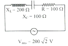
In the given circuit, the r.m.s. value of the current through the resistor $R$ is:
A
$2 \, A$
B
$0.5 \, A$
C
$20 \, A$
D
$2 \sqrt{2} \, A$
Solution
(A) The circuit is an $LCR$ series circuit with $X_L = 200 \, \Omega$, $X_C = 100 \, \Omega$, $R = 100 \, \Omega$, and $V_{rms} = 200 \sqrt{2} \, V$.
The impedance $Z$ of the circuit is given by:
$Z = \sqrt{R^2 + (X_L - X_C)^2}$
$Z = \sqrt{100^2 + (200 - 100)^2}$
$Z = \sqrt{100^2 + 100^2} = \sqrt{2 \times 100^2} = 100 \sqrt{2} \, \Omega$
The r.m.s. current $i_{rms}$ is given by:
$i_{rms} = \frac{V_{rms}}{Z}$
$i_{rms} = \frac{200 \sqrt{2}}{100 \sqrt{2}} = 2 \, A$
Thus, the r.m.s. value of the current is $2 \, A$.
0 likes
View Solution212
DifficultMCQ
An a.c. source of $15 \, V, 50 \, Hz$ is connected across an inductor $(L)$ and resistance $(R)$ in series. The $R.M.S.$ current of $0.5 \, A$ flows in the circuit. The phase difference between the applied voltage and current is $\left(\frac{\pi}{3}\right)$ radian. The value of resistance $(R)$ is $\left(\tan 60^{\circ}=\sqrt{3}\right)$. (in $\Omega$)
A
$10$
B
$12$
C
$15$
D
$20$
Solution
(C) Given data: $E = 15 \, V$, $f = 50 \, Hz$, $I = 0.5 \, A$, $\phi = \frac{\pi}{3} \, rad$.
The impedance of the circuit is given by $Z = \frac{E}{I} = \frac{15}{0.5} = 30 \, \Omega$.
The phase difference $\phi$ in an $LR$ circuit is given by $\tan \phi = \frac{X_L}{R}$.
Substituting the values: $\tan \frac{\pi}{3} = \frac{X_L}{R} \implies \sqrt{3} = \frac{X_L}{R} \implies X_L = \sqrt{3}R$.
The impedance formula is $Z = \sqrt{R^2 + X_L^2}$.
Substituting $X_L = \sqrt{3}R$: $Z = \sqrt{R^2 + (\sqrt{3}R)^2} = \sqrt{R^2 + 3R^2} = \sqrt{4R^2} = 2R$.
Since $Z = 30 \, \Omega$, we have $2R = 30 \, \Omega$.
Therefore, $R = \frac{30}{2} = 15 \, \Omega$.
0 likes
View Solution213
MediumMCQ
When an inductor $L$ and a resistor $R$ in series are connected across a $15 \, V, 50 \, Hz$ a.c. supply, a current of $0.3 \, A$ flows in the circuit. The current differs in phase from the applied voltage by $(\frac{\pi}{3})^c$. The value of $R$ is:
$(\sin \frac{\pi}{6} = \cos \frac{\pi}{3} = \frac{1}{2}, \sin \frac{\pi}{3} = \cos \frac{\pi}{6} = \frac{\sqrt{3}}{2})$
$(\sin \frac{\pi}{6} = \cos \frac{\pi}{3} = \frac{1}{2}, \sin \frac{\pi}{3} = \cos \frac{\pi}{6} = \frac{\sqrt{3}}{2})$
A
$10 \, \Omega$
B
$15 \, \Omega$
C
$20 \, \Omega$
D
$25 \, \Omega$
Solution
(D) Given: $E_v = 15 \, V$, $I = 0.3 \, A$, $\phi = \frac{\pi}{3} \, rad$.
The impedance of the $LR$ circuit is given by $Z = \frac{E_v}{I} = \frac{15}{0.3} = 50 \, \Omega$.
The phase angle $\phi$ in an $LR$ circuit is given by $\cos \phi = \frac{R}{Z}$.
Substituting the values: $\cos(\frac{\pi}{3}) = \frac{R}{50}$.
Since $\cos(\frac{\pi}{3}) = \frac{1}{2}$, we have $\frac{1}{2} = \frac{R}{50}$.
Therefore, $R = \frac{50}{2} = 25 \, \Omega$.
0 likes
View Solution214
DifficultMCQ
When a d.c. voltage of $200 \, V$ is applied to a coil of self-inductance $\left(\frac{2 \sqrt{3}}{\pi}\right) \, H$, a current of $1 \, A$ flows through it. But by replacing the d.c. source with an a.c. source of $200 \, V$, the current in the coil is reduced to $0.5 \, A$. Then the frequency of the a.c. supply is: (in $ \, Hz$)
A
$100$
B
$60$
C
$75$
D
$50$
Solution
(D) When a d.c. voltage is applied, the coil acts as a pure resistor because the inductive reactance $X_L = 2 \pi f L = 0$ for $f = 0$.
$R = \frac{V}{I_{dc}} = \frac{200}{1} = 200 \, \Omega$
When an a.c. voltage is applied, the impedance $Z$ of the $LR$ circuit is given by:
$Z = \frac{V}{I_{ac}} = \frac{200}{0.5} = 400 \, \Omega$
The impedance is related to resistance and inductive reactance by $Z^2 = R^2 + X_L^2$.
$(400)^2 = (200)^2 + X_L^2$
$160000 = 40000 + X_L^2$
$X_L^2 = 120000$
$X_L = \sqrt{120000} = 200 \sqrt{3} \, \Omega$
Since $X_L = 2 \pi f L$, we have:
$2 \pi f \left( \frac{2 \sqrt{3}}{\pi} \right) = 200 \sqrt{3}$
$4 \sqrt{3} f = 200 \sqrt{3}$
$f = \frac{200}{4} = 50 \, Hz$
0 likes
View Solution215
MediumMCQ
An $A.C.$ circuit contains a resistance of $12 \ \Omega$ and an inductive reactance of $5 \ \Omega$. The phase angle between the current and the potential difference will be
A
$\cos^{-1}\left(\frac{12}{13}\right)$
B
$\cos^{-1}\left(\frac{5}{13}\right)$
C
$\tan^{-1}\left(\frac{5}{12}\right)$
D
$\sin^{-1}\left(\frac{5}{12}\right)$
Solution
(C) Given: Resistance $R = 12 \ \Omega$ and inductive reactance $X_L = 5 \ \Omega$.
In an $L-R$ series circuit,the impedance $Z$ is given by $Z = \sqrt{R^2 + X_L^2}$.
Substituting the values: $Z = \sqrt{12^2 + 5^2} = \sqrt{144 + 25} = \sqrt{169} = 13 \ \Omega$.
The phase angle $\phi$ between the current and the potential difference is given by $\tan \phi = \frac{X_L}{R}$.
Therefore,$\tan \phi = \frac{5}{12}$,which implies $\phi = \tan^{-1}\left(\frac{5}{12}\right)$.
Alternatively,using $\cos \phi = \frac{R}{Z} = \frac{12}{13}$,we get $\phi = \cos^{-1}\left(\frac{12}{13}\right)$.
Since the provided options in the original question were inconsistent with standard calculations,the correct expression is $\tan^{-1}\left(\frac{5}{12}\right)$ or $\cos^{-1}\left(\frac{12}{13}\right)$. Based on the provided choices,option $C$ is the most accurate representation.
0 likes
View Solution216
MediumMCQ
When alternating current is passed through an $L-R$ series circuit,the power factor is $\frac{\sqrt{3}}{2}$ and $R=50 \ \Omega$. If the frequency of the source is $50 \ Hz$,then the value of $L$ is (Assume $\pi \approx 3.14$):
$\left[\cos \frac{\pi}{6}=\frac{\sqrt{3}}{2}, \quad \sin \frac{\pi}{6}=\frac{1}{2}, \quad \tan \frac{\pi}{6}=\frac{1}{\sqrt{3}}\right]$
$\left[\cos \frac{\pi}{6}=\frac{\sqrt{3}}{2}, \quad \sin \frac{\pi}{6}=\frac{1}{2}, \quad \tan \frac{\pi}{6}=\frac{1}{\sqrt{3}}\right]$
A
$\frac{1}{2 \pi} \ H$
B
$\frac{\sqrt{3}}{2 \pi} \ H$
C
$\frac{1}{2 \sqrt{3} \pi} \ H$
D
$\frac{1}{\sqrt{3} \pi} \ H$
Solution
(C) The power factor of an $L-R$ series circuit is given by $\cos \phi = \frac{R}{Z} = \frac{R}{\sqrt{R^2 + X_L^2}}$.
Given $\cos \phi = \frac{\sqrt{3}}{2}$,this implies $\phi = \frac{\pi}{6}$.
The phase angle is also given by $\tan \phi = \frac{X_L}{R}$.
Since $\tan \frac{\pi}{6} = \frac{1}{\sqrt{3}}$,we have $\frac{X_L}{R} = \frac{1}{\sqrt{3}}$.
Substituting $R = 50 \ \Omega$,we get $X_L = \frac{50}{\sqrt{3}} \ \Omega$.
We know $X_L = 2 \pi f L$. Given $f = 50 \ Hz$,we have $\frac{50}{\sqrt{3}} = 2 \pi (50) L$.
Solving for $L$: $L = \frac{50}{\sqrt{3} \times 100 \pi} = \frac{1}{2 \sqrt{3} \pi} \ H$.
0 likes
View Solution217
MediumMCQ
The power factor of a $CR$ circuit is $\frac{1}{\sqrt{2}}$. If the frequency of an $AC$ signal is halved,then the power factor of the circuit will become:
A
$\frac{1}{\sqrt{3}}$
B
$\frac{1}{\sqrt{5}}$
C
$\frac{1}{\sqrt{7}}$
D
$\frac{1}{\sqrt{11}}$
Solution
(B) The power factor of a $CR$ circuit is given by $\cos \phi = \frac{R}{Z} = \frac{R}{\sqrt{R^2 + X_C^2}}$,where $X_C = \frac{1}{\omega C} = \frac{1}{2\pi f C}$.
Given $\cos \phi_1 = \frac{1}{\sqrt{2}}$,this implies $\frac{R}{Z} = \frac{1}{\sqrt{2}}$,so $R = X_{C1} = \frac{1}{2\pi f_1 C}$.
When the frequency is halved,$f_2 = \frac{f_1}{2}$.
The new capacitive reactance is $X_{C2} = \frac{1}{2\pi f_2 C} = \frac{1}{2\pi (f_1/2) C} = 2 X_{C1} = 2R$.
The new power factor is $\cos \phi_2 = \frac{R}{\sqrt{R^2 + X_{C2}^2}} = \frac{R}{\sqrt{R^2 + (2R)^2}} = \frac{R}{\sqrt{R^2 + 4R^2}} = \frac{R}{\sqrt{5R^2}} = \frac{1}{\sqrt{5}}$.
0 likes
View Solution218
MediumMCQ
In a series $LR$ circuit,$X_L=R$,the power factor is $P_1$. If a capacitor of capacitance $C$ with $X_C=X_L$ is added to the circuit,the power factor becomes $P_2$. The ratio of $P_1$ to $P_2$ will be
A
$1: 3$
B
$1: \sqrt{2}$
C
$1: 1$
D
$1: 2$
Solution
(B) The power factor of an $LR$ circuit is given by $\cos \phi = \frac{R}{Z} = \frac{R}{\sqrt{R^2 + X_L^2}}$.
Given $X_L = R$,we have $P_1 = \frac{R}{\sqrt{R^2 + R^2}} = \frac{R}{\sqrt{2R^2}} = \frac{1}{\sqrt{2}}$.
When a capacitor $C$ is added such that $X_C = X_L$,the circuit becomes a series $LCR$ circuit at resonance.
The impedance of the $LCR$ circuit is $Z = \sqrt{R^2 + (X_L - X_C)^2}$.
Since $X_L = X_C$,the impedance $Z = \sqrt{R^2 + 0} = R$.
The new power factor is $P_2 = \frac{R}{Z} = \frac{R}{R} = 1$.
Therefore,the ratio $P_1 : P_2 = \frac{1}{\sqrt{2}} : 1 = 1 : \sqrt{2}$.
0 likes
View Solution219
MediumMCQ
The power factor of an $R-L$ circuit is $\frac{1}{\sqrt{2}}$. If the frequency of $AC$ is doubled,the power factor will now be
A
$\frac{1}{\sqrt{3}}$
B
$\frac{1}{\sqrt{5}}$
C
$\frac{1}{\sqrt{7}}$
D
$\frac{1}{\sqrt{11}}$
Solution
(B) The power factor of an $R-L$ circuit is given by $\cos \phi = \frac{R}{Z} = \frac{R}{\sqrt{R^2 + X_L^2}}$.
Given $\cos \phi = \frac{1}{\sqrt{2}}$,we have $\frac{R}{\sqrt{R^2 + X_L^2}} = \frac{1}{\sqrt{2}}$.
Squaring both sides,$\frac{R^2}{R^2 + X_L^2} = \frac{1}{2}$,which implies $2R^2 = R^2 + X_L^2$,so $R^2 = X_L^2$ or $X_L = R$.
Since $X_L = \omega L = 2\pi f L$,if the frequency $f$ is doubled,the new inductive reactance $X_L'$ becomes $2X_L = 2R$.
The new power factor is $\cos \phi' = \frac{R}{\sqrt{R^2 + (X_L')^2}} = \frac{R}{\sqrt{R^2 + (2R)^2}} = \frac{R}{\sqrt{R^2 + 4R^2}} = \frac{R}{\sqrt{5R^2}} = \frac{1}{\sqrt{5}}$.
0 likes
View Solution220
MediumMCQ
$A$ coil having an inductance of $\frac{1}{\pi} \text{ H}$ is connected in series with a resistance of $300 \text{ } \Omega$. If $20 \text{ V}$ from a $200 \text{ Hz}$ source are impressed across the combination,the value of the phase angle between the voltage and the current is
A
$\tan^{-1}\left(\frac{5}{4}\right)$
B
$\tan^{-1}\left(\frac{4}{5}\right)$
C
$\tan^{-1}\left(\frac{3}{4}\right)$
D
$\tan^{-1}\left(\frac{4}{3}\right)$
Solution
(D) The inductive reactance $X_L$ is given by $X_L = L\omega = L(2\pi f)$.
Substituting the given values: $X_L = \frac{1}{\pi} \times 2\pi \times 200 = 400 \text{ } \Omega$.
The phase angle $\phi$ in an $LR$ series circuit is given by $\tan \phi = \frac{X_L}{R}$.
Substituting the values: $\tan \phi = \frac{400}{300} = \frac{4}{3}$.
Therefore,$\phi = \tan^{-1}\left(\frac{4}{3}\right)$.
0 likes
View Solution221
EasyMCQ
$A$ pure inductor of $25.48 \ mH$ and a pure resistor of $8 \ \Omega$ are connected in series with an $AC$ source of frequency $50 \ Hz$. The phase difference between current $(I)$ and voltage $(V)$ in this circuit is . . . . . . . (in $^{\circ}$)
A
$45$
B
$30$
C
$60$
D
$90$
Solution
(A) Given: Inductance $L = 25.48 \ mH = 25.48 \times 10^{-3} \ H$,Resistance $R = 8 \ \Omega$,Frequency $\nu = 50 \ Hz$.
First,calculate the inductive reactance $X_L$:
$X_L = \omega L = 2 \pi \nu L$
$X_L = 2 \times 3.14 \times 50 \times 25.48 \times 10^{-3}$
$X_L = 314 \times 25.48 \times 10^{-3} \approx 8 \ \Omega$.
The phase difference $\phi$ in an $LR$ series circuit is given by:
$\tan \phi = \frac{X_L}{R}$
$\tan \phi = \frac{8}{8} = 1$
$\phi = \tan^{-1}(1) = 45^{\circ}$.
0 likes
View Solution222
EasyMCQ
If in an $AC$,$LC$ series circuit $X_{C} > X_{L}$,then the potential . . . . . . .
A
Leads the current by $\frac{\pi}{2}$ in phase.
B
Lags behind the current by $\frac{\pi}{2}$ in phase.
C
Leads the current by $\pi$ in phase.
D
Lags behind the current by $\pi$ in phase.
Solution
(B) In an $LC$ series circuit,the net reactance is $X = X_{L} - X_{C}$.
Given that $X_{C} > X_{L}$,the net reactance $X$ is negative,meaning the circuit is capacitive in nature.
In a purely capacitive circuit,the voltage lags behind the current by a phase angle of $\frac{\pi}{2}$.
Therefore,the potential lags behind the current by $\frac{\pi}{2}$ in phase.
Given that $X_{C} > X_{L}$,the net reactance $X$ is negative,meaning the circuit is capacitive in nature.
In a purely capacitive circuit,the voltage lags behind the current by a phase angle of $\frac{\pi}{2}$.
Therefore,the potential lags behind the current by $\frac{\pi}{2}$ in phase.
0 likes
View Solution223
EasyMCQ
An $AC$ voltage $V = 5 \cos(1000t) \text{ V}$ is applied to an $L-R$ circuit of inductance $3 \text{ mH}$ and resistance $4 \text{ } \Omega$. The value of maximum current in the circuit is . . . . . . $A$.
A
$0.8$
B
$1$
C
$\frac{5}{7}$
D
$\frac{5}{\sqrt{7}}$
Solution
(B) The given $AC$ voltage is $V = V_m \cos(\omega t)$, where $V_m = 5 \text{ V}$ and $\omega = 1000 \text{ rad/s}$.
For an $L-R$ circuit, the impedance $Z$ is given by $Z = \sqrt{R^2 + X_L^2}$, where $X_L = \omega L$.
Given $L = 3 \text{ mH} = 3 \times 10^{-3} \text{ H}$ and $R = 4 \text{ } \Omega$.
Calculating inductive reactance: $X_L = 1000 \times 3 \times 10^{-3} = 3 \text{ } \Omega$.
Calculating impedance: $Z = \sqrt{4^2 + 3^2} = \sqrt{16 + 9} = \sqrt{25} = 5 \text{ } \Omega$.
The maximum current $I_m$ is given by $I_m = \frac{V_m}{Z}$.
Substituting the values: $I_m = \frac{5}{5} = 1 \text{ A}$.
0 likes
View Solution224
EasyMCQ
$A$ current of $\frac{25}{\pi} \text{ Hz}$ frequency is passing through an $AC$ circuit having a series combination of $R=100 \ \Omega$ and $L=2 \text{ H}$. The phase difference between voltage and current is . . . . . . . (in $^{\circ}$)
A
$90$
B
$60$
C
$30$
D
$45$
Solution
(D) For an $RL$ series circuit,the phase difference $\phi$ between voltage and current is given by the formula: $\tan \phi = \frac{X_L}{R} = \frac{\omega L}{R}$.
Given: Frequency $\nu = \frac{25}{\pi} \text{ Hz}$,Resistance $R = 100 \ \Omega$,Inductance $L = 2 \text{ H}$.
Since $\omega = 2 \pi \nu$,we have:
$\tan \phi = \frac{2 \pi \nu L}{R}$
$\tan \phi = \frac{2 \pi \times (\frac{25}{\pi}) \times 2}{100}$
$\tan \phi = \frac{2 \times 25 \times 2}{100} = \frac{100}{100} = 1$.
Therefore,$\phi = \tan^{-1}(1) = 45^{\circ}$.
0 likes
View Solution225
EasyMCQ
In an $RC$ $AC$ circuit,the maximum voltage and maximum current are $100 \ V$ and $1.1 \ A$ respectively. If $X_{C} = 60 \ \Omega$ and $R = 80 \ \Omega$,then the power consumed in the circuit will be . . . . . . . (in $W$)
A
$176.0$
B
$44.0$
C
$88.0$
D
$22.0$
Solution
(B) The power consumed in an $AC$ circuit is given by $P = V_{rms} I_{rms} \cos \phi$.
Given: $V_{m} = 100 \ V$,$I_{m} = 1.1 \ A$,$X_{C} = 60 \ \Omega$,$R = 80 \ \Omega$.
The impedance $Z$ is calculated as $Z = \sqrt{R^{2} + X_{C}^{2}} = \sqrt{80^{2} + 60^{2}} = \sqrt{6400 + 3600} = \sqrt{10000} = 100 \ \Omega$.
The power factor is $\cos \phi = \frac{R}{Z} = \frac{80}{100} = 0.8$.
The $rms$ values are $V_{rms} = \frac{V_{m}}{\sqrt{2}}$ and $I_{rms} = \frac{I_{m}}{\sqrt{2}}$.
Substituting these into the power formula:
$P = \left(\frac{100}{\sqrt{2}}\right) \times \left(\frac{1.1}{\sqrt{2}}\right) \times 0.8$
$P = \frac{100 \times 1.1}{2} \times 0.8$
$P = 50 \times 1.1 \times 0.8 = 55 \times 0.8 = 44.0 \ W$.
0 likes
View Solution226
EasyMCQ
$A$ circuit is made of $1 \Omega$ resistance and $2.5 \text{ mH}$ inductance in series. If an alternating source of $200 \text{ V}$ and $50 \text{ Hz}$ is connected to the circuit,then the phase difference between current and voltage is . . . . . . .
A
$\tan^{-1} \pi$
B
$\tan^{-1} \left( \frac{\pi}{2} \right)$
C
$\tan^{-1} \left( \frac{\pi}{4} \right)$
D
$\tan^{-1} \left( \frac{\pi}{3} \right)$
Solution
(C) The phase difference $\phi$ in an $RL$ series circuit is given by the formula: $\tan \phi = \frac{X_L}{R} = \frac{\omega L}{R}$.
Given:
Resistance $R = 1 \Omega$
Inductance $L = 2.5 \text{ mH} = 2.5 \times 10^{-3} \text{ H}$
Frequency $\nu = 50 \text{ Hz}$
Angular frequency $\omega = 2 \pi \nu = 2 \pi \times 50 = 100 \pi \text{ rad/s}$.
Substituting the values:
$\tan \phi = \frac{100 \pi \times 2.5 \times 10^{-3}}{1}$
$\tan \phi = 100 \times 2.5 \times 10^{-3} \times \pi$
$\tan \phi = 0.25 \pi = \frac{\pi}{4}$.
Therefore,$\phi = \tan^{-1} \left( \frac{\pi}{4} \right)$.
0 likes
View Solution227
EasyMCQ
$A$ coil has self-inductance $L = 0.04 \ H$ and resistance $R = 12 \ \Omega$. When it is connected to a $220 \ V, 50 \ Hz$ supply,what will be the current flowing through the coil (in $A$)?
A
$12.7$
B
$14.7$
C
$11.7$
D
$10.7$
Solution
(A) Given: Self-inductance $L = 0.04 \ H$,Resistance $R = 12 \ \Omega$,Voltage $V = 220 \ V$,Frequency $f = 50 \ Hz$.
First,calculate the inductive reactance $X_L$:
$X_L = \omega L = 2 \pi f L$
$X_L = 2 \times 3.14 \times 50 \times 0.04 = 12.56 \ \Omega$.
Next,calculate the impedance $Z$ of the $RL$ circuit:
$Z = \sqrt{R^2 + X_L^2}$
$Z = \sqrt{12^2 + 12.56^2} = \sqrt{144 + 157.75} = \sqrt{301.75} \approx 17.37 \ \Omega$.
Finally,calculate the current $I$ using Ohm's law for $AC$ circuits:
$I = \frac{V}{Z} = \frac{220}{17.37} \approx 12.66 \ A \approx 12.7 \ A$.
0 likes
View Solution228
EasyMCQ
In an $AC$ circuit,a resistance of $R$ $\Omega$ is connected in series with an inductor of self-inductance $L$. If the phase angle between voltage and current is $45^{\circ}$,the value of inductive reactance $(X_{L})$ will be equal to . . . . . . .
A
$R/4$
B
$R/2$
C
$R$
D
$R/8$
Solution
(C) In an $RL$ series circuit,the phase angle $\phi$ between the voltage and the current is given by the formula: $\tan \phi = \frac{X_L}{R}$,where $X_L = \omega L$ is the inductive reactance.
Given that the phase angle $\phi = 45^{\circ}$.
Substituting the value into the formula: $\tan 45^{\circ} = \frac{X_L}{R}$.
Since $\tan 45^{\circ} = 1$,we have $1 = \frac{X_L}{R}$.
Therefore,$X_L = R$.
Given that the phase angle $\phi = 45^{\circ}$.
Substituting the value into the formula: $\tan 45^{\circ} = \frac{X_L}{R}$.
Since $\tan 45^{\circ} = 1$,we have $1 = \frac{X_L}{R}$.
Therefore,$X_L = R$.
0 likes
View Solution229
EasyMCQ
An inductor of inductance $L$ and resistor $R$ are joined together in series and connected to a source of frequency $\omega$. The power dissipated in the circuit is
A
$\frac{V^2}{R^2+\omega^2 L^2}$
B
$\frac{R^2+\omega^2 L^2}{V^2}$
C
$\frac{V^2 R}{\sqrt{R^2+\omega^2 L^2}}$
D
$\frac{V^2 R}{R^2+\omega^2 L^2}$
Solution
(D) The impedance $Z$ of an $LR$ series circuit is given by $Z = \sqrt{R^2 + X_L^2}$,where $X_L = \omega L$.
Thus,$Z = \sqrt{R^2 + \omega^2 L^2}$.
The $RMS$ current $I$ in the circuit is $I = \frac{V}{Z} = \frac{V}{\sqrt{R^2 + \omega^2 L^2}}$.
The power dissipated in the circuit is given by $P = I^2 R$.
Substituting the value of $I$,we get $P = \left( \frac{V}{\sqrt{R^2 + \omega^2 L^2}} \right)^2 R = \frac{V^2 R}{R^2 + \omega^2 L^2}$.
0 likes
View Solution230
EasyMCQ
In a series $LCR$ circuit, the potential drop across $L, C$ and $R$ respectively are $40 \,V, 120 \,V$ and $60 \,V$. Then the source voltage is (in $\,V$)
A
$220$
B
$160$
C
$180$
D
$100$
Solution
(D) Given, voltage drop across $L, V_L = 40 \,V$; voltage drop across $C, V_C = 120 \,V$; voltage drop across $R, V_R = 60 \,V$.
The source voltage $V$ in a series $LCR$ circuit is given by the formula:
$V = \sqrt{V_R^2 + (V_L - V_C)^2}$
Substituting the given values:
$V = \sqrt{60^2 + (40 - 120)^2}$
$V = \sqrt{3600 + (-80)^2}$
$V = \sqrt{3600 + 6400}$
$V = \sqrt{10000}$
$V = 100 \,V$
Therefore, the source voltage is $100 \,V$.
0 likes
View Solution231
DifficultMCQ
An ideal choke draws a current of $8 \, A$ when connected to an $AC$ supply of $100 \, V, 50 \, Hz$. $A$ pure resistor draws a current of $10 \, A$ when connected to the same source. The ideal choke and the resistor are connected in series and then connected to the $AC$ source of $150 \, V, 40 \, Hz$. The current in the circuit becomes
A
$\frac{15}{\sqrt{2}} \, A$
B
$8 \, A$
C
$18 \, A$
D
$10 \, A$
Solution
(A) Resistance of the resistor: $R = \frac{V}{I} = \frac{100}{10} = 10 \, \Omega$.
Inductive reactance of the choke at $50 \, Hz$: $X_L = \frac{V}{I} = \frac{100}{8} = 12.5 \, \Omega$.
Since $X_L = 2 \pi f L$, we have $12.5 = 2 \pi \times 50 \times L$, which gives $L = \frac{12.5}{100 \pi} = \frac{1}{8 \pi} \, H$.
Now, for the new source of $40 \, Hz$, the new inductive reactance is $X_L' = 2 \pi f' L = 2 \pi \times 40 \times \frac{1}{8 \pi} = 10 \, \Omega$.
The impedance of the series $RL$ circuit is $Z = \sqrt{R^2 + X_L'^2} = \sqrt{10^2 + 10^2} = 10\sqrt{2} \, \Omega$.
The current in the circuit is $I = \frac{V'}{Z} = \frac{150}{10\sqrt{2}} = \frac{15}{\sqrt{2}} \, A$.
0 likes
View Solution232
MediumMCQ
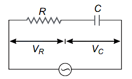
$A$ resistor and a capacitor are connected in series with an $AC$ source. If the potential drop across the capacitor is $5 \,V$ and that across the resistor is $12 \,V$, then the applied voltage is (in $\,V$)
A
$13$
B
$17$
C
$5$
D
$12$
Solution
(A) In an $RC$ series circuit, the voltage across the resistor $(V_R)$ and the voltage across the capacitor $(V_C)$ are out of phase by $90^{\circ}$.
Given: $V_R = 12 \,V$ and $V_C = 5 \,V$.
The total applied voltage $V$ is given by the phasor sum:
$V = \sqrt{V_R^2 + V_C^2}$
Substituting the values:
$V = \sqrt{(12)^2 + (5)^2}$
$V = \sqrt{144 + 25}$
$V = \sqrt{169}$
$V = 13 \,V$
Thus, the applied voltage is $13 \,V$.
Given: $V_R = 12 \,V$ and $V_C = 5 \,V$.
The total applied voltage $V$ is given by the phasor sum:
$V = \sqrt{V_R^2 + V_C^2}$
Substituting the values:
$V = \sqrt{(12)^2 + (5)^2}$
$V = \sqrt{144 + 25}$
$V = \sqrt{169}$
$V = 13 \,V$
Thus, the applied voltage is $13 \,V$.
0 likes
View Solution233
MediumMCQ
$A$ resistor of $500 \Omega$ and an inductor of $0.5 \ H$ are connected in series with an $AC$ source given by $V = 100 \sqrt{2} \sin(1000 t)$. The power factor of the combination is:
A
$0.6$
B
$\frac{1}{\sqrt{2}}$
C
$\frac{1}{\sqrt{3}}$
D
$0.5$
Solution
(B) Given voltage $V = 100 \sqrt{2} \sin(1000 t)$.
Comparing this with the standard equation $V = V_0 \sin(\omega t)$,we get angular frequency $\omega = 1000 \ rad/s$.
The inductive reactance is given by $X_L = \omega L = 1000 \times 0.5 = 500 \ \Omega$.
The resistance is $R = 500 \ \Omega$.
The impedance of the $RL$ series circuit is $Z = \sqrt{R^2 + X_L^2} = \sqrt{500^2 + 500^2} = 500 \sqrt{2} \ \Omega$.
The power factor is defined as $\cos \phi = \frac{R}{Z}$.
Substituting the values,$\cos \phi = \frac{500}{500 \sqrt{2}} = \frac{1}{\sqrt{2}}$.
0 likes
View Solution234
MediumMCQ
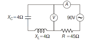
What will be the reading in the voltmeter and ammeter of the circuit shown?
A
$90 \, V, 2 \, A$
B
$0, 2 \, A$
C
$90 \, V, 1 \, A$
D
$0, 1 \, A$
Solution
(B) Given, $X_{L} = 4 \, \Omega$ and $X_{C} = 4 \, \Omega$.
In a series $LC$ circuit, the voltage across the inductor $(V_{L})$ and the capacitor $(V_{C})$ are $180^{\circ}$ out of phase.
Therefore, the net voltage across the series combination of the inductor and capacitor is $V_{\text{net}} = |V_{L} - V_{C}|$.
Since $X_{L} = X_{C}$, the magnitudes of the voltages are equal, i.e., $V_{L} = I X_{L}$ and $V_{C} = I X_{C}$.
Thus, $V_{\text{net}} = I(X_{L} - X_{C}) = I(4 - 4) = 0 \, V$.
The voltmeter is connected across this series $LC$ combination, so its reading is $0 \, V$.
The total impedance of the circuit is $Z = \sqrt{R^{2} + (X_{L} - X_{C})^{2}}$.
Substituting the values, $Z = \sqrt{45^{2} + (4 - 4)^{2}} = \sqrt{45^{2}} = 45 \, \Omega$.
The current in the circuit is $I = \frac{V}{Z} = \frac{90 \, V}{45 \, \Omega} = 2 \, A$.
Therefore, the voltmeter reading is $0 \, V$ and the ammeter reading is $2 \, A$.
0 likes
View Solution235
MediumMCQ
An electric bulb has a rated power of $50 \, W$ at $100 \, V$. If it is used on an $AC$ source of $200 \, V, 50 \, Hz$, a choke has to be used in series with it. This choke should have an inductance of (in $ \, H$)
A
$0.1$
B
$1$
C
$1.1$
D
$0.11$
Solution
(C) The resistance of the bulb is given by $R = \frac{V^2}{P} = \frac{100^2}{50} = 200 \, \Omega$.
For the bulb to operate at its rated power, the current $I$ must be $I = \frac{P}{V} = \frac{50}{100} = 0.5 \, A$.
When connected to a $200 \, V$ $AC$ source, the total impedance $Z$ of the circuit is $Z = \frac{V_{source}}{I} = \frac{200}{0.5} = 400 \, \Omega$.
The impedance of an $RL$ circuit is $Z = \sqrt{R^2 + X_L^2}$, where $X_L = 2\pi fL$.
Substituting the values: $400 = \sqrt{200^2 + X_L^2}$.
$160000 = 40000 + X_L^2 \implies X_L^2 = 120000$.
$X_L = \sqrt{120000} = 200\sqrt{3} \, \Omega$.
Since $X_L = 2\pi fL$, we have $200\sqrt{3} = 2 \times \pi \times 50 \times L$.
$L = \frac{200\sqrt{3}}{100\pi} = \frac{2\sqrt{3}}{\pi} \approx \frac{2 \times 1.732}{3.14} \approx 1.1 \, H$.
0 likes
View Solution236
EasyMCQ
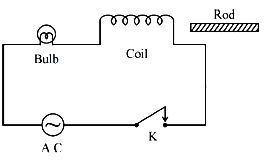
In the $A$.$C$. circuit shown,keeping switch $K$ closed,if an iron rod is inserted into the coil,the bulb in the circuit:
A
glows more brightly
B
glows less brightly
C
glows with the same brightness (as before the rod is inserted)
D
gets damaged
Solution
(B) When an iron rod is inserted into the coil,the permeability of the core increases,which significantly increases the self-inductance $(L)$ of the coil.
The inductive reactance of the circuit is given by $X_L = \omega L$.
As $L$ increases,the inductive reactance $X_L$ increases.
The total impedance of the circuit is $Z = \sqrt{R^2 + X_L^2}$,where $R$ is the resistance of the bulb.
Since $X_L$ increases,the total impedance $Z$ of the circuit increases.
According to Ohm's law for $A$.$C$. circuits,the current $I = V / Z$. As the impedance $Z$ increases,the current $I$ flowing through the circuit decreases.
The brightness of the bulb depends on the power dissipated,given by $P = I^2 R$. Since the current $I$ decreases,the power dissipated in the bulb decreases.
Therefore,the bulb glows less brightly.
0 likes
View Solution237
EasyMCQ
$A$ coil of inductive reactance $ \frac{1}{\sqrt{3}} \Omega $ and resistance $ 1 \Omega $ is connected to a $ 200 \ V, 50 \ Hz $ $AC$ supply. The time lag between maximum voltage and current is
A
$ \frac{1}{300} \ s $
B
$ \frac{1}{600} \ s $
C
$ \frac{1}{500} \ s $
D
$ \frac{1}{200} \ s $
Solution
(B) Given: Inductive reactance $ X_L = \omega L = \frac{1}{\sqrt{3}} \ \Omega $,Resistance $ R = 1 \ \Omega $,Frequency $ f = 50 \ Hz $.
In an $ RL $ circuit,the phase difference $ \phi $ between voltage and current is given by $ \tan \phi = \frac{X_L}{R} $.
Substituting the values,$ \tan \phi = \frac{1/\sqrt{3}}{1} = \frac{1}{\sqrt{3}} $.
Thus,$ \phi = 30^{\circ} = \frac{\pi}{6} \text{ radians} $.
The phase difference $ \phi $ is related to time lag $ t $ by the relation $ \phi = \omega t $.
Since $ \omega = 2\pi f = 2\pi \times 50 = 100\pi \ rad/s $.
Therefore,$ t = \frac{\phi}{\omega} = \frac{\pi/6}{100\pi} = \frac{1}{600} \ s $.
The time lag between maximum voltage and current is $ \frac{1}{600} \ s $.
0 likes
View Solution238
MediumMCQ
$A$ coil of inductive reactance $\frac{1}{\sqrt{3}} \Omega$ and a resistance $1 \Omega$ are connected in series to a $200 \ V, 50 \ Hz$ ac source. The time lag between voltage and current is
A
$\frac{1}{1200} \ s$
B
$\frac{1}{600} \ s$
C
$\frac{1}{400} \ s$
D
$\frac{1}{800} \ s$
Solution
(B) Given: Inductive reactance $X_L = \frac{1}{\sqrt{3}} \ \Omega$,Resistance $R = 1 \ \Omega$,Frequency $f = 50 \ Hz$.
In an $LR$ series circuit,the phase angle $\phi$ is given by $\tan \phi = \frac{X_L}{R}$.
$\tan \phi = \frac{1/\sqrt{3}}{1} = \frac{1}{\sqrt{3}}$.
Therefore,$\phi = 30^{\circ} = \frac{\pi}{6} \ \text{radians}$.
The phase difference $\phi$ is related to the time lag $\Delta t$ by the formula $\phi = \omega \Delta t$,where $\omega = 2\pi f$.
$\omega = 2 \times \pi \times 50 = 100\pi \ \text{rad/s}$.
Substituting the values: $\frac{\pi}{6} = 100\pi \times \Delta t$.
$\Delta t = \frac{\pi}{6 \times 100\pi} = \frac{1}{600} \ s$.
Thus,the time lag is $\frac{1}{600} \ s$.
0 likes
View Solution239
MediumMCQ
In a series $LCR$ circuit,the voltages across the capacitor,resistor,and inductor are in the ratio $2:3:6$. If the voltage of the ac source in the circuit is $240 \ V$,then the voltage across the inductor is (in $V$)
A
$240$
B
$144$
C
$96$
D
$288$
Solution
(D) Let the voltages across the capacitor,resistor,and inductor be $V_C = 2x$,$V_R = 3x$,and $V_L = 6x$ respectively.
In a series $LCR$ circuit,the total voltage $V$ is given by the relation $V = \sqrt{V_R^2 + (V_L - V_C)^2}$.
Given $V = 240 \ V$,we substitute the values:
$240 = \sqrt{(3x)^2 + (6x - 2x)^2}$
$240 = \sqrt{9x^2 + (4x)^2}$
$240 = \sqrt{9x^2 + 16x^2}$
$240 = \sqrt{25x^2}$
$240 = 5x$
$x = \frac{240}{5} = 48 \ V$.
The voltage across the inductor is $V_L = 6x = 6 \times 48 = 288 \ V$.
0 likes
View Solution240
DifficultMCQ
An inductor and a resistor are connected in series to an $AC$ source of voltage $V = 144 \sin \left(100 \pi t + \frac{\pi}{2}\right) \text{ V}$. If the current in the circuit is $I = 6 \sin \left(100 \pi t + \frac{\pi}{6}\right) \text{ A}$,then the resistance of the resistor is: (in $Omega$)
A
$24$
B
$36$
C
$12$
D
$18$
Solution
(C) Given voltage $V = 144 \sin \left(100 \pi t + \frac{\pi}{2}\right) \text{ V}$ and current $I = 6 \sin \left(100 \pi t + \frac{\pi}{6}\right) \text{ A}$.
Comparing with standard forms $V = V_0 \sin(\omega t + \phi_V)$ and $I = I_0 \sin(\omega t + \phi_I)$,we get $V_0 = 144 \text{ V}$,$I_0 = 6 \text{ A}$,and phase difference $\phi = \phi_V - \phi_I = \frac{\pi}{2} - \frac{\pi}{6} = \frac{\pi}{3} = 60^\circ$.
In an $LR$ series circuit,the phase angle $\phi$ is given by $\tan \phi = \frac{X_L}{R}$.
$\tan(60^\circ) = \frac{X_L}{R} \Rightarrow \sqrt{3} = \frac{X_L}{R} \Rightarrow X_L = \sqrt{3} R$.
The impedance $Z$ is given by $Z = \frac{V_0}{I_0} = \frac{144}{6} = 24 \ \Omega$.
Also,$Z = \sqrt{R^2 + X_L^2}$.
Substituting $X_L = \sqrt{3} R$,we get $24 = \sqrt{R^2 + (\sqrt{3} R)^2} = \sqrt{R^2 + 3R^2} = \sqrt{4R^2} = 2R$.
Therefore,$R = \frac{24}{2} = 12 \ \Omega$.
0 likes
View Solution241
MediumMCQ
The impedance of an $LR$ circuit with $L=\frac{60}{\pi} \text{ mH}$,$R=8 \Omega$ and frequency $f=50 \text{ Hz}$ is (in $Omega$)
A
$1.3$
B
$14.3$
C
$20$
D
$10$
Solution
(D) The impedance $Z$ of an $LR$ circuit is given by the formula: $Z = \sqrt{R^2 + X_L^2}$,where $X_L = \omega L = 2 \pi f L$.
Given: $R = 8 \Omega$,$L = \frac{60}{\pi} \text{ mH} = \frac{60}{\pi} \times 10^{-3} \text{ H}$,and $f = 50 \text{ Hz}$.
First,calculate the inductive reactance $X_L$:
$X_L = 2 \pi \times 50 \times \left( \frac{60}{\pi} \times 10^{-3} \right) = 100 \pi \times \frac{60}{\pi} \times 10^{-3} = 6000 \times 10^{-3} = 6 \Omega$.
Now,calculate the impedance $Z$:
$Z = \sqrt{R^2 + X_L^2} = \sqrt{8^2 + 6^2} = \sqrt{64 + 36} = \sqrt{100} = 10 \Omega$.
0 likes
View Solution242
EasyMCQ
In a series $L-C-R$ circuit,
A
the voltage leads the current if $X_L < X_C$
B
the voltage leads the current if $X_L > X_C$
C
the voltage and current are in phase
D
the current leads the voltage if $X_L > X_C$
Solution
(B) In a series $L-C-R$ circuit,the total voltage $V$ is given by the phasor sum of the voltages across the resistor,inductor,and capacitor.
The phase angle $\phi$ between the voltage and current is given by $\phi = \tan^{-1} \left( \frac{X_L - X_C}{R} \right)$.
If $X_L > X_C$,then $\phi$ is positive,which means the voltage leads the current.
If $X_L < X_C$,then $\phi$ is negative,which means the current leads the voltage.
Therefore,the voltage leads the current when $X_L > X_C$.
0 likes
View Solution243
MediumMCQ
When an inductor $L$ and a resistor $R$ in series are connected across a $12 \, V, 50 \, Hz$ supply, a current of $0.5 \, A$ flows in the circuit. The current differs in phase from the applied voltage by $\frac{\pi}{3}$ radian. Then the value of $R$ is (in $\Omega$)
A
$10$
B
$3$
C
$12$
D
$15$
Solution
(C) Given for the $LR$ series $AC$ circuit:
Voltage, $V_{rms} = 12 \, V$
Frequency, $f = 50 \, Hz$
Current, $I = 0.5 \, A$
Phase difference, $\phi = \frac{\pi}{3}$
First, calculate the total impedance $Z$ of the circuit using Ohm's law for $AC$ circuits:
$Z = \frac{V_{rms}}{I} = \frac{12}{0.5} = 24 \, \Omega$
The power factor of an $LR$ series circuit is given by:
$\cos \phi = \frac{R}{Z}$
Substituting the known values:
$\cos(\frac{\pi}{3}) = \frac{R}{24}$
Since $\cos(\frac{\pi}{3}) = 0.5$:
$0.5 = \frac{R}{24}$
$R = 24 \times 0.5 = 12 \, \Omega$
Therefore, the value of $R$ is $12 \, \Omega$.
0 likes
View Solution244
EasyMCQ
In the given circuit,the angular frequency of the voltage source is $70 \times 10^3 \text{ rad s}^{-1}$. The circuit effectively behaves like,
A
purely resistive circuit
B
series $RL$ circuit
C
series $RC$ circuit
D
series $LC$ circuit with $R$=$0$
Solution
(C) Given: $L = 10 \mu H = 10 \times 10^{-6} H$,$C = 1 \mu F = 10^{-6} F$,$R = 10 \Omega$,and angular frequency $\omega = 70 \times 10^3 \text{ rad s}^{-1}$.
First,calculate the inductive reactance $X_L = \omega L = (70 \times 10^3) \times (10 \times 10^{-6}) = 0.7 \Omega$.
Next,calculate the capacitive reactance $X_C = \frac{1}{\omega C} = \frac{1}{(70 \times 10^3) \times (10^{-6})} = \frac{1}{0.07} \approx 14.29 \Omega$.
Comparing the two,we find that $X_C > X_L$.
Since the capacitive reactance is significantly greater than the inductive reactance,the circuit behaves like a series $RC$ circuit.
0 likes
View Solution245
MediumMCQ
An inductor and a resistor are connected in series to an $AC$ source. The current in the circuit is $500 \,mA$, if the applied $AC$ voltage is $8 \sqrt{2} \,V$ at a frequency of $\frac{175}{\pi} \,Hz$, and the current in the circuit is $400 \,mA$, if the same $AC$ voltage at a frequency of $\frac{225}{\pi} \,Hz$ is applied. The values of the inductance and the resistance are respectively:
A
$60 \,mH, 71 \,\Omega$
B
$\sqrt{60} \,mH, 71 \,\Omega$
C
$\sqrt{60} \,mH, \sqrt{71} \,\Omega$
D
$60 \,mH, \sqrt{71} \,\Omega$
Solution
(D) For an $L-R$ circuit, the impedance $Z$ is given by $Z = \sqrt{R^2 + (L\omega)^2}$. The current is $I = V/Z$, so $R^2 + L^2\omega^2 = (V/I)^2$.
Case $1$: $I_1 = 0.5 \,A$, $f_1 = 175/\pi \,Hz$, $\omega_1 = 2\pi f_1 = 350 \,rad/s$, $V = 8\sqrt{2} \,V$.
$R^2 + L^2(350)^2 = (8\sqrt{2} / 0.5)^2 = (16\sqrt{2})^2 = 256 \times 2 = 512$.
Case $2$: $I_2 = 0.4 \,A$, $f_2 = 225/\pi \,Hz$, $\omega_2 = 2\pi f_2 = 450 \,rad/s$, $V = 8\sqrt{2} \,V$.
$R^2 + L^2(450)^2 = (8\sqrt{2} / 0.4)^2 = (20\sqrt{2})^2 = 400 \times 2 = 800$.
Subtracting the two equations: $L^2(450^2 - 350^2) = 800 - 512 = 288$.
$L^2(202500 - 122500) = 288 \Rightarrow L^2(80000) = 288$.
$L^2 = 288 / 80000 = 0.0036 \Rightarrow L = 0.06 \,H = 60 \,mH$.
Substituting $L$ into the first equation: $R^2 + (0.06 \times 350)^2 = 512$.
$R^2 + (21)^2 = 512 \Rightarrow R^2 + 441 = 512$.
$R^2 = 71 \Rightarrow R = \sqrt{71} \,\Omega$.
0 likes
View Solution246
MediumMCQ
An emf $E = 6 \cos(6000t) \ V$ is applied to an $L-R$ circuit of inductance $L = 4 \ mH$ and resistance $R = 7 \ \Omega$. The amplitude of the current in the circuit is . . . . . . (in $A$)
A
$0.24$
B
$0.14$
C
$0.54$
D
$0.84$
Solution
(A) Given: $E = 6 \cos(6000t) \ V$,$L = 4 \ mH = 4 \times 10^{-3} \ H$,$R = 7 \ \Omega$.
Comparing $E = E_0 \cos(\omega t)$ with the given equation,we get $E_0 = 6 \ V$ and $\omega = 6000 \ rad/s$.
The inductive reactance is $X_L = \omega L = 6000 \times 4 \times 10^{-3} = 24 \ \Omega$.
The impedance of the $L-R$ circuit is $Z = \sqrt{R^2 + X_L^2} = \sqrt{7^2 + 24^2} = \sqrt{49 + 576} = \sqrt{625} = 25 \ \Omega$.
The amplitude of the current $I_0$ is given by $I_0 = \frac{E_0}{Z} = \frac{6}{25} = 0.24 \ A$.
0 likes
View Solution247
EasyMCQ
An inductance of $0.2 \ H$ and resistance of $100 \ \Omega$ are connected in series to an $AC$ of $180 \ V$,$50 \ Hz$ supply. The $RMS$ current flowing in the circuit will be . . . . . . (Take $\pi^2$ as $10$). (in $A$)
A
$5.52$
B
$3.15$
C
$1.522$
D
$7.35$
Solution
(C) Given: Inductance $L = 0.2 \ H$,Resistance $R = 100 \ \Omega$,Voltage $V_{rms} = 180 \ V$,Frequency $f = 50 \ Hz$.
First,calculate the inductive reactance $X_L = 2 \pi f L$.
$X_L = 2 \times \pi \times 50 \times 0.2 = 20 \pi \ \Omega$.
Using $\pi^2 = 10$,we approximate $\pi \approx \sqrt{10} \approx 3.162$.
So,$X_L = 20 \times 3.162 = 63.24 \ \Omega$.
The impedance $Z$ of the $RL$ series circuit is $Z = \sqrt{R^2 + X_L^2}$.
$Z = \sqrt{100^2 + (63.24)^2} = \sqrt{10000 + 3999.3} = \sqrt{13999.3} \approx 118.32 \ \Omega$.
The $RMS$ current $I_{rms} = \frac{V_{rms}}{Z}$.
$I_{rms} = \frac{180}{118.32} \approx 1.5213 \ A$.
Rounding to three decimal places,we get $1.522 \ A$.
0 likes
View Solution248
EasyMCQ
In the figure,if $A$ and $B$ are identical bulbs,which bulb glows brighter?
A
$A$
B
$B$
C
Both with equal brightness
D
Both do not glow
Solution
(A) For bulb $A$ connected in series with an inductor $L = 100 \ mH$,the current is given by $I_1 = \frac{V_0}{X_L} = \frac{V_0}{\omega L} = \frac{V_0}{\omega \times 100 \times 10^{-3}} = \frac{10 V_0}{\omega}$.
For bulb $B$ connected in series with a capacitor $C = 10 \ pF$,the current is given by $I_2 = \frac{V_0}{X_C} = V_0 \omega C = V_0 \omega \times 10 \times 10^{-12}$.
Since the inductive reactance $X_L$ is typically much smaller than the capacitive reactance $X_C$ at standard frequencies,the current $I_1$ through bulb $A$ is significantly larger than the current $I_2$ through bulb $B$.
Therefore,$I_1 > I_2$,which implies that bulb $A$ will glow brighter.
0 likes
View Solution249
EasyMCQ
$A$ coil of inductance $0.1 H$ and resistance $110 \Omega$ is connected to a source of $110 V$ and $350 Hz$. The phase difference between the voltage maximum and the current maximum is
A
$\tan ^{-1}(1.5)$
B
$\tan ^{-1}(0.5)$
C
$\tan ^{-1}(1.73)$
D
$\tan ^{-1}(2)$
Solution
(D) The inductive reactance is given by $X_L = \omega L = 2 \pi f L$.
Substituting the given values: $X_L = 2 \times \pi \times 350 \times 0.1 = 70 \pi \approx 70 \times 3.14159 = 219.9 \Omega$.
In an $RL$ series circuit,the phase difference $\phi$ between the voltage and the current is given by $\tan \phi = \frac{X_L}{R}$.
Substituting the values: $\tan \phi = \frac{219.9}{110} \approx 1.999 \approx 2$.
Therefore,the phase difference is $\phi = \tan ^{-1}(2)$.
0 likes
View Solution250
EasyMCQ
$A$ circuit contains an inductance of $\frac{1}{6 \pi} \text{ H}$ and a resistance of $15 \text{ } \Omega$ in series. If an $AC$ voltage of $100 \text{ V}$ and $60 \text{ Hz}$ is applied to the circuit,then the current in the circuit and the phase difference between voltage and current are,respectively:
A
$4 \text{ A}$ and $\tan^{-1}\left(\frac{4}{5}\right)$
B
$5.3 \text{ A}$ and $\tan^{-1}\left(\frac{3}{4}\right)$
C
$4 \text{ A}$ and $\tan^{-1}\left(\frac{4}{3}\right)$
D
$5.3 \text{ A}$ and $\tan^{-1}\left(\frac{4}{3}\right)$
Solution
(C) Given: Inductance $L = \frac{1}{6 \pi} \text{ H}$,Resistance $R = 15 \text{ } \Omega$,Voltage $V = 100 \text{ V}$,Frequency $f = 60 \text{ Hz}$.
First,calculate the inductive reactance $X_L$:
$X_L = L \omega = L(2 \pi f) = \left(\frac{1}{6 \pi}\right) \times 2 \pi \times 60 = 20 \text{ } \Omega$.
Next,calculate the impedance $Z$ of the $LR$ series circuit:
$Z = \sqrt{R^2 + X_L^2} = \sqrt{15^2 + 20^2} = \sqrt{225 + 400} = \sqrt{625} = 25 \text{ } \Omega$.
The current $I$ in the circuit is:
$I = \frac{V}{Z} = \frac{100}{25} = 4 \text{ A}$.
The phase difference $\phi$ between voltage and current is given by:
$\tan \phi = \frac{X_L}{R} = \frac{20}{15} = \frac{4}{3}$.
Therefore,$\phi = \tan^{-1}\left(\frac{4}{3}\right)$.
0 likes
View SolutionAlternating Current — RL, RC and LC AC Circuits · Frequently Asked Questions
1Are these Alternating Current questions useful for JEE and NEET?
Yes. All questions in this section are mapped to JEE Main and NEET exam patterns. Previous year questions from JEE Main, NEET, GUJCET and state-level exams are included with full solutions.
2Can I switch to Hindi or Gujarati for these questions?
Yes. Use the language tabs in the hero section or the sidebar to view the same questions and solutions in English, Hindi or Gujarati.
3How do I generate a question paper from this subtopic?
Use the Vedclass Exam Paper Generator — select the chapter and subtopic, set difficulty, and generate Sets A, B, C, D automatically. First 3 chapters of every subject are free.
Vedclass Products
For Students
Vedclass Test Series
Mock tests in real JEE/NEET style with performance analysis. 5-day free trial.
Start Free TrialFor Teachers
Exam Paper Generator
Generate Set A/B/C/D papers from this chapter in 2 minutes. 3 chapters free.
Try FreeFor Institutes
Online Exam Module
Live online exams with unlimited students, 360° analytics & white-label branding.
See DemoFor Teachers & Institutes
Generate a Alternating Current Exam Paper in 2 Minutes
Select subtopic & difficulty — Sets A, B, C, D auto-generated with No Repeat logic.
First 3 chapters of every subject are free — no payment required.