
A English
RL, RC and LC AC Circuits Questions in English
Class 12 Physics · Alternating Current · RL, RC and LC AC Circuits
281+
Questions
English
Language
100%
With Solutions
Showing 46 of 281 questions in English
151
MediumMCQ
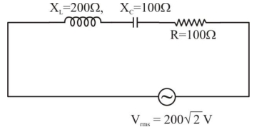
In the given circuit,the $rms$ value of current $(I_{rms})$ through the resistor $R$ is: $..........\,A$
A
$2$
B
$\frac{1}{2}$
C
$20$
D
$2 \sqrt{2}$
Solution
(A) The circuit is an $LCR$ series circuit with $R = 100\,\Omega$,$X_L = 200\,\Omega$,and $X_C = 100\,\Omega$.
The impedance $Z$ of the circuit is given by:
$Z = \sqrt{R^2 + (X_L - X_C)^2}$
$Z = \sqrt{100^2 + (200 - 100)^2}$
$Z = \sqrt{100^2 + 100^2} = \sqrt{2 \times 100^2} = 100 \sqrt{2}\,\Omega$
The $rms$ current $I_{rms}$ is given by:
$I_{rms} = \frac{V_{rms}}{Z}$
Given $V_{rms} = 200 \sqrt{2}\,V$,we have:
$I_{rms} = \frac{200 \sqrt{2}}{100 \sqrt{2}} = 2\,A$
0 likes
View Solution152
MediumMCQ
$A$ series $LCR$ circuit consists of $R = 80\,\Omega$,$X_{L} = 100\,\Omega$,and $X_{C} = 40\,\Omega$. The input voltage is $V = 2500 \cos(100\pi t)\,V$. The amplitude of current in the circuit is $................A$.
A
$24$
B
$23$
C
$25$
D
$22$
Solution
(C) The given parameters are $R = 80\,\Omega$,$X_{L} = 100\,\Omega$,and $X_{C} = 40\,\Omega$.
The peak voltage (amplitude) is $V_{0} = 2500\,V$.
The impedance $Z$ of the series $LCR$ circuit is given by $Z = \sqrt{R^2 + (X_{L} - X_{C})^2}$.
Substituting the values: $Z = \sqrt{80^2 + (100 - 40)^2} = \sqrt{80^2 + 60^2} = \sqrt{6400 + 3600} = \sqrt{10000} = 100\,\Omega$.
The amplitude of the current $I_{0}$ is given by $I_{0} = \frac{V_{0}}{Z}$.
$I_{0} = \frac{2500}{100} = 25\,A$.
0 likes
View Solution153
DifficultMCQ
$A$ series $L, R$ circuit connected with an ac source $E = (25 \sin 1000 t) \ V$ has a power factor of $\frac{1}{\sqrt{2}}$. If the source of emf is changed to $E = (20 \sin 2000 t) \ V$,the new power factor of the circuit will be:
A
$\frac{1}{\sqrt{2}}$
B
$\frac{1}{\sqrt{3}}$
C
$\frac{1}{\sqrt{5}}$
D
$\frac{1}{\sqrt{7}}$
Solution
(C) For a series $L, R$ circuit,the power factor is given by $\cos \phi = \frac{R}{Z} = \frac{R}{\sqrt{R^2 + X_L^2}}$,where $X_L = \omega L$.
Given the initial angular frequency $\omega_1 = 1000 \ rad/s$ and power factor $\cos \phi_1 = \frac{1}{\sqrt{2}}$.
Since $\cos \phi_1 = \frac{1}{\sqrt{2}}$,the phase angle $\phi_1 = 45^{\circ}$.
Thus,$\tan \phi_1 = \frac{X_{L1}}{R} = \frac{\omega_1 L}{R} = \tan 45^{\circ} = 1$.
This implies $R = \omega_1 L = 1000 L$.
When the source is changed to $E = (20 \sin 2000 t) \ V$,the new angular frequency is $\omega_2 = 2000 \ rad/s$.
The new inductive reactance is $X_{L2} = \omega_2 L = 2000 L = 2(\omega_1 L) = 2R$.
The new power factor is $\cos \phi_2 = \frac{R}{\sqrt{R^2 + X_{L2}^2}} = \frac{R}{\sqrt{R^2 + (2R)^2}} = \frac{R}{\sqrt{R^2 + 4R^2}} = \frac{R}{\sqrt{5R^2}} = \frac{1}{\sqrt{5}}$.
0 likes
View Solution154
DifficultMCQ
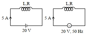
When a $DC$ voltage of $100 \, V$ is applied to an inductor, a $DC$ current of $5 \, A$ flows through it. When an $AC$ voltage of $200 \, V$ peak value is connected to the inductor, its inductive reactance is found to be $20\sqrt{3} \, \Omega$. The power dissipated in the circuit is . . . . . . $W$.
A
$238$
B
$240$
C
$245$
D
$250$
Solution
(D) For $DC$ voltage, the inductor acts as a pure resistor because $X_L = 0$ for $DC$.
$R = \frac{V}{I} = \frac{100 \, V}{5 \, A} = 20 \, \Omega$.
For $AC$ voltage, the circuit is an $LR$ series circuit.
Given $X_L = 20\sqrt{3} \, \Omega$ and $R = 20 \, \Omega$.
The impedance $Z$ is given by $Z = \sqrt{R^2 + X_L^2} = \sqrt{20^2 + (20\sqrt{3})^2} = \sqrt{400 + 1200} = \sqrt{1600} = 40 \, \Omega$.
The $RMS$ voltage is $V_{rms} = \frac{V_{peak}}{\sqrt{2}} = \frac{200}{\sqrt{2}} \, V$.
The $RMS$ current is $I_{rms} = \frac{V_{rms}}{Z} = \frac{200 / \sqrt{2}}{40} = \frac{5}{\sqrt{2}} \, A$.
The power dissipated in the circuit is $P = I_{rms}^2 R$.
$P = \left( \frac{5}{\sqrt{2}} \right)^2 \times 20 = \frac{25}{2} \times 20 = 250 \, W$.
0 likes
View Solution155
DifficultMCQ
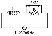
$A$ coil of negligible resistance is connected in series with a $90 \Omega$ resistor across a $120 \text{ V}, 60 \text{ Hz}$ supply. $A$ voltmeter reads $36 \text{ V}$ across the resistor. The inductance of the coil is: (in $\text{ H}$)
A
$0.76$
B
$2.86$
C
$0.286$
D
$0.91$
Solution
(A) Given: Resistance $R = 90 \Omega$, Supply voltage $V = 120 \text{ V}$, Frequency $f = 60 \text{ Hz}$, Voltage across resistor $V_R = 36 \text{ V}$.
The current in the series circuit is $I = \frac{V_R}{R} = \frac{36}{90} = 0.4 \text{ A}$.
The impedance of the circuit is $Z = \frac{V}{I} = \frac{120}{0.4} = 300 \Omega$.
We know $Z = \sqrt{R^2 + X_L^2}$, so $300 = \sqrt{90^2 + X_L^2}$.
Squaring both sides: $90000 = 8100 + X_L^2$.
$X_L^2 = 90000 - 8100 = 81900$.
$X_L = \sqrt{81900} \approx 286.18 \Omega$.
Since $X_L = 2 \pi f L$, we have $L = \frac{X_L}{2 \pi f} = \frac{286.18}{2 \times 3.14 \times 60} = \frac{286.18}{376.8} \approx 0.76 \text{ H}$.
0 likes
View Solution156
DifficultMCQ
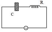
$A$ bulb and a capacitor are connected in series across an $AC$ supply. $A$ dielectric is then placed between the plates of the capacitor. The glow of the bulb:
A
increases
B
remains same
C
becomes zero
D
decreases
Solution
(A) The impedance of the $RC$ circuit is given by $Z = \sqrt{R^2 + X_C^2}$,where $X_C = \frac{1}{\omega C}$ is the capacitive reactance.
When a dielectric is placed between the plates of the capacitor,its capacitance $C$ increases $(C' = KC)$.
Since $X_C = \frac{1}{\omega C}$,an increase in $C$ leads to a decrease in capacitive reactance $(X_C \downarrow)$.
As $X_C$ decreases,the total impedance $Z = \sqrt{R^2 + X_C^2}$ of the circuit decreases $(Z \downarrow)$.
According to Ohm's law for $AC$ circuits,the current $I = \frac{V}{Z}$. Since $Z$ decreases,the current $I$ in the circuit increases.
Consequently,the power dissipated in the bulb $(P = I^2 R)$ increases,and the glow of the bulb increases.
0 likes
View Solution157
DifficultMCQ
When a coil is connected across a $20 \ V$ $DC$ supply,it draws a current of $5 \ A$. When it is connected across a $20 \ V, 50 \ Hz$ $AC$ supply,it draws a current of $4 \ A$. The self-inductance of the coil is .............. $mH$. (Take $\pi=3$)
A
$8$
B
$7$
C
$9$
D
$10$
Solution
(D) Case-$I$: $DC$ supply
For a $DC$ circuit,the inductor acts as a short circuit (resistance only).
$R = \frac{V}{I} = \frac{20 \ V}{5 \ A} = 4 \ \Omega$
Case-$II$: $AC$ supply
For an $AC$ circuit,the impedance $Z$ is given by $Z = \sqrt{R^2 + X_L^2}$.
$Z = \frac{V}{I} = \frac{20 \ V}{4 \ A} = 5 \ \Omega$
Since $Z^2 = R^2 + X_L^2$,we have $5^2 = 4^2 + X_L^2$.
$25 = 16 + X_L^2 \Rightarrow X_L^2 = 9 \Rightarrow X_L = 3 \ \Omega$
We know $X_L = 2 \pi f L$,where $f = 50 \ Hz$ and $\pi = 3$.
$3 = 2 \times 3 \times 50 \times L$
$3 = 300 \times L$
$L = \frac{3}{300} \ H = 0.01 \ H$
Converting to millihenry $(mH)$:
$L = 0.01 \times 1000 \ mH = 10 \ mH$
0 likes
View Solution158
DifficultMCQ
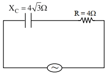
$A$ capacitor of reactance $4 \sqrt{3} \Omega$ and a resistor of resistance $4 \Omega$ are connected in series with an $AC$ source of peak value $8 \sqrt{2} \text{ V}$. The power dissipation in the circuit is . . . . . $\text{W}$.
A
$3$
B
$2$
C
$4$
D
$5$
Solution
(C) Given:
Reactance of capacitor $X_C = 4 \sqrt{3} \Omega$
Resistance $R = 4 \Omega$
Peak voltage $V_0 = 8 \sqrt{2} \text{ V}$
Step $1$: Calculate the impedance $Z$ of the $RC$ circuit.
$Z = \sqrt{R^2 + X_C^2}$
$Z = \sqrt{4^2 + (4 \sqrt{3})^2} = \sqrt{16 + 16 \times 3} = \sqrt{16 + 48} = \sqrt{64} = 8 \Omega$
Step $2$: Calculate the $RMS$ voltage $V_{\text{rms}}$.
$V_{\text{rms}} = \frac{V_0}{\sqrt{2}} = \frac{8 \sqrt{2}}{\sqrt{2}} = 8 \text{ V}$
Step $3$: Calculate the $RMS$ current $I_{\text{rms}}$.
$I_{\text{rms}} = \frac{V_{\text{rms}}}{Z} = \frac{8}{8} = 1 \text{ A}$
Step $4$: Calculate the power dissipation $P$.
Power is dissipated only in the resistor.
$P = I_{\text{rms}}^2 \times R = (1)^2 \times 4 = 4 \text{ W}$
0 likes
View Solution159
DifficultMCQ
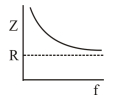
An $AC$ voltage source of variable angular frequency $\omega$ and fixed amplitude $V_0$ is connected in series with a capacitance $C$ and an electric bulb of resistance $R$ (inductance zero). When $\omega$ is increased,
A
the bulb glows dimmer
B
the bulb glows brighter
C
total impedance of the circuit is unchanged
D
total impedance of the circuit increases
Solution
(B) The impedance $Z$ of an $RC$ series circuit is given by $Z = \sqrt{R^2 + X_C^2}$,where $X_C = \frac{1}{\omega C}$ is the capacitive reactance.
Substituting $X_C$,we get $Z = \sqrt{R^2 + \left(\frac{1}{\omega C}\right)^2}$.
As the angular frequency $\omega$ increases,the capacitive reactance $X_C = \frac{1}{\omega C}$ decreases.
Since $Z = \sqrt{R^2 + X_C^2}$,a decrease in $X_C$ leads to a decrease in the total impedance $Z$ of the circuit.
The current in the circuit is given by $I = \frac{V_0}{Z}$. Since $V_0$ is constant and $Z$ decreases,the current $I$ increases.
The brightness of the bulb is proportional to the power dissipated,$P = I^2 R$. As the current $I$ increases,the power dissipated increases,and the bulb glows brighter.
0 likes
View Solution160
DifficultMCQ
$A$ series $R-C$ circuit is connected to an $AC$ voltage source. Consider two cases: $(A)$ when $C$ is without a dielectric medium and $(B)$ when $C$ is filled with a dielectric of constant $K = 4$. The current $I_R$ through the resistor and voltage $V_C$ across the capacitor are compared in the two cases. Which of the following is/are true?
A
$(B, C)$
B
$(B, D)$
C
$(A, D)$
D
$(C, D)$
Solution
(A) In a series $R-C$ circuit,the impedance is given by $Z = \sqrt{R^2 + X_C^2}$,where $X_C = \frac{1}{\omega C}$.
When a dielectric of constant $K = 4$ is inserted,the new capacitance becomes $C' = KC = 4C$.
Consequently,the new capacitive reactance becomes $X_C' = \frac{1}{\omega (4C)} = \frac{X_C}{4}$.
Since $X_C' < X_C$,the total impedance $Z' = \sqrt{R^2 + (X_C')^2}$ is less than $Z = \sqrt{R^2 + X_C^2}$.
The current in the circuit is $I = \frac{V}{Z}$. Since $Z' < Z$,the current in case $(B)$ is greater than in case $(A)$,so $I_R^B > I_R^A$ (Option $B$ is true).
The voltage across the capacitor is $V_C = I X_C = \frac{V}{\sqrt{R^2 + X_C^2}} X_C = \frac{V}{\sqrt{(R/X_C)^2 + 1}}$.
As $X_C$ decreases,the term $(R/X_C)^2$ increases,which makes the denominator $\sqrt{(R/X_C)^2 + 1}$ larger.
Therefore,$V_C$ decreases when $X_C$ decreases. Thus,$V_C^A > V_C^B$ (Option $C$ is true).
Hence,the correct statements are $(B)$ and $(C)$.
0 likes
View Solution161
DifficultMCQ
$A$ series $R-C$ combination is connected to an $AC$ voltage of angular frequency $\omega = 500 \ rad/s$. If the impedance of the $R-C$ circuit is $R\sqrt{1.25}$,the time constant (in $ms$) of the circuit is:
A
$5$
B
$6$
C
$4$
D
$8$
Solution
(C) Given: $\omega = 500 \ rad/s$.
The impedance $Z$ of a series $R-C$ circuit is given by $Z = \sqrt{R^2 + X_C^2}$,where $X_C = \frac{1}{\omega C}$.
Given $Z = R\sqrt{1.25}$,we have $Z^2 = 1.25R^2$.
Substituting into the impedance formula: $R^2 + X_C^2 = 1.25R^2$.
$X_C^2 = 0.25R^2$.
$X_C = 0.5R$.
Since $X_C = \frac{1}{\omega C}$,we have $\frac{1}{\omega C} = 0.5R$.
Rearranging for the time constant $\tau = RC$: $RC = \frac{1}{0.5\omega}$.
Substituting $\omega = 500 \ rad/s$: $\tau = \frac{1}{0.5 \times 500} = \frac{1}{250} = 0.004 \ s$.
Converting to milliseconds: $\tau = 0.004 \times 1000 \ ms = 4 \ ms$.
0 likes
View Solution162
AdvancedMCQ
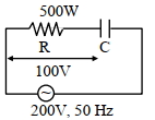
In a circuit,a metal filament lamp is connected in series with a capacitor of capacitance $C \mu F$ across a $200 V, 50 Hz$ supply. The power consumed by the lamp is $500 W$ while the voltage drop across it is $100 V$. Assume that there is no inductive load in the circuit. Take $rms$ values of the voltages. The magnitude of the phase-angle (in degrees) between the current and the supply voltage is $\varphi$.
Assume,$\pi \sqrt{3} \approx 5$.
$(1)$ The value of $C$ is . . . . . .
$(2)$ The value of $\varphi$ is
Give the answers of the questions $(1)$ and $(2)$:
Assume,$\pi \sqrt{3} \approx 5$.
$(1)$ The value of $C$ is . . . . . .
$(2)$ The value of $\varphi$ is
Give the answers of the questions $(1)$ and $(2)$:
A
$100, 60$
B
$100, 70$
C
$101, 60$
D
$102, 80$
Solution
(A) Given: Supply voltage $V = 200 V$,Frequency $f = 50 Hz$,Power $P = 500 W$,Voltage across lamp $V_R = 100 V$.
$1$. Since the circuit is an $RC$ series circuit,the supply voltage is $V = \sqrt{V_R^2 + V_C^2}$.
$200^2 = 100^2 + V_C^2 \Rightarrow V_C^2 = 40000 - 10000 = 30000$.
$V_C = 100\sqrt{3} V$.
$2$. The phase angle $\varphi$ is given by $\tan \varphi = \frac{V_C}{V_R} = \frac{100\sqrt{3}}{100} = \sqrt{3}$.
$\varphi = \tan^{-1}(\sqrt{3}) = 60^{\circ}$.
$3$. Power $P = V_R \cdot I \Rightarrow 500 = 100 \cdot I \Rightarrow I = 5 A$.
Also,$V_C = I \cdot X_C \Rightarrow 100\sqrt{3} = 5 \cdot X_C \Rightarrow X_C = 20\sqrt{3} \Omega$.
$4$. $X_C = \frac{1}{2\pi f C} \Rightarrow 20\sqrt{3} = \frac{1}{2 \cdot \pi \cdot 50 \cdot C \cdot 10^{-6}}$.
$C = \frac{1}{20\sqrt{3} \cdot 100 \cdot \pi} \cdot 10^6 = \frac{10^6}{2000 \cdot \pi \sqrt{3}} = \frac{1000}{2 \cdot 5} = 100 \mu F$.
Thus,$C = 100 \mu F$ and $\varphi = 60^{\circ}$.
0 likes
View Solution163
MediumMCQ
An inductor of self-inductance $1 \ H$ is connected in series with a resistor of $100 \pi \ \Omega$ and an $AC$ supply of $100 \pi \ V$,$50 \ Hz$. The maximum current flowing in the circuit is . . . . . . $A$.
A
$1$
B
$2$
C
$3$
D
$4$
Solution
(A) Given: Self-inductance $L = 1 \ H$,Resistance $R = 100 \pi \ \Omega$,Voltage $V_{rms} = 100 \pi \ V$,Frequency $f = 50 \ Hz$.
First,calculate the inductive reactance $X_L = \omega L = 2 \pi f L = 2 \pi \times 50 \times 1 = 100 \pi \ \Omega$.
The impedance of the $LR$ series circuit is $Z = \sqrt{R^2 + X_L^2} = \sqrt{(100 \pi)^2 + (100 \pi)^2} = \sqrt{2 \times (100 \pi)^2} = 100 \pi \sqrt{2} \ \Omega$.
The $RMS$ current is $I_{rms} = \frac{V_{rms}}{Z} = \frac{100 \pi}{100 \pi \sqrt{2}} = \frac{1}{\sqrt{2}} \ A$.
The maximum current $I_{max}$ is given by $I_{max} = I_{rms} \sqrt{2} = \frac{1}{\sqrt{2}} \times \sqrt{2} = 1 \ A$.
0 likes
View Solution164
DifficultMCQ
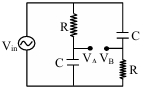
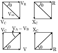
For the $AC$ circuit shown in the figure,$R = 100 \ k\Omega$ and $C = 100 \ pF$. The phase difference between $V_{\text{in}}$ and $(V_B - V_A)$ is $90^{\circ}$. The input signal frequency is $10^x \ rad/sec$,where $x$ is . . . . . . .
A
$7$
B
$5$
C
$2$
D
$9$
Solution
(B) Let the input voltage be $V_{\text{in}}$. The circuit consists of two potential dividers in parallel.
For the left branch,the voltage at point $A$ with respect to the bottom node is $V_A = V_{\text{in}} \cdot \frac{-jX_C}{R - jX_C}$.
For the right branch,the voltage at point $B$ with respect to the bottom node is $V_B = V_{\text{in}} \cdot \frac{R}{R - jX_C}$.
Thus,the potential difference $(V_B - V_A)$ is given by:
$V_B - V_A = V_{\text{in}} \cdot \frac{R + jX_C}{R - jX_C}$.
Let $Z = R - jX_C$. Then $V_B - V_A = V_{\text{in}} \cdot \frac{R + jX_C}{R - jX_C}$.
The phase of $(V_B - V_A)$ relative to $V_{\text{in}}$ is the phase of $\frac{R + jX_C}{R - jX_C}$.
Let $\tan \theta = \frac{X_C}{R}$. Then the phase of $(R + jX_C)$ is $\theta$ and the phase of $(R - jX_C)$ is $-\theta$.
The phase of the ratio is $\theta - (-\theta) = 2\theta$.
Given the phase difference is $90^{\circ}$,we have $2\theta = 90^{\circ}$,so $\theta = 45^{\circ}$.
Therefore,$\tan 45^{\circ} = \frac{X_C}{R} \implies 1 = \frac{1}{\omega RC} \implies \omega = \frac{1}{RC}$.
Substituting the values: $R = 10^5 \ \Omega$,$C = 100 \times 10^{-12} \ F = 10^{-10} \ F$.
$\omega = \frac{1}{10^5 \times 10^{-10}} = \frac{1}{10^{-5}} = 10^5 \ rad/sec$.
Comparing with $10^x$,we get $x = 5$.
0 likes
View Solution165
EasyMCQ
$A$ bulb and a capacitor are connected in series to a source of alternating current. If its frequency is increased,while keeping the voltage of the source constant,then
A
Bulb will give more intense light
B
Bulb will give less intense light
C
Bulb will give light of same intensity as before
D
Bulb will stop radiating light
Solution
(A) The circuit consists of a bulb (resistor $R$) and a capacitor $(C)$ connected in series,forming an $R-C$ circuit.
The impedance of an $R-C$ circuit is given by $Z = \sqrt{R^2 + X_C^2}$,where $X_C = \frac{1}{2\pi fC}$ is the capacitive reactance.
When the frequency $f$ of the $AC$ source is increased,the capacitive reactance $X_C = \frac{1}{2\pi fC}$ decreases.
Since $Z = \sqrt{R^2 + X_C^2}$,a decrease in $X_C$ leads to a decrease in the total impedance $Z$ of the circuit.
According to Ohm's law for $AC$ circuits,the current $i$ is given by $i = \frac{V}{Z}$. Since the source voltage $V$ is constant and $Z$ decreases,the current $i$ flowing through the circuit increases.
The brightness of the bulb is proportional to the power dissipated,$P = i^2R$. As the current $i$ increases,the power dissipated by the bulb increases,and thus the bulb will give more intense light.
0 likes
View Solution166
DifficultMCQ
$A$ student connects a long air-cored coil of manganin wire to a $100 \ V$ $DC$ supply and records a current of $25 \ A$. When the same coil is connected across a $100 \ V, 50 \ Hz$ $AC$ supply,the current reduces to $20 \ A$. The reactance of the coil is $...... \Omega$.
A
$4$
B
$3$
C
$5$
D
$0$
Solution
(B) For $DC$ supply,the coil acts as a pure resistor $R$. Given $V = 100 \ V$ and $I = 25 \ A$,the resistance is $R = \frac{V}{I} = \frac{100}{25} = 4 \ \Omega$.
For $AC$ supply,the coil acts as an $LR$ circuit with impedance $Z$. Given $V = 100 \ V$ and $I = 20 \ A$,the impedance is $Z = \frac{V}{I} = \frac{100}{20} = 5 \ \Omega$.
The impedance $Z$ is related to resistance $R$ and inductive reactance $X_L$ by the formula $Z^2 = R^2 + X_L^2$.
Substituting the values,$5^2 = 4^2 + X_L^2$.
$25 = 16 + X_L^2 \Rightarrow X_L^2 = 25 - 16 = 9$.
Therefore,the reactance $X_L = \sqrt{9} = 3 \ \Omega$.
0 likes
View Solution167
MediumMCQ
An alternating e.m.f. having voltage $V = V_0 \sin \omega t$ is applied to a series $L-C-R$ circuit. Given: $|X_L - X_C| = R$. The r.m.s. value of potential difference across the capacitor will be:
A
$V_0 R \omega C$
B
$\frac{V_0}{R \omega C}$
C
$\frac{V_0}{2 R \omega C}$
D
$\frac{V_0}{\sqrt{2} R \omega C}$
Solution
(C) The impedance of the series $L-C-R$ circuit is given by $Z = \sqrt{R^2 + (X_L - X_C)^2}$.
Given $|X_L - X_C| = R$,we substitute this into the impedance formula:
$Z = \sqrt{R^2 + R^2} = \sqrt{2R^2} = R\sqrt{2}$.
The peak current in the circuit is $I_0 = \frac{V_0}{Z} = \frac{V_0}{R\sqrt{2}}$.
The potential difference across the capacitor is $V_C = I_0 X_C$.
The r.m.s. value of the potential difference across the capacitor is $V_{C,rms} = I_{rms} X_C$.
Since $I_{rms} = \frac{I_0}{\sqrt{2}} = \frac{V_0}{R\sqrt{2} \cdot \sqrt{2}} = \frac{V_0}{2R}$,we have:
$V_{C,rms} = \frac{V_0}{2R} \cdot \frac{1}{\omega C} = \frac{V_0}{2R\omega C}$.
0 likes
View Solution168
EasyMCQ
An a.c. source of frequency $f$ is connected to a circuit containing an inductance $L$ and resistance $R$ in series. The impedance of this circuit is
A
$\sqrt{R^2+2 \pi fL^2}$
B
$\sqrt{R^2+L^2}$
C
$R+2 \pi fL$
D
$\sqrt{R^2+4 \pi^2 f^2 L^2}$
Solution
(D) In an $LR$ series circuit,the impedance $Z$ is given by the formula $Z = \sqrt{R^2 + X_L^2}$.
Here,$R$ is the resistance and $X_L$ is the inductive reactance.
The inductive reactance $X_L$ is defined as $X_L = \omega L$,where $\omega = 2 \pi f$.
Substituting the value of $\omega$,we get $X_L = 2 \pi f L$.
Now,substituting $X_L$ into the impedance formula:
$Z = \sqrt{R^2 + (2 \pi f L)^2}$
$Z = \sqrt{R^2 + 4 \pi^2 f^2 L^2}$.
Thus,the correct option is $D$.
0 likes
View Solution169
EasyMCQ
In an $LR$ circuit,the value of $L$ is $(\frac{0.3}{\pi}) \ H$ and the value of $R$ is $40 \ \Omega$. If an alternating e.m.f. of $230 \ V$ at $50 \ Hz$ is connected to the circuit,what are the impedance and the current in the circuit,respectively?
A
$12.5 \ \Omega, 9.2 \ A$
B
$46.4 \ \Omega, 6.4 \ A$
C
$23.2 \ \Omega, 5 \ A$
D
$50 \ \Omega, 4.6 \ A$
Solution
(D) Given: Inductance $L = \frac{0.3}{\pi} \ H$,Resistance $R = 40 \ \Omega$,Voltage $V = 230 \ V$,Frequency $f = 50 \ Hz$.
First,calculate the inductive reactance $X_L = 2\pi f L$.
$X_L = 2 \times \pi \times 50 \times \frac{0.3}{\pi} = 100 \times 0.3 = 30 \ \Omega$.
The impedance $Z$ of the $LR$ circuit is given by $Z = \sqrt{R^2 + X_L^2}$.
$Z = \sqrt{40^2 + 30^2} = \sqrt{1600 + 900} = \sqrt{2500} = 50 \ \Omega$.
The current $I$ in the circuit is given by $I = \frac{V}{Z}$.
$I = \frac{230}{50} = 4.6 \ A$.
Thus,the impedance is $50 \ \Omega$ and the current is $4.6 \ A$.
0 likes
View Solution170
MediumMCQ
An inductor of $\left(\frac{100}{\pi}\right) mH$,a capacitor of capacitance $\left(\frac{10^{-3}}{2 \pi}\right) F$,and a resistor of $10 \Omega$ are connected in series with an $AC$ voltage source of $110 \text{ V}, 50 \text{ Hz}$. The tangent of the phase angle $\phi$ between the voltage and the current is:
A
$4$
B
$3$
C
$2$
D
$1$
Solution
(D) Given: Inductance $L = \frac{100}{\pi} \text{ mH} = \frac{0.1}{\pi} \text{ H}$,Capacitance $C = \frac{10^{-3}}{2\pi} \text{ F}$,Resistance $R = 10 \Omega$,Frequency $f = 50 \text{ Hz}$.
First,calculate the inductive reactance $X_L = 2\pi f L = 2\pi \times 50 \times \frac{0.1}{\pi} = 100 \times 0.1 = 10 \Omega$.
Next,calculate the capacitive reactance $X_C = \frac{1}{2\pi f C} = \frac{1}{2\pi \times 50 \times \frac{10^{-3}}{2\pi}} = \frac{1}{50 \times 10^{-3}} = \frac{1000}{50} = 20 \Omega$.
The tangent of the phase angle $\phi$ is given by $\tan \phi = \frac{X_L - X_C}{R}$.
Substituting the values: $\tan \phi = \frac{10 - 20}{10} = \frac{-10}{10} = -1$.
The magnitude of the tangent of the phase angle is $|\tan \phi| = 1$.
0 likes
View Solution171
MediumMCQ
An inductance coil has a resistance of $80 \Omega$. When an $AC$ signal of frequency $480 \text{ Hz}$ is applied to the coil,the voltage leads the current by $45^{\circ}$. The inductance of the coil in henry is $\left[\sin 45^{\circ}=\cos 45^{\circ}=1 / \sqrt{2}\right]$
A
$\frac{1}{24 \pi}$
B
$\frac{\pi}{20}$
C
$\frac{\pi}{40}$
D
$\frac{1}{12 \pi}$
Solution
(D) The phase angle $\phi$ between voltage and current in an $RL$ circuit is given by $\tan \phi = \frac{X_L}{R}$.
Given $\phi = 45^{\circ}$,$R = 80 \Omega$,and $f = 480 \text{ Hz}$.
Since $\tan 45^{\circ} = 1$,we have $1 = \frac{X_L}{R}$,which implies $X_L = R$.
Substituting $X_L = 2 \pi f L$,we get $2 \pi f L = R$.
Solving for $L$: $L = \frac{R}{2 \pi f}$.
Substituting the values: $L = \frac{80}{2 \pi \times 480} = \frac{80}{960 \pi} = \frac{1}{12 \pi} \text{ H}$.
0 likes
View Solution172
MediumMCQ
When $80 \ V$ $d.c.$ is applied across a solenoid,a current of $0.8 \ A$ flows in it. When $80 \ V$ $a.c.$ is applied across the same solenoid,the current becomes $0.4 \ A$. If the frequency of $a.c.$ source is $50 \ Hz$,the impedance and inductance of the solenoid are nearly:
A
$200 \ \Omega, 0.55 \ H$
B
$100 \ \Omega, 0.8 \ H$
C
$300 \ \Omega, 1.2 \ H$
D
$200 \ \Omega, 1.5 \ H$
Solution
(A) When $80 \ V$ $d.c.$ is applied,the solenoid acts as a pure resistor because the frequency of $d.c.$ is zero,so inductive reactance $X_L = 2 \pi fL = 0$.
Resistance $R = \frac{V}{I_{dc}} = \frac{80 \ V}{0.8 \ A} = 100 \ \Omega$.
When $80 \ V$ $a.c.$ is applied,the impedance $Z$ is given by $Z = \frac{V}{I_{ac}} = \frac{80 \ V}{0.4 \ A} = 200 \ \Omega$.
The impedance of an $RL$ circuit is $Z = \sqrt{R^2 + X_L^2}$.
Substituting the values: $200 = \sqrt{100^2 + X_L^2}$.
$40000 = 10000 + X_L^2 \Rightarrow X_L^2 = 30000$.
$X_L = \sqrt{30000} \approx 173.2 \ \Omega$.
Since $X_L = 2 \pi fL$,we have $L = \frac{X_L}{2 \pi f} = \frac{173.2}{2 \times 3.14 \times 50} = \frac{173.2}{314} \approx 0.55 \ H$.
Thus,the impedance is $200 \ \Omega$ and the inductance is $0.55 \ H$.
0 likes
View Solution173
EasyMCQ
For the series $LCR$ circuit,$R = \frac{X_L}{2} = 2 X_C$. The impedance of the circuit and the phase difference between $V$ and $I$ will be
A
$\frac{\sqrt{5}}{2} R, \tan^{-1}\left(\frac{1}{2}\right)$
B
$\frac{\sqrt{13}}{2} R, \tan^{-1}\left(\frac{3}{2}\right)$
C
$\sqrt{5} R, \tan^{-1}(1)$
D
$\sqrt{13} R, \tan^{-1}(2)$
Solution
(B) The impedance $Z$ of a series $LCR$ circuit is given by $Z = \sqrt{R^2 + (X_L - X_C)^2}$.
Given $R = \frac{X_L}{2}$,we have $X_L = 2R$.
Given $R = 2X_C$,we have $X_C = \frac{R}{2}$.
Substituting these values into the impedance formula:
$Z = \sqrt{R^2 + (2R - \frac{R}{2})^2} = \sqrt{R^2 + (\frac{3R}{2})^2} = \sqrt{R^2 + \frac{9R^2}{4}} = \sqrt{\frac{13R^2}{4}} = \frac{\sqrt{13}}{2} R$.
The phase difference $\phi$ is given by $\tan \phi = \frac{X_L - X_C}{R}$.
Substituting the values: $\tan \phi = \frac{2R - R/2}{R} = \frac{3R/2}{R} = \frac{3}{2}$.
Therefore,$\phi = \tan^{-1}(\frac{3}{2})$.
0 likes
View Solution174
MediumMCQ
An a.c. voltage source $V=V_0 \sin \omega t$ is connected across resistance $R$ and capacitance $C$ in series. It is given that $R=\frac{1}{\omega C}$ and the peak current is $I_0$. If the angular frequency of the voltage source is changed to $\frac{\omega}{\sqrt{3}}$,then the new peak current in the circuit is
A
$\frac{I_0}{2}$
B
$\frac{I_0}{\sqrt{2}}$
C
$\sqrt{2} I_0$
D
$\sqrt{3} I_0$
Solution
(B) Given: $R = X_C = \frac{1}{\omega C}$.
Initial impedance $Z = \sqrt{R^2 + X_C^2} = \sqrt{R^2 + R^2} = \sqrt{2} R$.
Initial peak current $I_0 = \frac{V_0}{Z} = \frac{V_0}{\sqrt{2} R}$,which implies $\frac{V_0}{R} = \sqrt{2} I_0$.
When angular frequency $\omega' = \frac{\omega}{\sqrt{3}}$,the new capacitive reactance $X_C' = \frac{1}{\omega' C} = \frac{1}{(\omega / \sqrt{3}) C} = \sqrt{3} \left(\frac{1}{\omega C}\right) = \sqrt{3} R$.
New impedance $Z' = \sqrt{R^2 + (X_C')^2} = \sqrt{R^2 + (\sqrt{3} R)^2} = \sqrt{R^2 + 3R^2} = \sqrt{4R^2} = 2R$.
New peak current $I_0' = \frac{V_0}{Z'} = \frac{V_0}{2R} = \frac{1}{2} \left(\frac{V_0}{R}\right) = \frac{1}{2} (\sqrt{2} I_0) = \frac{I_0}{\sqrt{2}}$.
0 likes
View Solution175
DifficultMCQ
With an alternating voltage source of frequency $f$,an inductor $L$,a capacitor $C$,and a resistor $R$ are connected in series. The voltage leads the current by $45^{\circ}$. The value of $L$ is $(\tan 45^{\circ} = 1)$.
A
$\left(\frac{1+2 \pi fCR}{4 \pi^2 f^2 C}\right)$
B
$\left(\frac{1-2 \pi fCR}{4 \pi^2 f^2 C}\right)$
C
$\left(\frac{4 \pi^2 f^2 C}{1+2 \pi fCR}\right)$
D
$\left(\frac{4 \pi^2 f^2 C}{1-2 \pi fCR}\right)$
Solution
(A) The phase difference $\phi$ between the voltage and current in an $LCR$ series circuit is given by: $\tan \phi = \frac{X_L - X_C}{R}$.
Given $\phi = 45^{\circ}$,so $\tan 45^{\circ} = 1$.
Thus,$\frac{\omega L - \frac{1}{\omega C}}{R} = 1$.
$\omega L - \frac{1}{\omega C} = R$.
$\omega L = R + \frac{1}{\omega C} = \frac{R \omega C + 1}{\omega C}$.
Since $\omega = 2 \pi f$,we have $L = \frac{R \omega C + 1}{\omega^2 C} = \frac{R(2 \pi f)C + 1}{(2 \pi f)^2 C}$.
$L = \frac{1 + 2 \pi fCR}{4 \pi^2 f^2 C}$.
0 likes
View Solution176
DifficultMCQ
When $100 \ V$ $d.c.$ is applied across a solenoid,a current of $1 \ A$ flows in it. When $100 \ V$ $a.c.$ is applied across it,the current drops to $0.5 \ A$. If the frequency is $50 \ Hz$,the impedance and inductance are:
A
$200 \ \Omega, \frac{\sqrt{3}}{\pi} \ H$
B
$100 \ \Omega, \sqrt{3} \ H$
C
$200 \ \Omega, 1 \ H$
D
$100 \ \Omega, 1 \ H$
Solution
(A) For $d.c.$ supply,the inductor acts as a pure resistor:
$R = \frac{V}{I} = \frac{100 \ V}{1 \ A} = 100 \ \Omega$.
For $a.c.$ supply,the impedance $Z$ is given by:
$Z = \frac{V}{I} = \frac{100 \ V}{0.5 \ A} = 200 \ \Omega$.
The impedance of an $LR$ circuit is $Z = \sqrt{R^2 + X_L^2}$,where $X_L = 2 \pi f L$.
Substituting the values: $200 = \sqrt{100^2 + X_L^2}$.
Squaring both sides: $40000 = 10000 + X_L^2 \Rightarrow X_L^2 = 30000$.
$X_L = \sqrt{30000} = 100\sqrt{3} \ \Omega$.
Since $X_L = 2 \pi f L$,we have $100\sqrt{3} = 2 \pi (50) L$.
$100\sqrt{3} = 100 \pi L \Rightarrow L = \frac{\sqrt{3}}{\pi} \ H$.
0 likes
View Solution177
MediumMCQ
When a coil is connected to a $d.c.$ source of $e.m.f.$ $12 \ V$,the current of $4 \ A$ flows in it. If the same coil is connected to a $12 \ V, 50 \ Hz$ $a.c.$ source,the current flowing in it is $2.4 \ A$. The self-inductance of the coil will be:
A
$48 \ H$
B
$12 \ H$
C
$\frac{4}{\pi} \times 10^{-2} \ H$
D
$\frac{8}{\pi} \times 10^{-2} \ H$
Solution
(C) For a $d.c.$ source,the inductor acts as a simple resistor because the frequency is zero. Thus,the resistance $R$ is given by $R = \frac{V}{I} = \frac{12 \ V}{4 \ A} = 3 \ \Omega$.
For an $a.c.$ source,the impedance $Z$ is given by $Z = \frac{V}{I} = \frac{12 \ V}{2.4 \ A} = 5 \ \Omega$.
The impedance of an $RL$ circuit is $Z = \sqrt{R^2 + X_L^2}$,where $X_L$ is the inductive reactance.
Squaring both sides,$Z^2 = R^2 + X_L^2$,so $X_L^2 = Z^2 - R^2 = 5^2 - 3^2 = 25 - 9 = 16$.
Thus,$X_L = 4 \ \Omega$.
Since $X_L = 2 \pi f L$,we have $L = \frac{X_L}{2 \pi f} = \frac{4}{2 \pi \times 50} = \frac{4}{100 \pi} = \frac{4}{\pi} \times 10^{-2} \ H$.
0 likes
View Solution178
EasyMCQ
$A$ light bulb connected in series with a capacitor and an $A.C.$ source is glowing with a certain brightness. On reducing the capacitance of the capacitor and the frequency of the source,the brightness of the lamp (respectively):
A
is reduced,is increased
B
is reduced,is reduced
C
is increased,is reduced
D
is increased,is increased
Solution
(B) The capacitive reactance of a capacitor is given by the formula $X_{C} = \frac{1}{2 \pi f C}$.
Here,$f$ is the frequency of the $A.C.$ source and $C$ is the capacitance.
When the capacitance $C$ is reduced,the capacitive reactance $X_{C}$ increases.
Similarly,when the frequency $f$ is reduced,the capacitive reactance $X_{C}$ increases.
Since the bulb is in series with the capacitor,the total impedance $Z$ of the circuit is given by $Z = \sqrt{R^2 + X_{C}^2}$.
As $X_{C}$ increases in both cases,the total impedance $Z$ of the circuit increases.
According to Ohm's law for $A.C.$ circuits,the current $I = \frac{V}{Z}$.
Since the impedance $Z$ increases,the current $I$ flowing through the bulb decreases.
The brightness of the bulb depends on the power dissipated,$P = I^2 R$.
As the current $I$ decreases,the power dissipated and the brightness of the lamp decrease in both cases.
0 likes
View Solution179
EasyMCQ
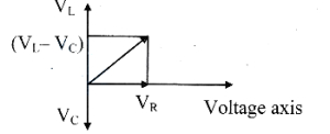
In an $LCR$ series circuit,if $V$ is the effective value of the applied voltage,$V_R$ is the voltage across $R$,and $V_L$ and $V_C$ are the effective voltages across $L$ and $C$ respectively,then:
A
$V=V_{R}+V_{L}+V_{C}$
B
$V^2=V_{R}^2+V_{L}^2+V_{C}^2$
C
$V^2=V_{R}^2+\left(V_{L}-V_{C}\right)^2$
D
$V^2=V_{L}^2+\left(V_{R}-V_{C}\right)^2$
Solution
(C) In an $LCR$ series circuit,the current $I$ is the same through all components. The voltage across the resistor $V_R$ is in phase with the current. The voltage across the inductor $V_L$ leads the current by $90^\circ$,and the voltage across the capacitor $V_C$ lags behind the current by $90^\circ$.
Thus,$V_L$ and $V_C$ are in opposite directions. The net reactive voltage is $(V_L - V_C)$.
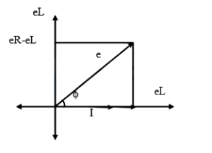
Using the phasor diagram,the resultant voltage $V$ is the vector sum of $V_R$ and $(V_L - V_C)$,which are perpendicular to each other.
Applying the Pythagorean theorem: $V^2 = V_R^2 + (V_L - V_C)^2$.
Thus,$V_L$ and $V_C$ are in opposite directions. The net reactive voltage is $(V_L - V_C)$.
Using the phasor diagram,the resultant voltage $V$ is the vector sum of $V_R$ and $(V_L - V_C)$,which are perpendicular to each other.
Applying the Pythagorean theorem: $V^2 = V_R^2 + (V_L - V_C)^2$.
0 likes
View Solution180
MediumMCQ
An e.m.f. $E=4 \cos (1000 t)$ volt is applied to an $LR$ circuit of inductance $3 \ mH$ and resistance $4 \ \Omega$. The maximum current in the circuit is
A
$\frac{4}{\sqrt{7}} \ A$
B
$1.0 \ A$
C
$\frac{4}{7} \ A$
D
$0.8 \ A$
Solution
(D) For an $LR$ circuit,the impedance $Z$ is given by $Z = \sqrt{R^2 + (\omega L)^2}$.
Comparing the given equation $E = 4 \cos(1000 t)$ with the standard equation $E = E_0 \cos(\omega t)$,we get $E_0 = 4 \ V$ and $\omega = 1000 \ rad/s$.
Given $L = 3 \ mH = 3 \times 10^{-3} \ H$ and $R = 4 \ \Omega$.
The inductive reactance is $X_L = \omega L = 1000 \times 3 \times 10^{-3} = 3 \ \Omega$.
Now,calculate the impedance $Z = \sqrt{R^2 + X_L^2} = \sqrt{4^2 + 3^2} = \sqrt{16 + 9} = \sqrt{25} = 5 \ \Omega$.
The maximum current $I_0$ is given by $I_0 = \frac{E_0}{Z} = \frac{4}{5} = 0.8 \ A$.
0 likes
View Solution181
MediumMCQ
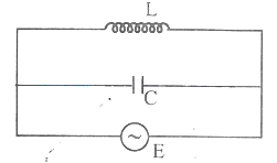
In the circuit given below,the current through the inductor is $0.6 \,A$ and through the capacitor is $0.9 \,A$. The current drawn from the a.c. source is (in $\,A$)
A
$1.5$
B
$0.9$
C
$0.6$
D
$0.3$
Solution
(D) In a parallel $LC$ circuit,the current through the inductor $(I_L)$ lags the voltage by $90^{\circ}$,and the current through the capacitor $(I_C)$ leads the voltage by $90^{\circ}$.
Thus,the currents $I_L$ and $I_C$ are $180^{\circ}$ out of phase.
The total current $I$ drawn from the source is the magnitude of the difference between the two currents:
$I = |I_C - I_L|$
Given $I_L = 0.6 \,A$ and $I_C = 0.9 \,A$.
$I = |0.9 \,A - 0.6 \,A| = 0.3 \,A$.
Thus,the currents $I_L$ and $I_C$ are $180^{\circ}$ out of phase.
The total current $I$ drawn from the source is the magnitude of the difference between the two currents:
$I = |I_C - I_L|$
Given $I_L = 0.6 \,A$ and $I_C = 0.9 \,A$.
$I = |0.9 \,A - 0.6 \,A| = 0.3 \,A$.
0 likes
View Solution182
EasyMCQ
In a series $LCR$ circuit,the voltages across the inductance and the capacitance are not
A
out of phase with the voltage across the resistance by $90^{\circ}$.
B
equal in magnitude at resonance.
C
out of phase with each other by $180^{\circ}$.
D
in phase with the source voltage.
Solution
(D) In a series $LCR$ circuit,the voltage across the inductor $(V_L)$ leads the current by $90^{\circ}$,and the voltage across the capacitor $(V_C)$ lags the current by $90^{\circ}$.
Since the current is the same for all components in a series circuit,the phase difference between $V_L$ and $V_C$ is $180^{\circ}$.
However,the individual voltages $V_L$ and $V_C$ are not necessarily in phase with the source voltage $(V_S)$ unless the circuit is at resonance.
Therefore,the statement that they are 'in phase with the source voltage' is incorrect,making $D$ the correct choice.
0 likes
View Solution183
DifficultMCQ
An $A.C.$ source is connected to a series $LCR$ circuit. If the voltage across $R$ is $40 \,V$, the voltage across $L$ is $80 \,V$, and the voltage across $C$ is $40 \,V$, then the e.m.f. '$e$' of the $A.C.$ source is:
A
$40 \,V$
B
$40 \sqrt{2} \,V$
C
$80 \,V$
D
$160 \,V$
Solution
(B) In a series $LCR$ circuit, the total voltage (e.m.f.) '$e$' is given by the phasor sum of the voltages across the individual components:
$e = \sqrt{V_R^2 + (V_L - V_C)^2}$
Given:
$V_R = 40 \,V$
$V_L = 80 \,V$
$V_C = 40 \,V$
Substituting these values into the formula:
$e = \sqrt{(40)^2 + (80 - 40)^2}$
$e = \sqrt{1600 + (40)^2}$
$e = \sqrt{1600 + 1600}$
$e = \sqrt{3200}$
$e = \sqrt{1600 \times 2}$
$e = 40 \sqrt{2} \,V$
$e = \sqrt{V_R^2 + (V_L - V_C)^2}$
Given:
$V_R = 40 \,V$
$V_L = 80 \,V$
$V_C = 40 \,V$
Substituting these values into the formula:
$e = \sqrt{(40)^2 + (80 - 40)^2}$
$e = \sqrt{1600 + (40)^2}$
$e = \sqrt{1600 + 1600}$
$e = \sqrt{3200}$
$e = \sqrt{1600 \times 2}$
$e = 40 \sqrt{2} \,V$
0 likes
View Solution184
MediumMCQ
In an $L-R$ circuit,the inductive reactance is equal to the resistance $R$ in the circuit. An emf $E = E_0 \cos \omega t$ is applied to the circuit. The power consumed in the circuit is
A
$\frac{E_0^2}{\sqrt{2} R}$
B
$\frac{E_0^2}{4 R}$
C
$\frac{E_0^2}{2 R}$
D
$\frac{E_0^2}{8 R}$
Solution
(B) The average power consumed in an $AC$ circuit is given by $P = E_{rms} I_{rms} \cos \phi$.
Here,the power factor is $\cos \phi = \frac{R}{Z}$.
The rms current is $I_{rms} = \frac{E_{rms}}{Z} = \frac{E_0}{\sqrt{2} Z}$.
Substituting these into the power formula: $P = \left( \frac{E_0}{\sqrt{2}} \right) \left( \frac{E_0}{\sqrt{2} Z} \right) \left( \frac{R}{Z} \right) = \frac{E_0^2 R}{2 Z^2}$.
Given that the inductive reactance $X_L = R$,the impedance $Z$ is $Z = \sqrt{R^2 + X_L^2} = \sqrt{R^2 + R^2} = \sqrt{2} R$.
Substituting $Z^2 = 2 R^2$ into the power equation: $P = \frac{E_0^2 R}{2 (2 R^2)} = \frac{E_0^2 R}{4 R^2} = \frac{E_0^2}{4 R}$.
0 likes
View Solution185
EasyMCQ
An alternating voltage is applied to a series $LCR$ circuit. If the current leads the voltage by $45^{\circ}$,then $\left(\tan 45^{\circ}=1\right)$:
A
$X_L=X_C-R$
B
$X_L=X_C+R$
C
$X_C=X_L+R$
D
$X_C=X_L-R$
Solution
(C) In a series $LCR$ circuit,the phase angle $\phi$ between the voltage and the current is given by the formula: $\tan \phi = \frac{X_L - X_C}{R}$.
Since the current leads the voltage by $45^{\circ}$,the phase angle $\phi$ is $-45^{\circ}$ (because current is ahead of voltage).
Substituting the values: $\tan(-45^{\circ}) = \frac{X_L - X_C}{R}$.
$-1 = \frac{X_L - X_C}{R}$.
$-R = X_L - X_C$.
Rearranging the terms,we get: $X_C = X_L + R$.
Since the current leads the voltage by $45^{\circ}$,the phase angle $\phi$ is $-45^{\circ}$ (because current is ahead of voltage).
Substituting the values: $\tan(-45^{\circ}) = \frac{X_L - X_C}{R}$.
$-1 = \frac{X_L - X_C}{R}$.
$-R = X_L - X_C$.
Rearranging the terms,we get: $X_C = X_L + R$.
0 likes
View Solution186
EasyMCQ
An inductance coil has a resistance of $100 \Omega$. When an $A.C.$ signal of frequency $100 \ Hz$ is applied to the coil,the voltage leads the current by $45^{\circ}$. The inductance of the coil in henry is $\left[\sin 45^{\circ}=\cos 45^{\circ}=\frac{1}{\sqrt{2}}\right]$
A
$\frac{1}{\pi}$
B
$\frac{5}{2 \pi}$
C
$\frac{2}{\pi}$
D
$\frac{1}{2 \pi}$
Solution
(D) In an $LR$ circuit,the phase angle $\phi$ between voltage and current is given by $\tan \phi = \frac{X_L}{R}$.
Given $\phi = 45^{\circ}$,we have $\tan 45^{\circ} = 1$.
Therefore,$\frac{X_L}{R} = 1$,which implies $X_L = R$.
Given $R = 100 \ \Omega$,so $X_L = 100 \ \Omega$.
The inductive reactance is $X_L = 2 \pi f L$.
Substituting the values,$100 = 2 \pi \times 100 \times L$.
Solving for $L$,we get $L = \frac{100}{2 \pi \times 100} = \frac{1}{2 \pi} \ H$.
0 likes
View Solution187
EasyMCQ
$A$ coil having an inductance of $\frac{1}{\pi} \text{ H}$ is connected in series with a resistance of $300 \text{ } \Omega$. If an $A$.$C$. source $(20 \text{ V}, 200 \text{ Hz})$ is connected across the combination,the phase angle between voltage and current is
A
$\tan^{-1}(\frac{4}{5})$
B
$\tan^{-1}(\frac{4}{3})$
C
$\tan^{-1}(\frac{5}{4})$
D
$\tan^{-1}(\frac{3}{4})$
Solution
(B) For an $LR$ series circuit,the phase angle $\phi$ between the voltage and the current is given by the formula: $\tan \phi = \frac{X_L}{R}$.
Here,$X_L = \omega L = 2 \pi f L$.
Given: $L = \frac{1}{\pi} \text{ H}$,$R = 300 \text{ } \Omega$,and $f = 200 \text{ Hz}$.
Substituting the values: $X_L = 2 \pi \times 200 \times \frac{1}{\pi} = 400 \text{ } \Omega$.
Now,$\tan \phi = \frac{400}{300} = \frac{4}{3}$.
Therefore,$\phi = \tan^{-1}(\frac{4}{3})$.
0 likes
View Solution188
EasyMCQ
An inductive coil has a resistance of $100 \Omega$. When an a.c. signal of frequency $1000 \ Hz$ is applied to the coil,the voltage leads the current by $45^{\circ}$. The inductance of the coil is
A
$\frac{0.25}{2 \pi} \ H$
B
$\frac{0.05}{\pi} \ H$
C
$\frac{0.25}{\pi} \ H$
D
$\frac{0.5}{\pi} \ H$
Solution
(B) The phase difference $\phi$ between voltage and current in an $RL$ circuit is given by $\tan \phi = \frac{X_L}{R}$.
Given $\phi = 45^{\circ}$,$R = 100 \ \Omega$,and $f = 1000 \ Hz$.
Since $\tan 45^{\circ} = 1$,we have $X_L = R$.
Substituting $X_L = 2 \pi f L$,we get $2 \pi f L = R$.
Therefore,$L = \frac{R}{2 \pi f}$.
Substituting the values: $L = \frac{100}{2 \pi \times 1000} = \frac{100}{2000 \pi} = \frac{1}{20 \pi} = \frac{0.05}{\pi} \ H$.
0 likes
View Solution189
DifficultMCQ
$A$ series combination of resistor $R$ and capacitor $C$ is connected to an $A$.$C$. source of angular frequency $\omega$. Keeping the voltage same,if the frequency is changed to $\frac{\omega}{3}$,the current becomes half of the original current. Then the ratio of capacitive reactance and resistance at the former frequency is
A
$\sqrt{0.6}$
B
$\sqrt{6}$
C
$\sqrt{3}$
D
$\sqrt{2}$
Solution
(A) The initial impedance is $Z = \sqrt{R^2 + X_c^2}$,where $X_c = \frac{1}{\omega C}$.
The initial current is $I = \frac{V}{Z}$.
When the frequency changes to $\omega' = \frac{\omega}{3}$,the new capacitive reactance is $X_c' = \frac{1}{\omega' C} = \frac{1}{(\omega/3) C} = 3X_c$.
The new impedance is $Z' = \sqrt{R^2 + (X_c')^2} = \sqrt{R^2 + (3X_c)^2}$.
Given that the new current $I' = \frac{I}{2}$,we have $\frac{V}{Z'} = \frac{1}{2} \frac{V}{Z}$,which implies $Z' = 2Z$.
Squaring both sides,$(Z')^2 = 4Z^2$,so $R^2 + 9X_c^2 = 4(R^2 + X_c^2)$.
$R^2 + 9X_c^2 = 4R^2 + 4X_c^2$.
$5X_c^2 = 3R^2$.
$\frac{X_c^2}{R^2} = \frac{3}{5} = 0.6$.
Therefore,the ratio $\frac{X_c}{R} = \sqrt{0.6}$.
0 likes
View Solution190
DifficultMCQ
An $a.c.$ source of angular frequency $\omega$ is connected across a resistor $R$ and a capacitor $C$ in series. The current registered is $I$. If the frequency of the source is changed to $\frac{\omega}{3}$ (while maintaining the same voltage),the current in the circuit is found to be halved. The ratio of reactance to resistance at the original frequency $\omega$ is:
A
$\sqrt{\frac{2}{5}}$
B
$\sqrt{\frac{1}{5}}$
C
$\sqrt{\frac{4}{5}}$
D
$\sqrt{\frac{3}{5}}$
Solution
(D) The initial impedance is $Z = \sqrt{R^2 + X_c^2}$,where $X_c = \frac{1}{\omega C}$. The initial current is $I = \frac{V}{Z}$.
When the frequency changes to $\omega' = \frac{\omega}{3}$,the new reactance is $X_c' = \frac{1}{\omega' C} = \frac{1}{(\omega/3)C} = 3X_c$.
The new impedance is $Z' = \sqrt{R^2 + (3X_c)^2} = \sqrt{R^2 + 9X_c^2}$.
The new current is $I' = \frac{V}{Z'} = \frac{I}{2}$,which implies $Z' = 2Z$.
Squaring both sides,$Z'^2 = 4Z^2$,so $R^2 + 9X_c^2 = 4(R^2 + X_c^2)$.
$R^2 + 9X_c^2 = 4R^2 + 4X_c^2$.
$5X_c^2 = 3R^2$.
$\frac{X_c^2}{R^2} = \frac{3}{5}$.
Therefore,the ratio $\frac{X_c}{R} = \sqrt{\frac{3}{5}}$.
0 likes
View Solution191
EasyMCQ
In an $A.C.$ circuit,a resistance $R = 40 \ \Omega$ and an inductance $L$ are connected in series. If the phase angle between voltage and current is $45^{\circ}$,then the value of the inductive reactance is $(\tan 45^{\circ} = 1)$. (in $Omega$)
A
$50$
B
$40$
C
$10$
D
$20$
Solution
(B) In a series $RL$ circuit,the phase angle $\phi$ between voltage and current is given by the formula: $\tan \phi = \frac{X_L}{R}$.
Given that the phase angle $\phi = 45^{\circ}$ and the resistance $R = 40 \ \Omega$.
Substituting these values into the formula:
$\tan 45^{\circ} = \frac{X_L}{40}$.
Since $\tan 45^{\circ} = 1$,we have:
$1 = \frac{X_L}{40}$.
Therefore,the inductive reactance $X_L = 40 \ \Omega$.
Given that the phase angle $\phi = 45^{\circ}$ and the resistance $R = 40 \ \Omega$.
Substituting these values into the formula:
$\tan 45^{\circ} = \frac{X_L}{40}$.
Since $\tan 45^{\circ} = 1$,we have:
$1 = \frac{X_L}{40}$.
Therefore,the inductive reactance $X_L = 40 \ \Omega$.
0 likes
View Solution192
EasyMCQ
In an $LCR$ series $a.c.$ circuit,the voltage across each of the components $L, C$ and $R$ is $60 \,V$. The voltage across the $LC$ combination is
A
$120 \,V$
B
$60 \,V$
C
$0 \,V$
D
$\frac{60}{\sqrt{3}} \,V$
Solution
(C) In an $LCR$ series circuit,the voltage across the inductor $V_L$ and the voltage across the capacitor $V_C$ are $180^{\circ}$ out of phase with each other.
Given that $V_L = 60 \,V$ and $V_C = 60 \,V$.
The resultant voltage across the $LC$ combination is given by $V_{LC} = |V_L - V_C|$.
Substituting the values,we get $V_{LC} = |60 \,V - 60 \,V| = 0 \,V$.
Therefore,the voltage across the $LC$ combination is $0 \,V$.
Given that $V_L = 60 \,V$ and $V_C = 60 \,V$.
The resultant voltage across the $LC$ combination is given by $V_{LC} = |V_L - V_C|$.
Substituting the values,we get $V_{LC} = |60 \,V - 60 \,V| = 0 \,V$.
Therefore,the voltage across the $LC$ combination is $0 \,V$.
0 likes
View Solution193
DifficultMCQ
For a series $LCR$ circuit,which one of the following is a $CORRECT$ statement?
A
Potential difference across $R$ and that across the capacitor have a phase difference of $\frac{\pi}{2}$.
B
Applied e.m.f. and potential difference across resistance $R$ are in the same phase.
C
Applied e.m.f. and potential difference across the inductor coil have a phase difference of $\frac{\pi}{2}$.
D
Potential difference across the capacitor and that across the inductor have a phase difference of $\frac{\pi}{2}$.
Solution
(A) In a series $LCR$ circuit,the current $I$ is the same through all components.
$1$. The potential difference across the resistor $(V_R)$ is in phase with the current $I$.
$2$. The potential difference across the capacitor $(V_C)$ lags behind the current $I$ by $\frac{\pi}{2}$.
$3$. The potential difference across the inductor $(V_L)$ leads the current $I$ by $\frac{\pi}{2}$.
Evaluating the options:
$(A)$ The potential difference across $R$ $(V_R)$ is in phase with $I$,and the potential difference across the capacitor $(V_C)$ lags behind $I$ by $\frac{\pi}{2}$. Therefore,the phase difference between $V_R$ and $V_C$ is $\frac{\pi}{2}$. This is $CORRECT$.
$(B)$ The applied e.m.f. $(V)$ leads or lags the current $I$ by a phase angle $\phi$,while $V_R$ is in phase with $I$. Thus,$V$ and $V_R$ are not in the same phase. This is $INCORRECT$.
$(C)$ The phase difference between the applied e.m.f. $(V)$ and $V_L$ is $(\frac{\pi}{2} - \phi)$. This is $INCORRECT$.
$(D)$ $V_L$ leads $I$ by $\frac{\pi}{2}$ and $V_C$ lags $I$ by $\frac{\pi}{2}$. Thus,the phase difference between $V_L$ and $V_C$ is $\pi$. This is $INCORRECT$.
0 likes
View Solution194
EasyMCQ
An e.m.f. $E = E_{0} \sin \omega t$ is applied to a circuit containing $L$ and $R$ in series. If $X_{L} = R$,then the power dissipated in the circuit is
A
$\frac{E_{0}^{2}}{4 R}$
B
$\frac{E_{0}}{2 R}$
C
$\frac{E_{0}}{4 R}$
D
$\frac{E_{0}^{2}}{2 R}$
Solution
(A) The instantaneous e.m.f. is given by $E = E_{0} \sin \omega t$.
The average power dissipated in an $AC$ circuit is given by $P = V_{rms} I_{rms} \cos \phi$,where $\cos \phi$ is the power factor.
Here,$V_{rms} = \frac{E_{0}}{\sqrt{2}}$ and $I_{rms} = \frac{V_{rms}}{Z} = \frac{E_{0}}{\sqrt{2} Z}$.
The power factor is $\cos \phi = \frac{R}{Z}$.
Thus,$P = \left( \frac{E_{0}}{\sqrt{2}} \right) \left( \frac{E_{0}}{\sqrt{2} Z} \right) \left( \frac{R}{Z} \right) = \frac{E_{0}^{2} R}{2 Z^{2}}$.
For an $LR$ series circuit,the impedance $Z$ is given by $Z = \sqrt{R^{2} + X_{L}^{2}}$.
Given $X_{L} = R$,we have $Z = \sqrt{R^{2} + R^{2}} = \sqrt{2 R^{2}} = R \sqrt{2}$.
Therefore,$Z^{2} = 2 R^{2}$.
Substituting $Z^{2}$ into the power equation: $P = \frac{E_{0}^{2} R}{2 (2 R^{2})} = \frac{E_{0}^{2} R}{4 R^{2}} = \frac{E_{0}^{2}}{4 R}$.
0 likes
View Solution195
EasyMCQ
In a series $LCR$ circuit,$R=300 \Omega$,$L=0.9 \text{ H}$,$C=2 \mu\text{F}$,and $\omega=1000 \text{ rad/s}$. The impedance of the circuit is: (in $Omega$)
A
$500$
B
$1300$
C
$400$
D
$900$
Solution
(A) The impedance $Z$ of a series $LCR$ circuit is given by the formula:
$Z = \sqrt{R^2 + (X_L - X_C)^2}$
where $X_L = \omega L$ and $X_C = \frac{1}{\omega C}$.
Step $1$: Calculate inductive reactance $X_L$.
$X_L = \omega L = 1000 \times 0.9 = 900 \Omega$.
Step $2$: Calculate capacitive reactance $X_C$.
$X_C = \frac{1}{\omega C} = \frac{1}{1000 \times 2 \times 10^{-6}} = \frac{1}{2 \times 10^{-3}} = 500 \Omega$.
Step $3$: Calculate the impedance $Z$.
$Z = \sqrt{300^2 + (900 - 500)^2}$
$Z = \sqrt{300^2 + 400^2}$
$Z = \sqrt{90000 + 160000} = \sqrt{250000}$
$Z = 500 \Omega$.
0 likes
View Solution196
MediumMCQ
$A$ lamp is connected in series with a capacitor and an $AC$ source. What happens if the capacitance of the capacitor is reduced?
A
The lamp shines more brightly
B
The lamp shines less brightly
C
There is no change in the brightness of the lamp
D
Brightness may increase or decrease depending on the frequency of the $AC$
Solution
(B) The brightness of the lamp depends on the current flowing through the circuit.
In an $RC$ series circuit,the capacitive reactance is given by $X_{C} = \frac{1}{\omega C}$.
When the capacitance $C$ is reduced,the capacitive reactance $X_{C}$ increases.
The total impedance of the circuit is $Z = \sqrt{R^2 + X_{C}^2}$.
As $X_{C}$ increases,the total impedance $Z$ of the circuit increases.
According to Ohm's law for $AC$ circuits,the current $I = \frac{V}{Z}$.
Since $Z$ increases,the current $I$ flowing through the lamp decreases.
Therefore,the lamp shines less brightly.
0 likes
View SolutionAlternating Current — RL, RC and LC AC Circuits · Frequently Asked Questions
1Are these Alternating Current questions useful for JEE and NEET?
Yes. All questions in this section are mapped to JEE Main and NEET exam patterns. Previous year questions from JEE Main, NEET, GUJCET and state-level exams are included with full solutions.
2Can I switch to Hindi or Gujarati for these questions?
Yes. Use the language tabs in the hero section or the sidebar to view the same questions and solutions in English, Hindi or Gujarati.
3How do I generate a question paper from this subtopic?
Use the Vedclass Exam Paper Generator — select the chapter and subtopic, set difficulty, and generate Sets A, B, C, D automatically. First 3 chapters of every subject are free.
Vedclass Products
For Students
Vedclass Test Series
Mock tests in real JEE/NEET style with performance analysis. 5-day free trial.
Start Free TrialFor Teachers
Exam Paper Generator
Generate Set A/B/C/D papers from this chapter in 2 minutes. 3 chapters free.
Try FreeFor Institutes
Online Exam Module
Live online exams with unlimited students, 360° analytics & white-label branding.
See DemoFor Teachers & Institutes
Generate a Alternating Current Exam Paper in 2 Minutes
Select subtopic & difficulty — Sets A, B, C, D auto-generated with No Repeat logic.
First 3 chapters of every subject are free — no payment required.