
A English
Only Inductor, Only Capacitor and Only Resistor Circuit Questions in English
Class 12 Physics · Alternating Current · Only Inductor, Only Capacitor and Only Resistor Circuit
166+
Questions
English
Language
100%
With Solutions
Showing 48 of 166 questions in English
101
MediumMCQ
The same current is flowing in two alternating circuits. The first circuit contains only an inductor and the other contains only a capacitor. If the frequency of the $AC$ emf is increased,what will be the effect on the value of the current?
A
increases in the first circuit and decreases in the other
B
increases in both the circuits
C
decreases in both the circuits
D
decreases in the first circuit and increases in the other
Solution
(D) The current in an inductive circuit is given by $I_{L} = \frac{V}{X_{L}}$,where $X_{L} = \omega L = 2\pi f L$. Thus,$I_{L} = \frac{V}{2\pi f L}$. As frequency $f$ increases,$I_{L}$ decreases.
The current in a capacitive circuit is given by $I_{C} = \frac{V}{X_{C}}$,where $X_{C} = \frac{1}{\omega C} = \frac{1}{2\pi f C}$. Thus,$I_{C} = V(2\pi f C)$. As frequency $f$ increases,$I_{C}$ increases.
Therefore,the current decreases in the first circuit and increases in the second circuit.
The current in a capacitive circuit is given by $I_{C} = \frac{V}{X_{C}}$,where $X_{C} = \frac{1}{\omega C} = \frac{1}{2\pi f C}$. Thus,$I_{C} = V(2\pi f C)$. As frequency $f$ increases,$I_{C}$ increases.
Therefore,the current decreases in the first circuit and increases in the second circuit.
0 likes
View Solution102
MediumMCQ
An alternating voltage $E = 100 \sqrt{2} \sin(50 t)$ is connected to a $2 \mu F$ capacitor through an a.c. ammeter. The ammeter reading will be (in $\text{ mA}$)
A
$10$
B
$5$
C
$20$
D
$30$
Solution
(A) The given alternating voltage is $E = E_0 \sin(\omega t)$, where $E_0 = 100 \sqrt{2} \text{ V}$ and $\omega = 50 \text{ rad/s}$.
The root mean square (rms) voltage is $E_{\text{rms}} = \frac{E_0}{\sqrt{2}} = \frac{100 \sqrt{2}}{\sqrt{2}} = 100 \text{ V}$.
The capacitive reactance is $X_C = \frac{1}{\omega C} = \frac{1}{50 \times 2 \times 10^{-6}} = \frac{1}{100 \times 10^{-6}} = 10^4 \Omega$.
The ammeter measures the rms current $I_{\text{rms}}$, which is given by $I_{\text{rms}} = \frac{E_{\text{rms}}}{X_C}$.
Substituting the values, $I_{\text{rms}} = \frac{100}{10^4} = 10^{-2} \text{ A} = 10 \text{ mA}$.
Thus, the ammeter reading is $10 \text{ mA}$.
0 likes
View Solution103
EasyMCQ
$A$ coil has an inductance of $2 \ H$. The ratio of its reactance when it is connected first to an $A.C.$ source and then to a $D.C.$ source is:
A
$1$
B
$0$
C
$\infty$
D
$2$
Solution
(C) The inductive reactance of a coil is given by the formula $X_L = \omega L = 2\pi f L$,where $f$ is the frequency of the source.
For an $A.C.$ source,the frequency $f$ is non-zero,so the reactance $X_{AC} = 2\pi f L$.
For a $D.C.$ source,the frequency $f = 0$,so the reactance $X_{DC} = 2\pi (0) L = 0$.
The ratio of the reactance when connected to an $A.C.$ source to that when connected to a $D.C.$ source is $\frac{X_{AC}}{X_{DC}} = \frac{2\pi f L}{0} = \infty$.
Therefore,the ratio is $\infty$.
0 likes
View Solution104
EasyMCQ
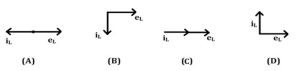
An $A.C.$ source is connected across a pure inductor. Which one of the following figures shows the correct phase relation between the current and $e.m.f.$?
A
$A$
B
$B$
C
$C$
D
$D$
Solution
(B) In a pure inductor,the current lags behind the applied $e.m.f.$ (voltage) by a phase angle of $90^{\circ}$ or $\pi/2$ radians.
If the voltage is represented as $e_L = E_0 \sin(\omega t)$,then the current is $i_L = I_0 \sin(\omega t - \pi/2)$.
In phasor diagrams,this means the current vector $i_L$ is $90^{\circ}$ clockwise from the voltage vector $e_L$.
Looking at the given options:
Figure $(A)$ shows them in opposite directions $(180^{\circ})$.
Figure $(B)$ shows $i_L$ lagging $e_L$ by $90^{\circ}$ (clockwise).
Figure $(C)$ shows them in phase $(0^{\circ})$.
Figure $(D)$ shows $i_L$ leading $e_L$ by $90^{\circ}$ (counter-clockwise).
Therefore,figure $(B)$ correctly represents the phase relationship.
0 likes
View Solution105
MediumMCQ
Same current is flowing in two different $A.C.$ circuits. The first circuit contains only an inductance $(L)$ and the second contains only a capacitance $(C)$. If the frequency of the $A.C.$ source is increased in both circuits, what will happen to the current?
A
increase in the first circuit and decrease in second.
B
increase in both circuits.
C
decrease in both circuits.
D
decrease in first circuit and increase in second.
Solution
(D) In an $A.C.$ circuit containing only an inductor, the inductive reactance is given by $X_L = 2\pi fL$. The current is $I = V / X_L = V / (2\pi fL)$. As frequency $f$ increases, $X_L$ increases, so the current $I$ decreases.
In an $A.C.$ circuit containing only a capacitor, the capacitive reactance is given by $X_C = 1 / (2\pi fC)$. The current is $I = V / X_C = V \cdot (2\pi fC)$. As frequency $f$ increases, $X_C$ decreases, so the current $I$ increases.
Therefore, the current decreases in the first circuit and increases in the second circuit.
0 likes
View Solution106
EasyMCQ
An $A.C.$ voltage is applied to a pure inductor. The current in the inductor
A
leads the voltage by $(\pi / 4)^c$
B
leads the voltage by $(\pi / 2)^c$
C
lags behind the voltage by $(\pi / 2)^c$
D
lags behind the voltage by $(3\pi / 4)^c$
Solution
(C) When an $A.C.$ voltage $V = V_m \sin(\omega t)$ is applied to a pure inductor of inductance $L$,the induced electromotive force $(EMF)$ is given by $\varepsilon = -L \frac{di}{dt}$.
Applying Kirchhoff's voltage law,$V - L \frac{di}{dt} = 0$,which implies $V = L \frac{di}{dt}$.
Substituting $V$,we get $V_m \sin(\omega t) = L \frac{di}{dt}$,so $di = \frac{V_m}{L} \sin(\omega t) dt$.
Integrating both sides,$i = \int \frac{V_m}{L} \sin(\omega t) dt = -\frac{V_m}{\omega L} \cos(\omega t) = \frac{V_m}{\omega L} \sin(\omega t - \pi / 2)$.
Comparing the phase of voltage $(\omega t)$ and current $(\omega t - \pi / 2)$,it is clear that the current lags behind the voltage by a phase angle of $\pi / 2$ radians.
0 likes
View Solution107
EasyMCQ
The reactance of a capacitor is $X_{C}$. If the frequency and the capacitance are doubled,then the new reactance will be
A
$X_{C}/2$
B
$X_{C}$
C
$X_{C}/4$
D
$2 X_{C}$
Solution
(C) The capacitive reactance $X_{C}$ is given by the formula $X_{C} = \frac{1}{2 \pi f C}$,where $f$ is the frequency and $C$ is the capacitance.
Let the initial reactance be $X_{C} = \frac{1}{2 \pi f C}$.
When the frequency $f$ is doubled $(f' = 2f)$ and the capacitance $C$ is doubled $(C' = 2C)$,the new reactance $X_{C}'$ is given by:
$X_{C}' = \frac{1}{2 \pi f' C'} = \frac{1}{2 \pi (2f) (2C)}$.
$X_{C}' = \frac{1}{4 (2 \pi f C)} = \frac{1}{4} X_{C}$.
Therefore,the new reactance is $\frac{X_{C}}{4}$.
0 likes
View Solution108
EasyMCQ
$L$, $C$ and $R$ are connected in series to an $A.C.$ source. Which one of the following is true? Phase relation between current and voltage is such that
A
both are out of phase with each other in $R$.
B
both are in phase in $L$ and out of phase in $C$.
C
both are out of phase in $L$ and in phase in $C$.
D
both are out of phase in both $C$ and $L$.
Solution
(D) In a series $LCR$ circuit connected to an $A.C.$ source:
$1$. In a pure resistor $(R)$, the current and voltage are always in phase.
$2$. In a pure inductor $(L)$, the voltage leads the current by a phase angle of $90^{\circ}$ ($\pi/2$ radians), meaning they are out of phase.
$3$. In a pure capacitor $(C)$, the current leads the voltage by a phase angle of $90^{\circ}$ ($\pi/2$ radians), meaning they are out of phase.
Therefore, in both the inductor $(L)$ and the capacitor $(C)$, the current and voltage are out of phase with each other. Thus, option $D$ is correct.
0 likes
View Solution109
EasyMCQ
The current flowing in a coil is $3 \text{ A}$ and the power consumed is $108 \text{ W}$. If the a.c. source is of $120 \text{ V}, 50 \text{ Hz}$,the resistance in the circuit is (in $Omega$)
A
$24$
B
$36$
C
$12$
D
$6$
Solution
(C) The power consumed in an $A$.$C$. circuit containing a resistor is given by the formula:
$P = I_{rms}^2 R$
Given:
$P = 108 \text{ W}$
$I_{rms} = 3 \text{ A}$
Substituting the values into the formula:
$108 = (3)^2 \times R$
$108 = 9 \times R$
$R = \frac{108}{9} = 12 \ \Omega$
Therefore,the resistance in the circuit is $12 \ \Omega$.
$P = I_{rms}^2 R$
Given:
$P = 108 \text{ W}$
$I_{rms} = 3 \text{ A}$
Substituting the values into the formula:
$108 = (3)^2 \times R$
$108 = 9 \times R$
$R = \frac{108}{9} = 12 \ \Omega$
Therefore,the resistance in the circuit is $12 \ \Omega$.
0 likes
View Solution110
EasyMCQ
$A$ $42 \, mH$ inductor is connected to a $200 \, V, 50 \, Hz$ a.c. supply. The r.m.s. value of current in the circuit will be nearly (Take $\pi = \frac{22}{7}$) (in $ \, A$)
A
$15.15$
B
$9.15$
C
$8.15$
D
$6.15$
Solution
(A) Given: Inductance $L = 42 \, mH = 42 \times 10^{-3} \, H$, Voltage $V_{rms} = 200 \, V$, Frequency $f = 50 \, Hz$.
First, calculate the inductive reactance $X_L$ using the formula $X_L = \omega L = 2 \pi f L$.
Substituting the values: $X_L = 2 \times \frac{22}{7} \times 50 \times 42 \times 10^{-3} \, \Omega$.
$X_L = 2 \times 22 \times 50 \times 6 \times 10^{-3} \, \Omega = 4400 \times 6 \times 10^{-3} \, \Omega = 13.2 \, \Omega$.
The r.m.s. current $I_{rms}$ is given by $I_{rms} = \frac{V_{rms}}{X_L}$.
$I_{rms} = \frac{200}{13.2} \approx 15.15 \, A$.
0 likes
View Solution111
EasyMCQ
Average power associated with an ideal inductor and ideal capacitor over a complete cycle of $a.c.$ is respectively
A
zero,one
B
one,zero
C
zero,zero
D
one,one
Solution
(C) $1$. Ideal Inductor:
- The voltage and current in an ideal inductor are out of phase by $90^{\circ}$,with the current lagging the voltage by $90^{\circ}$.
- The instantaneous power is given by $p(t) = v(t) \times i(t)$.
- Over a complete cycle,the positive and negative power values cancel out,resulting in an average power of zero.
$2$. Ideal Capacitor:
- In an ideal capacitor,the voltage and current are also out of phase by $90^{\circ}$,but the current leads the voltage by $90^{\circ}$.
- Similar to the inductor case,the instantaneous power alternates between positive and negative,resulting in an average power of zero over a complete cycle.
0 likes
View Solution112
MediumMCQ
The reactance of a capacitor at $50 \ Hz$ is $5 \ \Omega$. If the frequency is increased to $100 \ Hz$,the new reactance is (in $Omega$)
A
$5$
B
$2.5$
C
$10$
D
$125$
Solution
(B) The capacitive reactance $X_C$ is given by the formula: $X_C = \frac{1}{2 \pi f C}$.
From this,we can see that $X_C \propto \frac{1}{f}$.
Given initial frequency $f_1 = 50 \ Hz$ and initial reactance $X_{C1} = 5 \ \Omega$.
New frequency $f_2 = 100 \ Hz$.
Since $f_2 = 2 f_1$,the new reactance $X_{C2}$ will be:
$X_{C2} = \frac{X_{C1}}{2} = \frac{5 \ \Omega}{2} = 2.5 \ \Omega$.
From this,we can see that $X_C \propto \frac{1}{f}$.
Given initial frequency $f_1 = 50 \ Hz$ and initial reactance $X_{C1} = 5 \ \Omega$.
New frequency $f_2 = 100 \ Hz$.
Since $f_2 = 2 f_1$,the new reactance $X_{C2}$ will be:
$X_{C2} = \frac{X_{C1}}{2} = \frac{5 \ \Omega}{2} = 2.5 \ \Omega$.
0 likes
View Solution113
MediumMCQ
The inductive reactance of a coil is $X_{L}$. If the inductance of a coil is tripled and the frequency of the $A.C.$ supply is doubled,then the new inductive reactance will be
A
$\frac{2}{3} X_L$
B
$\frac{3}{2} X_L$
C
$\frac{1}{6} X_L$
D
$6 X_L$
Solution
(D) The inductive reactance is given by the formula $X_{L} = \omega L = 2 \pi f L$.
Given that the new frequency $f' = 2f$ and the new inductance $L' = 3L$.
The new inductive reactance $X_{L}'$ is calculated as:
$X_{L}' = 2 \pi f' L'$
$X_{L}' = 2 \pi (2f) (3L)$
$X_{L}' = 6 \times (2 \pi f L)$
Since $X_{L} = 2 \pi f L$,we have $X_{L}' = 6 X_{L}$.
Given that the new frequency $f' = 2f$ and the new inductance $L' = 3L$.
The new inductive reactance $X_{L}'$ is calculated as:
$X_{L}' = 2 \pi f' L'$
$X_{L}' = 2 \pi (2f) (3L)$
$X_{L}' = 6 \times (2 \pi f L)$
Since $X_{L} = 2 \pi f L$,we have $X_{L}' = 6 X_{L}$.
0 likes
View Solution114
DifficultMCQ
The capacitive reactance of a capacitor $C$ is $X \ \Omega$. Both the frequency of the $A.C.$ supply and the capacitance of the capacitor are doubled. The new capacitive reactance will be:
A
$\frac{X}{4} \ \Omega$
B
$\frac{X}{2} \ \Omega$
C
$2 X \ \Omega$
D
$4 X \ \Omega$
Solution
(A) The formula for capacitive reactance is $X_C = \frac{1}{2 \pi f C}$.
Given,the initial capacitive reactance is $X_C = X \ \Omega$.
So,$X = \frac{1}{2 \pi f C}$.
When the frequency is doubled $(f' = 2f)$ and the capacitance is doubled $(C' = 2C)$,the new capacitive reactance $X_C'$ is:
$X_C' = \frac{1}{2 \pi f' C'} = \frac{1}{2 \pi (2f) (2C)}$.
$X_C' = \frac{1}{4 (2 \pi f C)}$.
Since $X = \frac{1}{2 \pi f C}$,we substitute this into the equation:
$X_C' = \frac{X}{4} \ \Omega$.
0 likes
View Solution115
EasyMCQ
An alternating voltage $E = 200 \sqrt{2} \sin(100 t) \text{ V}$ is connected to a $1 \mu\text{F}$ capacitor through an $A.C.$ ammeter. The reading of the ammeter shall be: (in $\text{ mA}$)
A
$10$
B
$20$
C
$40$
D
$80$
Solution
(B) The given alternating voltage is $E = E_0 \sin(\omega t)$, where $E_0 = 200 \sqrt{2} \text{ V}$ and $\omega = 100 \text{ rad/s}$.
The capacitive reactance is $X_C = \frac{1}{\omega C} = \frac{1}{100 \times 1 \times 10^{-6}} = 10^4 \Omega$.
The peak current is $I_0 = \frac{E_0}{X_C} = \frac{200 \sqrt{2}}{10^4} = 2 \sqrt{2} \times 10^{-2} \text{ A}$.
The $A.C.$ ammeter measures the root mean square $(RMS)$ current, $I_{\text{rms}} = \frac{I_0}{\sqrt{2}}$.
$I_{\text{rms}} = \frac{2 \sqrt{2} \times 10^{-2}}{\sqrt{2}} = 2 \times 10^{-2} \text{ A} = 20 \text{ mA}$.
0 likes
View Solution116
MediumMCQ
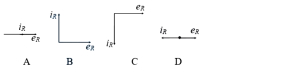
When an a.c. source is connected across a pure resistor,the correct phase relation between current $(i_R)$ and voltage $(e_R)$ is shown in which figure?
A
$(A)$
B
$(B)$
C
$(C)$
D
$(D)$
Solution
(C) In a pure resistive circuit,the voltage $(e_R)$ and current $(i_R)$ are in the same phase. This means that they reach their maximum and minimum values at the same time. The phase difference between them is $0$. Therefore,the phasor diagram representing this relationship shows both vectors pointing in the same direction,as depicted in figure $(A)$.
0 likes
View Solution117
EasyMCQ
An alternating voltage of $22 \, V$ is applied across an inductance coil of reactance $11 \, \Omega$. If the inductance of the coil is $0.07 \, H$, the frequency of the alternating voltage is: (in $ \, Hz$)
A
$25$
B
$40$
C
$50$
D
$20$
Solution
(A) The inductive reactance $X_L$ is given by the formula $X_L = \omega L$, where $\omega = 2 \pi f$.
Substituting the value of $\omega$, we get $X_L = 2 \pi f L$.
Given $X_L = 11 \, \Omega$ and $L = 0.07 \, H$, we can solve for frequency $f$:
$f = \frac{X_L}{2 \pi L} = \frac{11}{2 \times 3.14159 \times 0.07} \approx \frac{11}{0.4398} \approx 25 \, Hz$.
Thus, the frequency of the alternating voltage is $25 \, Hz$.
0 likes
View Solution118
MediumMCQ
The frequency for which a $5 \mu F$ capacitor has a reactance of $\frac{1}{1000} \Omega$ is given by
A
$\frac{1}{1000} \text{ Hz}$
B
$1000 \text{ Hz}$
C
$\frac{100}{\pi} \text{ MHz}$
D
$\frac{1000}{\pi} \text{ Hz}$
Solution
(C) The capacitive reactance $X_c$ is given by the formula: $X_c = \frac{1}{2 \pi f C}$.
Given values are $X_c = \frac{1}{1000} \Omega = 10^{-3} \Omega$ and $C = 5 \mu F = 5 \times 10^{-6} \text{ F}$.
Substituting these values into the formula:
$10^{-3} = \frac{1}{2 \pi f (5 \times 10^{-6})}$
$10^{-3} = \frac{1}{10 \pi f \times 10^{-6}}$
$10^{-3} = \frac{1}{\pi f \times 10^{-5}}$
Rearranging for frequency $f$:
$f = \frac{1}{10^{-3} \times \pi \times 10^{-5}} = \frac{1}{\pi \times 10^{-8}} = \frac{10^8}{\pi} \text{ Hz}$.
Since $1 \text{ MHz} = 10^6 \text{ Hz}$,we have $f = \frac{100 \times 10^6}{\pi} \text{ Hz} = \frac{100}{\pi} \text{ MHz}$.
0 likes
View Solution119
EasyMCQ
The coil of inductance $0.25 mH$ has a reactance of $330 \Omega$,when connected to an a.c. source. The frequency of the a.c. source is (Take $\pi = \frac{22}{7}$) (in $kHz$)
A
$210$
B
$105$
C
$420$
D
$330$
Solution
(A) The inductive reactance $X_L$ is given by the formula $X_L = 2 \pi f L$,where $f$ is the frequency and $L$ is the inductance.
Rearranging for frequency,we get $f = \frac{X_L}{2 \pi L}$.
Given values: $X_L = 330 \Omega$ and $L = 0.25 mH = 0.25 \times 10^{-3} H$.
Substituting the values: $f = \frac{330}{2 \times (22/7) \times 0.25 \times 10^{-3}}$.
$f = \frac{330 \times 7}{2 \times 22 \times 0.25 \times 10^{-3}} = \frac{2310}{11 \times 10^{-3}} = 210 \times 10^3 Hz = 210 kHz$.
0 likes
View Solution120
EasyMCQ
The resistance offered by the inductor $(X_L)$ in an ac circuit is
A
inversely proportional to inductance and directly proportional to the frequency of alternating current
B
inversely proportional to inductance and frequency of the alternating current
C
directly proportional to inductance and frequency of alternating current
D
inversely proportional to frequency of alternating current and directly proportional to inductance.
Solution
(C) The expression for inductive reactance $(X_L)$ is given by:
$X_L = 2 \pi f L$
Where $f$ is the frequency of the alternating current and $L$ is the inductance.
From the formula,it is clear that $X_L$ is directly proportional to both the frequency $(f)$ and the inductance $(L)$.
Therefore,$X_L \propto f$ and $X_L \propto L$.
$X_L = 2 \pi f L$
Where $f$ is the frequency of the alternating current and $L$ is the inductance.
From the formula,it is clear that $X_L$ is directly proportional to both the frequency $(f)$ and the inductance $(L)$.
Therefore,$X_L \propto f$ and $X_L \propto L$.
0 likes
View Solution121
EasyMCQ
$A$ capacitor of $50 \mu F$ is connected to an a.c. source $e = 220 \sin(50t)$ (where $e$ is in volts and $t$ is in seconds). The value of the peak current is:
A
$0.55 \sqrt{2} \text{ A}$
B
$\sqrt{2} \text{ A}$
C
$\frac{\sqrt{2}}{0.55} \text{ A}$
D
$0.55 \text{ A}$
Solution
(D) Given the voltage equation $e = 220 \sin(50t)$.
Comparing this with the standard form $e = E_0 \sin(\omega t)$,we get the peak voltage $E_0 = 220 \text{ V}$ and angular frequency $\omega = 50 \text{ rad/s}$.
The capacitive reactance $X_C$ is given by $X_C = \frac{1}{\omega C}$.
Substituting the values: $X_C = \frac{1}{50 \times 50 \times 10^{-6}} = \frac{1}{2500 \times 10^{-6}} = \frac{10^6}{2500} = 400 \Omega$.
The peak current $I_0$ is given by $I_0 = \frac{E_0}{X_C}$.
$I_0 = \frac{220}{400} = \frac{22}{40} = 0.55 \text{ A}$.
0 likes
View Solution122
EasyMCQ
The inductive reactance of a coil is $R$. If the inductance of the coil is doubled and the frequency of the $A.C.$ supply is also doubled,then the new inductive reactance will be:
A
$2 R$
B
$8 R$
C
$R/2$
D
$4 R$
Solution
(D) The formula for inductive reactance $(X_L)$ is given by $X_L = 2 \pi f L$,where $f$ is the frequency and $L$ is the inductance.
Given that the initial inductive reactance is $R = 2 \pi f L$.
If the new inductance $L' = 2L$ and the new frequency $f' = 2f$,the new inductive reactance $X_L'$ will be:
$X_L' = 2 \pi f' L' = 2 \pi (2f) (2L) = 4 (2 \pi f L) = 4R$.
Therefore,the new inductive reactance is $4R$.
Given that the initial inductive reactance is $R = 2 \pi f L$.
If the new inductance $L' = 2L$ and the new frequency $f' = 2f$,the new inductive reactance $X_L'$ will be:
$X_L' = 2 \pi f' L' = 2 \pi (2f) (2L) = 4 (2 \pi f L) = 4R$.
Therefore,the new inductive reactance is $4R$.
0 likes
View Solution123
EasyMCQ
$A$ parallel plate capacitor having plates of radius $6 \text{ cm}$ has capacitance $100 \text{ pF}$. It is connected to a $230 \text{ V}$ a.c. supply with angular frequency $300 \text{ rad/s}$. The r.m.s. value of current is:
A
$6.9 \times 10^{-6} \text{ A}$
B
$2.3 \times 10^{-5} \text{ A}$
C
$6.9 \times 10^{-5} \text{ A}$
D
$6.9 \times 10^{-7} \text{ A}$
Solution
(A) The r.m.s. current $I_{rms}$ in a capacitive circuit is given by $I_{rms} = \frac{V_{rms}}{X_C}$,where $X_C = \frac{1}{\omega C}$ is the capacitive reactance.
Substituting $X_C$,we get $I_{rms} = V_{rms} \cdot \omega \cdot C$.
Given values are $V_{rms} = 230 \text{ V}$,$\omega = 300 \text{ rad/s}$,and $C = 100 \text{ pF} = 100 \times 10^{-12} \text{ F}$.
$I_{rms} = 230 \times 300 \times 100 \times 10^{-12} \text{ A}$.
$I_{rms} = 230 \times 3 \times 10^4 \times 10^{-12} \text{ A}$.
$I_{rms} = 690 \times 10^{-8} \text{ A} = 6.9 \times 10^{-6} \text{ A}$.
0 likes
View Solution124
MediumMCQ
If we increase the frequency of an $a.c.$ supply,then inductive reactance
A
increases directly with the square of frequency
B
increases as it is directly proportional to frequency
C
decreases inversely with the square of frequency
D
decreases as it is inversely proportional to the frequency
Solution
(B) The inductive reactance $X_{L}$ of an inductor is given by the formula $X_{L} = 2 \pi f L$,where $f$ is the frequency of the $a.c.$ supply and $L$ is the self-inductance.
From this relation,it is clear that $X_{L} \propto f$.
Therefore,if the frequency $f$ increases,the inductive reactance $X_{L}$ also increases linearly.
From this relation,it is clear that $X_{L} \propto f$.
Therefore,if the frequency $f$ increases,the inductive reactance $X_{L}$ also increases linearly.
0 likes
View Solution125
EasyMCQ
In a capacitive circuit,the reactance of a capacitor at frequency $f$ is $X_{C}$. What will be its reactance at frequency $4f$?
A
$\frac{X_{C}}{2}$
B
$\frac{X_{C}}{4}$
C
$\frac{X_{C}}{8}$
D
$X_{C}$
Solution
(B) The capacitive reactance $X_{C}$ is given by the formula: $X_{C} = \frac{1}{2 \pi f C}$.
From this formula,it is clear that the capacitive reactance is inversely proportional to the frequency,i.e.,$X_{C} \propto \frac{1}{f}$.
Let the initial frequency be $f$ and the initial reactance be $X_{C}$.
Let the new frequency be $f' = 4f$ and the new reactance be $X_{C}'$.
Using the proportionality $X_{C} \cdot f = \text{constant}$,we get:
$X_{C}' \cdot f' = X_{C} \cdot f$
$X_{C}' \cdot (4f) = X_{C} \cdot f$
$X_{C}' = \frac{X_{C}}{4}$.
0 likes
View Solution126
MediumMCQ
An alternating voltage $e = 200 \sqrt{2} \sin(100 t) \text{ V}$ is connected to a $1 \mu F$ capacitor through an $AC$ ammeter. The reading of the ammeter is: (in $\text{ mA}$)
A
$5$
B
$10$
C
$15$
D
$20$
Solution
(D) The given alternating voltage is $e = e_0 \sin(\omega t)$, where $e_0 = 200 \sqrt{2} \text{ V}$ and $\omega = 100 \text{ rad/s}$.
The capacitive reactance is $X_C = \frac{1}{\omega C} = \frac{1}{100 \times 1 \times 10^{-6}} = \frac{1}{10^{-4}} = 10^4 \Omega$.
The $RMS$ voltage is $V_{rms} = \frac{e_0}{\sqrt{2}} = \frac{200 \sqrt{2}}{\sqrt{2}} = 200 \text{ V}$.
The reading of the $AC$ ammeter gives the $RMS$ current $I_{rms} = \frac{V_{rms}}{X_C}$.
Substituting the values, $I_{rms} = \frac{200}{10^4} = 2 \times 10^{-2} \text{ A} = 20 \text{ mA}$.
0 likes
View Solution127
MediumMCQ
$A$ choke coil is used as resistance in
A
$AC$ circuits
B
$DC$ circuits
C
half wave rectifier circuits
D
Both in $AC$ and $DC$ circuits
Solution
(A) choke coil is an inductor with high inductance and low resistance. It is used to control the current in $AC$ circuits without dissipating significant power as heat. In $DC$ circuits,an inductor acts as a simple wire with negligible resistance,so it cannot be used to control current effectively. Therefore,a choke coil is used as a resistance (impedance) in $AC$ circuits.
0 likes
View Solution128
EasyMCQ
In $AC$ circuits,a choke coil is preferred over resistors because:
A
choke coil is cheap
B
voltage increases
C
energy is not wasted
D
current increases
Solution
(C) In $AC$ circuits,a resistor dissipates energy in the form of heat due to the $I^2R$ loss,regardless of the phase difference.
However,an ideal choke coil is an inductor with negligible resistance.
In an ideal inductor,the phase difference between voltage and current is $90^{\circ}$,which makes the power factor $\cos(90^{\circ}) = 0$.
Therefore,the average power consumed by an ideal choke coil is $P = V_{rms} I_{rms} \cos(90^{\circ}) = 0$.
Thus,a choke coil controls the current in an $AC$ circuit without wasting electrical energy as heat.
0 likes
View Solution129
DifficultMCQ
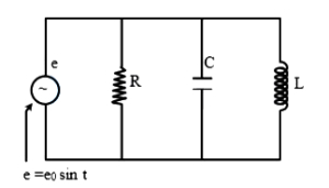
For the circuit shown below,the instantaneous current through the inductor '$L$' and the capacitor '$C$' is respectively. (Given $e = e_0 \sin \omega t$)
A
$\frac{-e_0}{\omega L} \cos \omega t ; e_0 \omega C \cos \omega t$
B
$\frac{-e_0}{\omega L} \sin \omega t ; \frac{e_0}{\omega C} \cos \omega t$
C
$\frac{e_0 C}{L} \cos \omega t ; \frac{e_0 L}{C} \sin \omega t$
D
$\frac{-e_0 C}{L} \sin \omega t ; \frac{e_0 L}{C} \cos \omega t$
Solution
(A) The applied voltage is $e = e_0 \sin \omega t$.
In an inductor,the current lags the voltage by $\frac{\pi}{2}$. The inductive reactance is $X_L = \omega L$. Thus,the instantaneous current $i_L$ is:
$i_L = \frac{e_0}{\omega L} \sin \left(\omega t - \frac{\pi}{2}\right) = -\frac{e_0}{\omega L} \cos \omega t$
In a capacitor,the current leads the voltage by $\frac{\pi}{2}$. The capacitive reactance is $X_C = \frac{1}{\omega C}$. Thus,the instantaneous current $i_C$ is:
$i_C = \frac{e_0}{X_C} \sin \left(\omega t + \frac{\pi}{2}\right) = e_0 \omega C \cos \omega t$
Therefore,the currents are $-\frac{e_0}{\omega L} \cos \omega t$ and $e_0 \omega C \cos \omega t$.
0 likes
View Solution130
EasyMCQ
For a purely inductive or a purely capacitive circuit,the power factor is
A
zero
B
$0.5$
C
$1$
D
$\infty$
Solution
(A) The power factor of an $AC$ circuit is defined as $\cos \phi$,where $\phi$ is the phase difference between the voltage and the current.
In a purely inductive circuit,the current lags behind the voltage by a phase angle of $\phi = 90^\circ$ (or $\pi/2$ radians).
In a purely capacitive circuit,the current leads the voltage by a phase angle of $\phi = 90^\circ$ (or $\pi/2$ radians).
Therefore,the power factor is $\cos(90^\circ) = 0$ for both cases.
0 likes
View Solution131
MediumMCQ
In a circuit,the current lags behind the voltage by a phase difference of $\pi / 2$. The circuit will contain which of the following?
A
Only $R$
B
Only $C$
C
$R$ and $C$
D
Only $L$
Solution
(D) In an alternating current circuit,the phase relationship between voltage and current depends on the components present.
For a purely inductive circuit (containing only an inductor $L$),the voltage leads the current by a phase angle of $\pi / 2$ $(90^{\circ})$,which is equivalent to saying the current lags behind the voltage by $\pi / 2$.
For a purely capacitive circuit (containing only a capacitor $C$),the current leads the voltage by a phase angle of $\pi / 2$ $(90^{\circ})$.
For a purely resistive circuit (containing only a resistor $R$),the current and voltage are in the same phase (phase difference is $0$).
Therefore,since the current lags behind the voltage by $\pi / 2$,the circuit must contain only an inductor $L$.
0 likes
View Solution132
EasyMCQ
$A$ coil has inductance $L$. The ratio of its reactance when it is connected first to an $A.C.$ source and then to a $D.C.$ source is
A
$\infty$
B
zero
C
one
D
two
Solution
(A) The reactance of an inductor in an $A.C.$ circuit is given by $X_L = \omega L = 2\pi f L$,where $f$ is the frequency of the $A.C.$ source.
For a $D.C.$ source,the frequency $f = 0$.
Therefore,the inductive reactance in a $D.C.$ circuit is $X_L = 2\pi (0) L = 0$.
The ratio of reactance in an $A.C.$ source to that in a $D.C.$ source is $\frac{X_{L(ac)}}{X_{L(dc)}} = \frac{\omega L}{0} = \infty$.
For a $D.C.$ source,the frequency $f = 0$.
Therefore,the inductive reactance in a $D.C.$ circuit is $X_L = 2\pi (0) L = 0$.
The ratio of reactance in an $A.C.$ source to that in a $D.C.$ source is $\frac{X_{L(ac)}}{X_{L(dc)}} = \frac{\omega L}{0} = \infty$.
0 likes
View Solution133
EasyMCQ
$A$ pure inductor of $50.0 \ mH$ is connected to a source of $220 \ V$. The frequency of the source is $50 \ Hz$. The rms current in the circuit (in $A$) will be $......$.
A
$28$
B
$7$
C
$14$
D
$21$
Solution
(C) Step $1$: Given values:
$V = 220 \ V$
$L = 50 \ mH = 50 \times 10^{-3} \ H$
$\nu = 50 \ Hz$
Step $2$: The inductive reactance $X_L$ is given by $X_L = \omega L = 2 \pi \nu L$.
Step $3$: The rms current $I$ is given by $I = \frac{V}{X_L} = \frac{V}{2 \pi \nu L}$.
Step $4$: Substituting the values:
$I = \frac{220}{2 \times 3.14159 \times 50 \times 50 \times 10^{-3}}$
$I = \frac{220}{15.70795} \approx 14.005 \ A$.
Thus,the rms current is approximately $14 \ A$.
0 likes
View Solution134
EasyMCQ
For obtaining wattless current . . . . . . is connected with ac supply.
A
$R$-$C$ series
B
$R$-$L$ series
C
Only $L$
D
Only $R$
Solution
(C) Wattless current is defined as the current in an $AC$ circuit for which the average power consumed is zero.
Power in an $AC$ circuit is given by $P = V_{rms} I_{rms} \cos \phi$, where $\phi$ is the phase angle between voltage and current.
For $P$ to be zero, $\cos \phi$ must be zero, which implies $\phi = 90^{\circ}$.
In a purely inductive circuit (Only $L$) or a purely capacitive circuit (Only $C$), the phase difference between voltage and current is $90^{\circ}$.
Therefore, in a circuit containing only an ideal inductor (Only $L$) or only an ideal capacitor, the power factor $\cos 90^{\circ} = 0$, resulting in wattless current.
Among the given options, Only $L$ is the correct choice.
0 likes
View Solution135
EasyMCQ
$A$ $50 \mu F$ capacitor is connected to a $110 V, 60 Hz$ $AC$ supply. Determine the rms value of the current in the circuit. (in $A$)
A
$2.5$
B
$3.8$
C
$5.2$
D
$2.1$
Solution
(D) Given: Capacitance $C = 50 \mu F = 50 \times 10^{-6} F$,Voltage $V_{rms} = 110 V$,Frequency $\nu = 60 Hz$.
First,calculate the capacitive reactance $X_C$ using the formula $X_C = \frac{1}{2 \pi \nu C}$.
$X_C = \frac{1}{2 \times 3.1416 \times 60 \times 50 \times 10^{-6}} \approx 53.05 \Omega$.
The rms current $I_{rms}$ is given by $I_{rms} = \frac{V_{rms}}{X_C}$.
$I_{rms} = \frac{110}{53.05} \approx 2.07 A$.
Rounding to one decimal place,we get $I_{rms} = 2.1 A$.
0 likes
View Solution136
EasyMCQ
$A$ capacitor '$C$' is connected across a $DC$ source,the reactance of the capacitance will be . . . . . . .
A
Zero
B
High
C
Low
D
Infinite
Solution
(D) The capacitive reactance $X_C$ is given by the formula $X_C = \frac{1}{2 \pi \nu C}$,where $\nu$ is the frequency of the source.
For a $DC$ source,the frequency $\nu = 0 \ Hz$.
Substituting this value into the formula,we get $X_C = \frac{1}{2 \pi (0) C} = \frac{1}{0}$.
Therefore,the reactance of the capacitor in a $DC$ circuit is infinite.
For a $DC$ source,the frequency $\nu = 0 \ Hz$.
Substituting this value into the formula,we get $X_C = \frac{1}{2 \pi (0) C} = \frac{1}{0}$.
Therefore,the reactance of the capacitor in a $DC$ circuit is infinite.
0 likes
View Solution137
EasyMCQ
An alternating voltage given as $V = 100 \sqrt{2} \sin(100t) \text{ V}$ is applied to a capacitor of $1 \mu\text{F}$. The current reading of the ammeter will be equal to . . . . . . $\text{mA}$.
A
$10$
B
$20$
C
$40$
D
$80$
Solution
(A) The given alternating voltage is $V = 100 \sqrt{2} \sin(100t) \text{ V}$.
Comparing this with the standard form $V = V_m \sin(\omega t)$,we get the peak voltage $V_m = 100 \sqrt{2} \text{ V}$ and angular frequency $\omega = 100 \text{ rad/s}$.
The capacitive reactance is given by $X_C = \frac{1}{\omega C}$.
Substituting the values,$X_C = \frac{1}{100 \times 1 \times 10^{-6}} = \frac{1}{10^{-4}} = 10^4 \text{ } \Omega$.
The root mean square $(RMS)$ voltage is $V_{\text{rms}} = \frac{V_m}{\sqrt{2}} = \frac{100 \sqrt{2}}{\sqrt{2}} = 100 \text{ V}$.
The $RMS$ current $I_{\text{rms}}$ is given by $I_{\text{rms}} = \frac{V_{\text{rms}}}{X_C}$.
$I_{\text{rms}} = \frac{100}{10^4} = 10^{-2} \text{ A}$.
Converting to milliamperes,$I_{\text{rms}} = 10^{-2} \times 10^3 \text{ mA} = 10 \text{ mA}$.
0 likes
View Solution138
EasyMCQ
In an $AC$ circuit having only a capacitor,the current . . . . . . .
A
lags behind the voltage by $\frac{\pi}{2}$ in phase.
B
leads the voltage by $\frac{\pi}{2}$ in phase.
C
leads the voltage by $\pi$ in phase.
D
lags behind the voltage by $\pi$ in phase.
Solution
(B) In a purely capacitive $AC$ circuit,the voltage $V$ is given by $V = V_m \sin(\omega t)$ and the current $I$ is given by $I = I_m \sin(\omega t + \frac{\pi}{2})$.
This shows that the current leads the voltage by a phase angle of $\frac{\pi}{2}$ radians.
Therefore,the correct option is $B$.
This shows that the current leads the voltage by a phase angle of $\frac{\pi}{2}$ radians.
Therefore,the correct option is $B$.
0 likes
View Solution139
EasyMCQ
If the capacitance of a pure capacitor in a $DC$ circuit is $1 \ F$,then what will be its capacitive reactance?
A
Zero
B
$1 \ \Omega$
C
Infinite
D
$-2$
Solution
(C) The correct option is $C$.
In a $DC$ circuit,the frequency $v = 0 \ Hz$.
The angular frequency is given by $\omega = 2 \pi v = 2 \pi \times 0 = 0 \ rad/s$.
The capacitive reactance $X_C$ is given by the formula $X_C = \frac{1}{\omega C}$.
Substituting the values,we get $X_C = \frac{1}{0 \times 1} = \frac{1}{0} = \infty$.
Therefore,the capacitive reactance of a capacitor in a $DC$ circuit is infinite,meaning it acts as an open circuit.
0 likes
View Solution140
EasyMCQ
What is the average power dissipation in an ideal capacitor in an $AC$ circuit?
A
$\frac{1}{2} CV^{2}$
B
$CV^{2}$
C
$2 CV^{2}$
D
Zero
Solution
(D) The average power dissipation $P$ in an $AC$ circuit is given by the formula $P = V_{rms} I_{rms} \cos \phi$,where $\phi$ is the phase difference between voltage and current.
For an ideal capacitor,the current leads the voltage by a phase angle of $\phi = \frac{\pi}{2}$ rad.
Substituting this into the power formula:
$P = V_{rms} I_{rms} \cos(\frac{\pi}{2})$
Since $\cos(\frac{\pi}{2}) = 0$,the average power dissipation is $P = 0$.
For an ideal capacitor,the current leads the voltage by a phase angle of $\phi = \frac{\pi}{2}$ rad.
Substituting this into the power formula:
$P = V_{rms} I_{rms} \cos(\frac{\pi}{2})$
Since $\cos(\frac{\pi}{2}) = 0$,the average power dissipation is $P = 0$.
0 likes
View Solution141
EasyMCQ
Inductive reactance . . . . . .
A
limits $A$.$C$. current
B
limits $DC$ voltage
C
limits $DC$ current
D
Stores the $AC$ current
Solution
(A) The correct answer is $A$. Inductive reactance $(X_L)$ is defined as the opposition offered by an inductor to the flow of alternating current.
$X_L = \omega L = 2 \pi f L$
where $f$ is the frequency of the $AC$ source and $L$ is the inductance.
Since $X_L$ is directly proportional to the frequency $(f)$,it effectively limits the flow of alternating current in a circuit.
For $DC$ circuits,the frequency $f = 0$,which means $X_L = 0$. Therefore,a pure inductor offers no resistance to $DC$ current.
0 likes
View Solution142
EasyMCQ
Which of the following graphs represents the variation of inductive reactance $(X_{L})$ with the frequency of the voltage source $(\nu)$?
A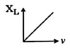
B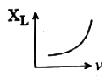
C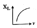
D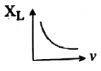
Solution
(A) The inductive reactance is given by the formula $X_{L} = \omega L$.
Here,$\omega = 2\pi\nu$,where $\nu$ is the frequency of the voltage source.
Substituting this into the formula,we get $X_{L} = 2\pi\nu L$.
Since $2$,$\pi$,and $L$ are constants,we have $X_{L} \propto \nu$.
This represents a linear relationship between inductive reactance and frequency,which is a straight line passing through the origin.
Therefore,the graph in option $A$ correctly represents this variation.
0 likes
View Solution143
MediumMCQ
$A$ capacitor of capacitance $10 \mu F$ is connected to an $AC$ source and an $AC$ Ammeter. If the source voltage varies as $V = 50 \sqrt{2} \sin 100 t$, the reading of the ammeter is (in $\text{ mA}$)
A
$50$
B
$70.7$
C
$5.0$
D
$7.07$
Solution
(A) Given: Capacitance $C = 10 \mu F = 10 \times 10^{-6} \text{ F}$.
Source voltage $V = 50 \sqrt{2} \sin 100 t$.
Comparing this with $V = V_{\max} \sin \omega t$, we get $V_{\max} = 50 \sqrt{2} \text{ V}$ and $\omega = 100 \text{ rad/s}$.
The capacitive reactance is $X_C = \frac{1}{\omega C} = \frac{1}{100 \times 10 \times 10^{-6}} = \frac{1}{10^{-3}} = 1000 \Omega$.
The $RMS$ voltage is $V_{\text{rms}} = \frac{V_{\max}}{\sqrt{2}} = \frac{50 \sqrt{2}}{\sqrt{2}} = 50 \text{ V}$.
The reading of the $AC$ ammeter gives the $RMS$ current $I_{\text{rms}}$, which is $I_{\text{rms}} = \frac{V_{\text{rms}}}{X_C} = \frac{50}{1000} = 0.05 \text{ A}$.
Converting to milliamperes, $I_{\text{rms}} = 0.05 \times 1000 \text{ mA} = 50 \text{ mA}$.
0 likes
View Solution144
EasyMCQ
The average power dissipated in a pure inductor is
A
$ \frac{1}{2} VI $
B
$ VI^{2} $
C
$ \frac{VI^{2}}{4} $
D
zero
Solution
(D) The average power dissipated in an $AC$ circuit is given by the formula $ P_{av} = VI \cos \phi $,where $ V $ is the $RMS$ voltage,$ I $ is the $RMS$ current,and $ \phi $ is the phase angle between voltage and current.
In a pure inductor,the current lags behind the voltage by a phase angle of $ \phi = \pi / 2 $.
Substituting this into the power formula: $ P_{av} = VI \cos(\pi / 2) $.
Since $ \cos(\pi / 2) = 0 $,we get $ P_{av} = VI \times 0 = 0 $.
Therefore,the average power dissipated in a pure inductor is zero.
In a pure inductor,the current lags behind the voltage by a phase angle of $ \phi = \pi / 2 $.
Substituting this into the power formula: $ P_{av} = VI \cos(\pi / 2) $.
Since $ \cos(\pi / 2) = 0 $,we get $ P_{av} = VI \times 0 = 0 $.
Therefore,the average power dissipated in a pure inductor is zero.
0 likes
View Solution145
MediumMCQ
Capacitive reactance of a capacitor in an $AC$ circuit is $3 \ k\Omega$. If this capacitor is connected to a new $AC$ source of double frequency,the capacitive reactance will become:
A
$1.5 \ k\Omega$
B
$3 \ k\Omega$
C
$6 \ k\Omega$
D
$5.2 \ k\Omega$
Solution
(A) The capacitive reactance $X_C$ of a capacitor is given by the formula: $X_C = \frac{1}{2 \pi f C}$.
Here,$f$ is the frequency of the $AC$ source and $C$ is the capacitance.
From the formula,it is clear that $X_C \propto \frac{1}{f}$.
Given,initial capacitive reactance $X_{C1} = 3 \ k\Omega$ at frequency $f_1 = f$.
When the frequency is doubled,$f_2 = 2f$.
The new capacitive reactance $X_{C2}$ will be: $X_{C2} = \frac{1}{2 \pi (2f) C} = \frac{1}{2} \times \left( \frac{1}{2 \pi f C} \right) = \frac{X_{C1}}{2}$.
Substituting the value: $X_{C2} = \frac{3 \ k\Omega}{2} = 1.5 \ k\Omega$.
0 likes
View Solution146
MediumMCQ
$A$ $70 mH$ inductor is connected to a $220 V, 50 Hz$ $AC$ supply. The rms value of the current in the circuit is:
A
$\frac{100}{\sqrt{2} \pi} A$
B
$10 A$
C
$\frac{50}{\pi} A$
D
$\frac{10 \sqrt{2}}{\pi} A$
Solution
(B) Given: Inductance $L = 70 mH = 70 \times 10^{-3} H$,Voltage $V_{rms} = 220 V$,Frequency $f = 50 Hz$.
Inductive reactance is given by $\chi_{L} = \omega L = 2 \pi f L$.
Substituting the values: $\chi_{L} = 2 \times \pi \times 50 \times 70 \times 10^{-3} = 7 \pi \Omega$.
The rms current is $i_{rms} = \frac{V_{rms}}{\chi_{L}} = \frac{220}{7 \pi} \approx \frac{10}{\pi} A$ (Note: Based on standard textbook values,if $L = 70 mH$,the result is $\frac{220}{7 \pi} A$. However,checking the options,if $L = 70 mH$ and $V = 220 V$,the calculation yields $10 A$ only if $\pi \approx 3.14$ and $L$ was adjusted. Re-evaluating: $i_{rms} = \frac{220}{2 \pi \times 50 \times 70 \times 10^{-3}} = \frac{220}{7 \pi} \approx 10 A$ is not exact. Given the options,$10 A$ is the intended answer assuming approximation or specific values).
0 likes
View Solution147
EasyMCQ
$A$ $\frac{50}{\pi} \mu F$ capacitor is connected to a $250 \, V, 50 \, Hz$ $AC$ supply. Then the rms current of the circuit is (in $ \, A$)
A
$1.25$
B
$4.9$
C
$5$
D
$6$
Solution
(A) Given: Capacitance $C = \frac{50}{\pi} \mu F = \frac{50}{\pi} \times 10^{-6} \, F$.
Source voltage $V_{rms} = 250 \, V$ and frequency $f = 50 \, Hz$.
The capacitive reactance $X_C$ is given by the formula $X_C = \frac{1}{2 \pi f C}$.
Substituting the values: $X_C = \frac{1}{2 \pi \times 50 \times (\frac{50}{\pi} \times 10^{-6})} = \frac{1}{100 \times 50 \times 10^{-6}} = \frac{1}{5000 \times 10^{-6}} = \frac{1}{0.005} = 200 \, \Omega$.
The rms current $I_{rms}$ is given by $I_{rms} = \frac{V_{rms}}{X_C}$.
$I_{rms} = \frac{250}{200} = 1.25 \, A$.
0 likes
View Solution148
EasyMCQ
$A$ $100 \mu F$ capacitor is connected to a $100 \text{ V}$, $50 \text{ Hz}$ $AC$ supply. The rms value of the current is (in $\text{ A}$)
A
$3.14$
B
$4.75$
C
$2.33$
D
$5.5$
Solution
(A) Given: $V_{rms} = 100 \text{ V}$, $f = 50 \text{ Hz}$, $C = 100 \mu F = 100 \times 10^{-6} \text{ F}$.
First, calculate the capacitive reactance $X_C$ using the formula $X_C = \frac{1}{2 \pi f C}$.
$X_C = \frac{1}{2 \times \pi \times 50 \times 100 \times 10^{-6}} = \frac{1}{100 \pi \times 10^{-4}} = \frac{1}{0.01 \pi} = \frac{100}{\pi} \Omega$.
The rms value of the current $I_{rms}$ is given by $I_{rms} = \frac{V_{rms}}{X_C}$.
$I_{rms} = \frac{100}{100 / \pi} = \pi \text{ A}$.
Since $\pi \approx 3.14$, the current is $3.14 \text{ A}$.
0 likes
View SolutionAlternating Current — Only Inductor, Only Capacitor and Only Resistor Circuit · Frequently Asked Questions
1Are these Alternating Current questions useful for JEE and NEET?
Yes. All questions in this section are mapped to JEE Main and NEET exam patterns. Previous year questions from JEE Main, NEET, GUJCET and state-level exams are included with full solutions.
2Can I switch to Hindi or Gujarati for these questions?
Yes. Use the language tabs in the hero section or the sidebar to view the same questions and solutions in English, Hindi or Gujarati.
3How do I generate a question paper from this subtopic?
Use the Vedclass Exam Paper Generator — select the chapter and subtopic, set difficulty, and generate Sets A, B, C, D automatically. First 3 chapters of every subject are free.
Vedclass Products
For Students
Vedclass Test Series
Mock tests in real JEE/NEET style with performance analysis. 5-day free trial.
Start Free TrialFor Teachers
Exam Paper Generator
Generate Set A/B/C/D papers from this chapter in 2 minutes. 3 chapters free.
Try FreeFor Institutes
Online Exam Module
Live online exams with unlimited students, 360° analytics & white-label branding.
See DemoFor Teachers & Institutes
Generate a Alternating Current Exam Paper in 2 Minutes
Select subtopic & difficulty — Sets A, B, C, D auto-generated with No Repeat logic.
First 3 chapters of every subject are free — no payment required.