
A English
Only Inductor, Only Capacitor and Only Resistor Circuit Questions in English
Class 12 Physics · Alternating Current · Only Inductor, Only Capacitor and Only Resistor Circuit
166+
Questions
English
Language
100%
With Solutions
Showing 50 of 166 questions in English
51
Medium
$A$ $15.0 \; \mu F$ capacitor is connected to a $220 \; V, 50 \; Hz$ source. Find the capacitive reactance and the current ($rms$ and peak) in the circuit. If the frequency is doubled,what happens to the capacitive reactance and the current?
Solution
(N/A) The capacitive reactance is given by $X_{C} = \frac{1}{2 \pi \nu C}$.
Substituting the values: $X_{C} = \frac{1}{2 \pi (50 \; Hz) (15.0 \times 10^{-6} \; F)} \approx 212 \; \Omega$.
The $rms$ current is $I_{rms} = \frac{V_{rms}}{X_{C}} = \frac{220 \; V}{212 \; \Omega} \approx 1.04 \; A$.
The peak current is $I_{m} = \sqrt{2} I_{rms} = 1.414 \times 1.04 \; A \approx 1.47 \; A$.
If the frequency $\nu$ is doubled,the capacitive reactance $X_{C} = \frac{1}{2 \pi \nu C}$ becomes half of its original value. Since $I = \frac{V}{X_{C}}$,the current in the circuit doubles.
0 likes
View Solution52
Medium
$A$ $100 \; \Omega$ resistor is connected to a $220 \; V, 50 \; Hz$ $ac$ supply.
$(a)$ What is the $rms$ value of current in the circuit?
$(b)$ What is the net power consumed over a full cycle?
$(a)$ What is the $rms$ value of current in the circuit?
$(b)$ What is the net power consumed over a full cycle?
Solution
(N/A) Given:
Resistance $R = 100 \; \Omega$
Voltage $V_{rms} = 220 \; V$
Frequency $f = 50 \; Hz$
$(a)$ The $rms$ value of current $I_{rms}$ is given by:
$I_{rms} = \frac{V_{rms}}{R}$
$I_{rms} = \frac{220}{100} = 2.2 \; A$
$(b)$ The net power consumed over a full cycle in a purely resistive circuit is given by:
$P = V_{rms} \times I_{rms}$
$P = 220 \times 2.2 = 484 \; W$
0 likes
View Solution53
MediumMCQ
$A$ $44 \; mH$ inductor is connected to $220 \; V, 50 \; Hz$ $ac$ supply. Determine the $rms$ value of the current (in $A$) in the circuit.
A
$11.96$
B
$15.92$
C
$18.34$
D
$22.42$
Solution
(B) Given: Inductance $L = 44 \; mH = 44 \times 10^{-3} \; H$,Voltage $V_{rms} = 220 \; V$,Frequency $f = 50 \; Hz$.
The inductive reactance $X_L$ is given by the formula $X_L = \omega L = 2 \pi f L$.
Substituting the values: $X_L = 2 \times 3.1416 \times 50 \times 44 \times 10^{-3} \; \Omega$.
$X_L = 314.16 \times 44 \times 10^{-3} \; \Omega = 13.823 \; \Omega$.
The $rms$ current $I_{rms}$ is calculated as $I_{rms} = \frac{V_{rms}}{X_L}$.
$I_{rms} = \frac{220}{13.823} \approx 15.92 \; A$.
Thus,the $rms$ value of the current is $15.92 \; A$.
0 likes
View Solution54
MediumMCQ
$A$ $60\; \mu F$ capacitor is connected to a $110\; V, 60\; Hz$ $ac$ supply. Determine the $rms$ value of the current in the circuit. (in $; A$)
A
$8.4$
B
$6.3$
C
$2.5$
D
$5.1$
Solution
(C) Given: Capacitance $C = 60\; \mu F = 60 \times 10^{-6}\; F$,Voltage $V_{rms} = 110\; V$,Frequency $f = 60\; Hz$.
The capacitive reactance $X_C$ is given by the formula $X_C = \frac{1}{2\pi f C}$.
Substituting the values: $X_C = \frac{1}{2 \times 3.1416 \times 60 \times 60 \times 10^{-6}}$.
$X_C = \frac{1}{0.022619} \approx 44.21\; \Omega$.
The $rms$ current $I_{rms}$ is given by $I_{rms} = \frac{V_{rms}}{X_C}$.
$I_{rms} = \frac{110}{44.21} \approx 2.488\; A$.
Rounding to one decimal place,we get $I_{rms} \approx 2.5\; A$.
0 likes
View Solution55
Medium
$A$ $44 \; mH$ inductor is connected to a $220 \; V, 50 \; Hz$ $AC$ supply,and a $60 \; \mu F$ capacitor is connected to a $110 \; V, 60 \; Hz$ $AC$ supply. What is the net power absorbed by each circuit over a complete cycle? Explain your answer.
Solution
(A) The net power absorbed in an $AC$ circuit is given by the formula $P = V_{rms} I_{rms} \cos \phi$,where $\phi$ is the phase difference between voltage and current.
$1$. For the inductive circuit:
In a pure inductor,the current lags behind the voltage by a phase angle of $\phi = 90^{\circ}$.
The power factor is $\cos 90^{\circ} = 0$.
Therefore,the net power absorbed $P = V_{rms} I_{rms} \times 0 = 0 \; W$.
$2$. For the capacitive circuit:
In a pure capacitor,the current leads the voltage by a phase angle of $\phi = 90^{\circ}$.
The power factor is $\cos 90^{\circ} = 0$.
Therefore,the net power absorbed $P = V_{rms} I_{rms} \times 0 = 0 \; W$.
In both cases,the net power absorbed over a complete cycle is zero because pure inductors and pure capacitors do not dissipate energy; they only store and release it.
0 likes
View Solution56
Medium
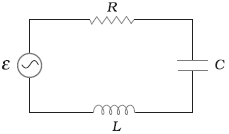
Keeping the source frequency equal to the resonating frequency of the series $LCR$ circuit,if the three elements,$L, C$ and $R$ are arranged in parallel,show that the total current in the parallel $LCR$ circuit is minimum at this frequency. Obtain the $rms$ current value in each branch of the circuit given below.
Figure shows a series $LCR$ circuit connected to a variable frequency $230\; V$ source. $L=5.0\; H, C=80\; \mu F, R=40\; \Omega$.
Figure shows a series $LCR$ circuit connected to a variable frequency $230\; V$ source. $L=5.0\; H, C=80\; \mu F, R=40\; \Omega$.
Solution
(N/A) An inductor $(L)$,a capacitor $(C)$,and a resistor $(R)$ are connected in parallel with each other in a circuit.
Given:
$L = 5.0\; H$
$C = 80\; \mu F = 80 \times 10^{-6}\; F$
$R = 40\; \Omega$
$V = 230\; V$
The impedance $(Z)$ of the given parallel $LCR$ circuit is given by:
$\frac{1}{Z} = \sqrt{\frac{1}{R^2} + \left(\frac{1}{\omega L} - \omega C\right)^2}$
At resonance,the reactive part is zero,i.e.,$\frac{1}{\omega L} - \omega C = 0$.
Therefore,the resonant angular frequency is:
$\omega = \frac{1}{\sqrt{LC}} = \frac{1}{\sqrt{5.0 \times 80 \times 10^{-6}}} = \frac{1}{\sqrt{400 \times 10^{-6}}} = \frac{1}{0.02} = 50\; rad/s$.
At this frequency,the term $(\frac{1}{\omega L} - \omega C)^2$ becomes zero,making $\frac{1}{Z}$ minimum,which means the impedance $Z$ is maximum. Consequently,the total current $I = \frac{V}{Z}$ is minimum.
The $rms$ current in each branch is:
$1$. Current through inductor $(I_L)$:
$I_L = \frac{V}{\omega L} = \frac{230}{50 \times 5.0} = \frac{230}{250} = 0.92\; A$.
$2$. Current through capacitor $(I_C)$:
$I_C = V \omega C = 230 \times 50 \times 80 \times 10^{-6} = 230 \times 4000 \times 10^{-6} = 0.92\; A$.
$3$. Current through resistor $(I_R)$:
$I_R = \frac{V}{R} = \frac{230}{40} = 5.75\; A$.
0 likes
View Solution57
Medium
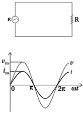
Explain $AC$ voltage applied to a resistor and explain it with a necessary graph.
Solution
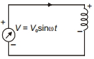
(N/A) Consider a resistor of resistance $R$ connected to an $AC$ voltage source. The source produces a sinusoidally varying potential difference across its terminals,given by:
$V = V_{m} \sin \omega t$ .....$(1)$
where $V_{m}$ is the amplitude of the oscillating potential difference (maximum voltage) and $\omega$ is its angular frequency.
Applying Kirchhoff's loop rule to the circuit:
$V - IR = 0$
$\therefore IR = V_{m} \sin \omega t$
$\therefore I = \frac{V_{m}}{R} \sin \omega t$
Since the current amplitude $I_{m} = \frac{V_{m}}{R}$ (Ohm's law),we can write:
$I = I_{m} \sin \omega t$ .....$(2)$
From equations $(1)$ and $(2)$,we see that the voltage and current are in phase,meaning they reach their maximum and minimum values at the same time. The graph below shows the variation of voltage $v$ and current $i$ as a function of $\omega t$.
0 likes
View Solution58
Difficult
Explain the dissipation of electrical energy when an alternating current passes through a resistor.
Solution
(N/A) In an $A.C.$ circuit, the voltage and current vary sinusoidally. The sum of the instantaneous current values over one complete cycle is zero, meaning the average current is zero.
However, the fact that the average current is zero does not mean that the average power consumed is zero or that there is no dissipation of electrical energy. Joule heating is given by $H = I^{2}Rt$, which depends on $I^{2}$. Since $I^{2}$ is always positive regardless of whether $I$ is positive or negative, energy is dissipated.
The instantaneous power dissipated in the resistor is:
$P = I^{2}R = (I_{m} \sin \omega t)^{2} R = I_{m}^{2} R \sin^{2} \omega t$
The average power $\bar{P}$ over a cycle is:
$\bar{P} = \langle P \rangle = \langle I^{2} R \rangle = I_{m}^{2} R \langle \sin^{2} \omega t \rangle$
Using the trigonometric identity $\sin^{2} \omega t = \frac{1 - \cos 2\omega t}{2}$, we find the average value over a cycle:
$\langle \sin^{2} \omega t \rangle = \langle \frac{1}{2} - \frac{1}{2} \cos 2\omega t \rangle = \frac{1}{2} - 0 = \frac{1}{2}$
Therefore, the average power dissipated is:
$\bar{P} = \frac{1}{2} I_{m}^{2} R$
0 likes
View Solution59
EasyMCQ
What is the phase difference between $V$ and $I$ in a circuit containing only a resistor?
A
$0$
B
$\pi/2$
C
$\pi$
D
$\pi/4$
Solution
(A) In a circuit containing only a resistor,the current $I$ and the voltage $V$ are in the same phase.
According to Ohm's law,$V = IR$.
Since $R$ is a constant,the voltage and current reach their maximum and minimum values at the same time.
Therefore,the phase difference between $V$ and $I$ is $0$.
According to Ohm's law,$V = IR$.
Since $R$ is a constant,the voltage and current reach their maximum and minimum values at the same time.
Therefore,the phase difference between $V$ and $I$ is $0$.
0 likes
View Solution60
Difficult
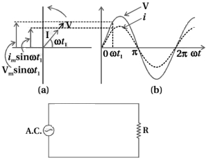
Explain the representation of $AC$ current and voltage by rotating vectors.
Solution
(N/A) The $AC$ current through a resistor is in phase with the voltage. However,this is not the case for an inductor,a capacitor,or a combination of these circuit elements.
To show the phase relationship between voltage and current in an $AC$ circuit,it is convenient to analyze the circuit using the concept of phasors.
$A$ phasor is a vector that rotates about the origin with an angular speed $\omega$,as shown in the figure.
The vertical components of the phasors $V$ and $I$ are $V_{m} \sin \omega t$ and $I_{m} \sin \omega t$,where $V_{m}$ and $I_{m}$ represent the peak values of the oscillating quantities.
Figure $(a)$ shows the voltage and current phasors and their relationship at time $t_{1}$ for a resistor connected to an $AC$ source.
The projections of the $V$ and $I$ phasors on the vertical axis,$V_{m} \sin \omega t_{1}$ and $I_{m} \sin \omega t_{1}$,represent the instantaneous values of voltage and current.
Figure $(b)$ shows the corresponding sinusoidal waveforms generated by these rotating vectors with frequency $\omega$.
For a resistor,the phasors $V$ and $I$ are in the same direction,which means the phase angle between the voltage and the current is zero.
0 likes
View Solution61
Medium
Obtain an equation for the current when an $AC$ voltage is applied to an inductor and draw a graph of $V$ and $I$ versus time.
Solution
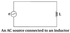
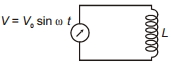
(N/A) The figure shows an $AC$ source connected to an inductor of inductance $L$. The inductor has negligible resistance,so the circuit is a purely inductive $AC$ circuit.
Let the voltage across the source be $V = V_m \sin \omega t$.
Using Kirchhoff's loop rule,$V - L \frac{dI}{dt} = 0$,where $-L \frac{dI}{dt}$ is the self-induced $emf$.
Therefore,$V = L \frac{dI}{dt}$,which implies $\frac{dI}{dt} = \frac{V}{L}$.
Substituting $V = V_m \sin \omega t$,we get $\frac{dI}{dt} = \frac{V_m}{L} \sin \omega t$.
Integrating with respect to time $t$,we get $I = \int \frac{V_m}{L} \sin \omega t \, dt = -\frac{V_m}{L \omega} \cos \omega t + C$.
Since the current is purely sinusoidal,the integration constant $C$ must be zero.
Thus,$I = -\frac{V_m}{L \omega} \cos \omega t = \frac{V_m}{\omega L} \sin(\omega t - \frac{\pi}{2})$.
Defining $I_m = \frac{V_m}{\omega L}$,we have $I = I_m \sin(\omega t - \frac{\pi}{2})$.
This shows that the current lags behind the voltage by a phase angle of $\frac{\pi}{2}$.
0 likes
View Solution62
Medium
Discuss the power in an $AC$ circuit containing only an inductor.
Solution
(N/A) In an $AC$ circuit containing only an inductor,the current lags behind the voltage by a phase angle of $\frac{\pi}{2}$ radians,which corresponds to a time delay of one-fourth of a period,$\frac{T}{4} = \frac{\pi/2}{\omega}$.
The instantaneous voltage is $V = V_m \sin(\omega t)$ and the instantaneous current is $I = I_m \sin(\omega t - \frac{\pi}{2}) = -I_m \cos(\omega t)$.
The instantaneous power $P_L$ supplied to the inductor is given by:
$P_L = IV = [I_m \sin(\omega t - \frac{\pi}{2})] \times [V_m \sin(\omega t)]$
$P_L = -I_m V_m \cos(\omega t) \sin(\omega t)$
Using the identity $\sin(2\theta) = 2\sin\theta \cos\theta$,we get:
$P_L = -\frac{I_m V_m}{2} \sin(2\omega t)$
The average power $\langle P_L \rangle$ over a complete cycle is the average of the instantaneous power over time $T$:
$\langle P_L \rangle = \left\langle -\frac{I_m V_m}{2} \sin(2\omega t) \right\rangle$
Since the average value of $\sin(2\omega t)$ over a complete cycle is zero,we have:
$\langle P_L \rangle = -\frac{I_m V_m}{2} \times 0 = 0$
Thus,the average power supplied to a pure inductor over one complete cycle is zero.
0 likes
View Solution63
Medium
Obtain the formula for current when an $AC$ voltage is applied to a capacitor and draw the graphs of $V$ and $I$ versus $\omega t$.
Solution
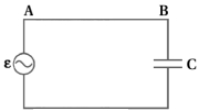
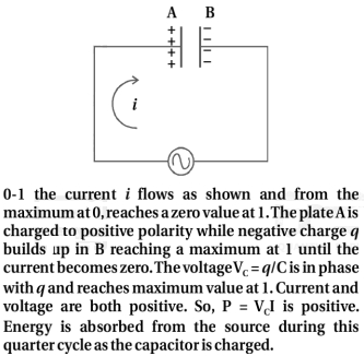
(N/A) pure capacitor connected in an $AC$ circuit is shown in the figure. The capacitor is connected to an $AC$ voltage source $V = V_{m} \sin \omega t$.
When a capacitor is connected to a voltage source in a $DC$ circuit,current flows only for the short time required to charge the capacitor.
As charge accumulates on the capacitor plates,the voltage across them increases,opposing the current.
When the capacitor is fully charged,the current in the circuit falls to zero.
When the capacitor is connected to an $AC$ source,it limits or regulates the current but does not completely prevent the flow of charge.
The capacitor is alternately charged and discharged as the current reverses each half cycle.
Let $q$ be the charge on the capacitor at any time $t$. The instantaneous voltage $V$ across the capacitor is $V = \frac{q}{C}$,where $C$ is the capacitance.
From Kirchhoff's loop rule:
$V_{m} \sin \omega t - \frac{q}{C} = 0$
$\therefore V_{m} \sin \omega t = \frac{q}{C}$
$\therefore q = C V_{m} \sin \omega t$
Now,the current $I = \frac{dq}{dt}$:
$I = \frac{d}{dt} [C V_{m} \sin \omega t]$
$I = C V_{m} \omega \cos \omega t$
$I = \frac{V_{m}}{1 / \omega C} \cos \omega t$
Using $\cos \omega t = \sin \left(\omega t + \frac{\pi}{2}\right)$ and defining $I_{m} = \frac{V_{m}}{1 / \omega C} = \omega C V_{m}$:
$I = I_{m} \sin \left(\omega t + \frac{\pi}{2}\right)$
This shows that the current leads the voltage by a phase angle of $\frac{\pi}{2}$.
0 likes
View Solution64
Easy
Discuss power in an $AC$ circuit containing only a capacitor.
Solution
(N/A) The instantaneous power supplied to the capacitor is given by:
$p = v \cdot i$
Let the voltage across the capacitor be $v = V_m \sin(\omega t)$.
The current in a purely capacitive circuit leads the voltage by $\pi/2$,so $i = I_m \sin(\omega t + \pi/2) = I_m \cos(\omega t)$.
Thus,the instantaneous power is:
$p = (V_m \sin(\omega t)) \cdot (I_m \cos(\omega t))$
$p = V_m I_m \sin(\omega t) \cos(\omega t)$
Using the identity $\sin(2\theta) = 2 \sin \theta \cos \theta$,we get:
$p = \frac{V_m I_m}{2} \sin(2\omega t)$
The average power $P$ over a complete cycle is the average of the instantaneous power over one period $T = 2\pi/\omega$:
$P = \langle p \rangle = \frac{V_m I_m}{2} \langle \sin(2\omega t) \rangle$
Since the average value of $\sin(2\omega t)$ over a complete cycle is zero,the average power dissipated in a purely capacitive circuit is:
$P = 0$
This indicates that a capacitor does not consume any real power in an $AC$ circuit; it only stores and releases energy.
0 likes
View Solution65
EasyMCQ
What is the phase difference between voltage $V$ and current $I$ in an $AC$ circuit containing only a capacitor?
A
$0$
B
$\pi/2$
C
$\pi$
D
$\pi/4$
Solution
(B) In an $AC$ circuit containing only a capacitor,the current $I$ leads the voltage $V$ by a phase angle of $\pi/2$ radians (or $90^{\circ}$).
This means the voltage $V$ lags behind the current $I$ by $\pi/2$.
Therefore,the phase difference between voltage $V$ and current $I$ is $\pi/2$.
This means the voltage $V$ lags behind the current $I$ by $\pi/2$.
Therefore,the phase difference between voltage $V$ and current $I$ is $\pi/2$.
0 likes
View Solution66
Medium
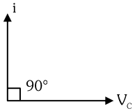
$(i)$ What is the angle between the phasor of $V_R$ and $I$?
$(ii)$ The voltage phasor $V_C$ is ...... of the current phasor $I$. (Fill in the blank)
$(ii)$ The voltage phasor $V_C$ is ...... of the current phasor $I$. (Fill in the blank)
Solution
(N/A) $(i)$ In a purely resistive circuit,the voltage $V_R$ and the current $I$ are in the same phase. Therefore,the phase angle between the phasor of $V_R$ and $I$ is $0^{\circ}$.
$(ii)$ In a purely capacitive circuit,the voltage $V_C$ lags behind the current $I$ by a phase angle of $90^{\circ}$ or $\pi/2$ radians. Thus,the voltage phasor $V_C$ is $90^{\circ}$ behind the current phasor $I$.
$(ii)$ In a purely capacitive circuit,the voltage $V_C$ lags behind the current $I$ by a phase angle of $90^{\circ}$ or $\pi/2$ radians. Thus,the voltage phasor $V_C$ is $90^{\circ}$ behind the current phasor $I$.
0 likes
View Solution67
Medium
What is a resistive circuit? Write the formula for the power consumed in it.
Solution
(N/A) resistive circuit is an electrical circuit that contains only a resistor (or a combination of resistors) connected to an $AC$ source,where the current and voltage are in the same phase.
In a purely resistive circuit,the phase difference between voltage and current is $\phi = 0^\circ$.
The instantaneous power consumed in the circuit is given by $P = VI \cos \phi$.
Since $\cos 0^\circ = 1$,the average power consumed in a resistive circuit is $P_{avg} = V_{rms} I_{rms} = I_{rms}^2 R = \frac{V_{rms}^2}{R}$,where $V_{rms}$ is the root-mean-square voltage and $I_{rms}$ is the root-mean-square current.
0 likes
View Solution68
MediumMCQ
In which circuit is the average power consumed maximum?
A
Purely inductive circuit
B
Purely capacitive circuit
C
Purely resistive circuit
D
$LC$ circuit
Solution
(C) The average power consumed in an $AC$ circuit is given by the formula $P_{avg} = V_{rms} I_{rms} \cos \phi$,where $\cos \phi$ is the power factor.
For a purely resistive circuit,the phase difference $\phi$ between voltage and current is $0^\circ$. Therefore,the power factor $\cos \phi = \cos 0^\circ = 1$.
For purely inductive and purely capacitive circuits,the phase difference $\phi$ is $90^\circ$,so $\cos \phi = \cos 90^\circ = 0$,resulting in zero average power consumption.
For an $LC$ circuit,the average power is also zero because the current and voltage are $90^\circ$ out of phase.
Thus,the average power consumed is maximum in a purely resistive circuit.
0 likes
View Solution69
Medium
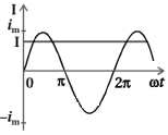
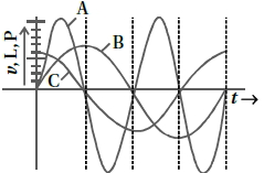
$A$ device $'X'$ is connected to an a.c. source. The variation of voltage,current,and power in one complete cycle is shown in the figure.
$(a)$ Which curve shows power consumption over a full cycle?
$(b)$ What is the average power consumption over a cycle?
$(c)$ Identify the device $'X'$.
$(a)$ Which curve shows power consumption over a full cycle?
$(b)$ What is the average power consumption over a cycle?
$(c)$ Identify the device $'X'$.
Solution
(A) We know that power $P = VI$. The curve of power will have a maximum amplitude equal to the product of the amplitudes of the voltage and current curves. Therefore,the curve is represented by $A$.
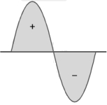
$(b)$ As shown by the shaded area in the diagram,the full cycle of the graph consists of one positive and one negative symmetrical area.
Hence,the average power over a cycle is zero.
$(c)$ Since the average power is zero,the device $'X'$ must be a pure inductor $(L)$,a pure capacitor $(C)$,or a series combination of $L$ and $C$ (i.e.,a purely reactive circuit).
0 likes
View Solution70
Easy
Explain why the reactance provided by a capacitor to an alternating current decreases with increasing frequency.
Solution
(N/A) capacitor does not allow the flow of direct current $(DC)$ through it because the resistance across the gap is infinite.
When an alternating current $(AC)$ is applied across the capacitor plates,the plates are alternately charged and discharged.
The current through the capacitor is a result of this changing voltage (or charge).
Thus,a capacitor will pass more current if the voltage changes at a faster rate,which means if the frequency of the supply is higher.
This implies that the reactance offered by a capacitor is less with increasing frequency.
Mathematically,the capacitive reactance is given by $X_{C} = \frac{1}{2 \pi \nu C}$,where $\nu$ is the frequency and $C$ is the capacitance. As $\nu$ increases,$X_{C}$ decreases.
0 likes
View Solution71
Easy
Explain why the reactance offered by an inductor increases with increasing frequency of an alternating voltage.
Solution
(N/A) An inductor opposes the flow of current through it by developing a back emf according to Lenz's law. The induced voltage has a polarity that opposes the change in current.
The induced emf is given by $\varepsilon = -L \frac{di}{dt}$. For an alternating current $i = I_0 \sin(\omega t)$,the induced emf is $\varepsilon = -L \frac{d}{dt}(I_0 \sin(\omega t)) = -L I_0 \omega \cos(\omega t)$.
The magnitude of the induced voltage is proportional to the angular frequency $\omega = 2 \pi f$. Since the reactance $X_L$ is defined as the ratio of the peak voltage to the peak current,we have $X_L = \frac{V_0}{I_0} = \omega L = 2 \pi f L$.
As the frequency $f$ increases,the rate of change of current $\frac{di}{dt}$ increases,leading to a higher induced back emf. Consequently,the inductor offers greater opposition (reactance) to the flow of current at higher frequencies.
0 likes
View Solution72
MediumMCQ
$A$ $40 \, \mu F$ capacitor is connected to a $200 \, V, 50 \, Hz$ $AC$ supply. The rms value of the current in the circuit is nearly $....... A$.
A
$25.1$
B
$1.7$
C
$2.05$
D
$2.5$
Solution
(D) Given: Capacitance $C = 40 \, \mu F = 40 \times 10^{-6} \, F$, Voltage $V_{rms} = 200 \, V$, Frequency $f = 50 \, Hz$.
The capacitive reactance is given by $X_C = \frac{1}{\omega C} = \frac{1}{2 \pi f C}$.
The rms current is given by $I_{rms} = \frac{V_{rms}}{X_C} = V_{rms} \times 2 \pi f C$.
Substituting the values:
$I_{rms} = 200 \times 2 \times 3.1416 \times 50 \times 40 \times 10^{-6}$.
$I_{rms} = 200 \times 314.16 \times 40 \times 10^{-6} = 2.513 \, A$.
Rounding to the nearest value, we get $I_{rms} \approx 2.5 \, A$.
0 likes
View Solution73
MediumMCQ
What happens to the inductive reactance and the current in a purely inductive circuit if the frequency is halved?
A
Both,inductive reactance and current will be halved.
B
Inductive reactance will be halved and current will be doubled.
C
Inductive reactance will be doubled and current will be halved.
D
Both,inductive reactance and current will be doubled.
Solution
(B) The inductive reactance is given by $X_{L} = \omega L = 2\pi f L$.
Since $X_{L} \propto f$,if the frequency $f$ is halved,the inductive reactance $X_{L}$ will also be halved.
The current in a purely inductive circuit is given by $I = \frac{V}{X_{L}}$.
Since $I \propto \frac{1}{X_{L}}$,if the inductive reactance $X_{L}$ is halved,the current $I$ will be doubled.
Therefore,the inductive reactance is halved and the current is doubled.
0 likes
View Solution74
MediumMCQ
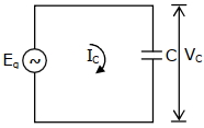
In a circuit consisting of a capacitance and a generator with alternating emf $E_{g}=E_{g0} \sin \omega t$,$V_{C}$ and $I_{C}$ are the voltage and current. The correct phasor diagram for such a circuit is:
A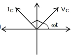
B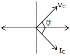
C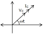
D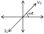
Solution
(A) In a purely capacitive circuit,the current $I_{C}$ leads the voltage $V_{C}$ across the capacitor by a phase angle of $\frac{\pi}{2}$ radians $(90^{\circ})$.
Mathematically,if $V_{C} = V_{0} \sin \omega t$,then $I_{C} = I_{0} \sin(\omega t + \frac{\pi}{2})$.
This means that the phasor representing current $I_{C}$ is rotated $90^{\circ}$ counter-clockwise relative to the phasor representing voltage $V_{C}$.
Looking at the provided options,the correct phasor diagram is the one where $I_{C}$ is $90^{\circ}$ ahead of $V_{C}$ in the counter-clockwise direction.
0 likes
View Solution75
MediumMCQ
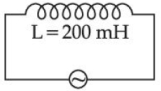
As shown in the figure,an inductor of inductance $L = 200 \, mH$ is connected to an $AC$ source of emf $220 \, V$ and frequency $f = 50 \, Hz$. The peak value of current is given by $\frac{\sqrt{a}}{\pi} \, A$. The value of $a$ is..........
A
$282$
B
$242$
C
$247$
D
$867$
Solution
(B) Given: Inductance $L = 200 \, mH = 0.2 \, H$,$V_{rms} = 220 \, V$,$f = 50 \, Hz$.
The inductive reactance $X_L$ is given by:
$X_L = 2 \pi f L = 2 \pi \times 50 \times 0.2 = 20 \pi \, \Omega$.
The peak voltage $V_0$ is:
$V_0 = V_{rms} \sqrt{2} = 220 \sqrt{2} \, V$.
The peak current $i_0$ is:
$i_0 = \frac{V_0}{X_L} = \frac{220 \sqrt{2}}{20 \pi} = \frac{11 \sqrt{2}}{\pi} \, A$.
We can rewrite this as:
$i_0 = \frac{\sqrt{11^2 \times 2}}{\pi} = \frac{\sqrt{121 \times 2}}{\pi} = \frac{\sqrt{242}}{\pi} \, A$.
Comparing this with the given expression $\frac{\sqrt{a}}{\pi} \, A$,we get:
$a = 242$.
0 likes
View Solution76
MediumMCQ
If wattless current flows in the $AC$ circuit, then the circuit is
A
Purely Resistive circuit
B
Purely Inductive circuit
C
$LCR$ series circuit
D
$RC$ series circuit only
Solution
(B) In an $AC$ circuit, the average power consumed is given by $P = V_{rms} I_{rms} \cos \phi$, where $\phi$ is the phase difference between voltage and current.
A wattless current is a current that flows in a circuit without consuming any average power.
For the power to be zero, the power factor $\cos \phi$ must be zero, which implies $\phi = \frac{\pi}{2}$ (or $90^{\circ}$).
This condition occurs in a purely inductive circuit or a purely capacitive circuit, where the phase difference between voltage and current is exactly $\frac{\pi}{2}$.
Among the given options, a purely inductive circuit satisfies this condition.
0 likes
View Solution77
MediumMCQ
The rms value of conduction current in a parallel plate capacitor is $6.9\,\mu A$. The capacity of this capacitor,if it is connected to a $230\,V$ $AC$ supply with an angular frequency of $600\,rad/s$,will be $....\,pF$.
A
$5$
B
$50$
C
$100$
D
$200$
Solution
(B) The current in a capacitor is given by the formula $I = \frac{V}{X_C}$,where $X_C = \frac{1}{\omega C}$ is the capacitive reactance.
Substituting $X_C$,we get $I = V \omega C$.
Rearranging for capacitance $C$,we have $C = \frac{I}{V \omega}$.
Given values are $I = 6.9 \times 10^{-6}\,A$,$V = 230\,V$,and $\omega = 600\,rad/s$.
Substituting these values: $C = \frac{6.9 \times 10^{-6}}{230 \times 600}$.
$C = \frac{6.9 \times 10^{-6}}{138000} = 0.05 \times 10^{-9}\,F$.
$C = 50 \times 10^{-12}\,F = 50\,pF$.
0 likes
View Solution78
MediumMCQ
The equation of current in a purely inductive circuit is $i = 5 \sin (49 \pi t - 30^{\circ})$. If the inductance is $30 \, mH$,then the equation for the voltage across the inductor will be. (Let $\pi = \frac{22}{7}$)
A
$1.47 \sin (49 \pi t - 30^{\circ})$
B
$1.47 \sin (49 \pi t + 60^{\circ})$
C
$23.1 \sin (49 \pi t - 30^{\circ})$
D
$23.1 \sin (49 \pi t + 60^{\circ})$
Solution
(D) The given current equation is $i = i_0 \sin (\omega t - 30^{\circ})$,where $i_0 = 5 \, A$ and $\omega = 49 \pi \, rad/s$.
In a purely inductive circuit,the inductive reactance is $X_L = \omega L$.
Given $L = 30 \, mH = 30 \times 10^{-3} \, H$.
$X_L = (49 \times \frac{22}{7}) \times 30 \times 10^{-3} = (7 \times 22) \times 30 \times 10^{-3} = 154 \times 30 \times 10^{-3} = 4.62 \, \Omega$.
The peak voltage is $v_0 = i_0 X_L = 5 \times 4.62 = 23.1 \, V$.
In a purely inductive circuit,the voltage leads the current by $90^{\circ}$.
Therefore,the phase of the voltage is $(-30^{\circ} + 90^{\circ}) = +60^{\circ}$.
The voltage equation is $v = v_0 \sin (\omega t + 60^{\circ}) = 23.1 \sin (49 \pi t + 60^{\circ})$.
0 likes
View Solution79
DifficultMCQ
An alternating $emf$ $E = 440 \sin(100 \pi t)$ is applied to a circuit containing an inductance of $\frac{\sqrt{2}}{\pi} \text{ H}$. If an $AC$ ammeter is connected in the circuit,its reading will be $....... \text{ A}$.
A
$4.4$
B
$1.55$
C
$2.2$
D
$3.1$
Solution
(C) Given: $E = 440 \sin(100 \pi t)$ and $L = \frac{\sqrt{2}}{\pi} \text{ H}$.
Comparing with $E = E_0 \sin(\omega t)$,we get $E_0 = 440 \text{ V}$ and $\omega = 100 \pi \text{ rad/s}$.
The inductive reactance $X_L$ is given by $X_L = \omega L = (100 \pi) \times \left( \frac{\sqrt{2}}{\pi} \right) = 100 \sqrt{2} \, \Omega$.
The peak current $I_0$ is $I_0 = \frac{E_0}{X_L} = \frac{440}{100 \sqrt{2}} = \frac{4.4}{\sqrt{2}} \text{ A}$.
An $AC$ ammeter measures the $RMS$ value of the current.
$I_{rms} = \frac{I_0}{\sqrt{2}} = \frac{4.4 / \sqrt{2}}{\sqrt{2}} = \frac{4.4}{2} = 2.2 \text{ A}$.
Thus,the reading of the ammeter is $2.2 \text{ A}$.
0 likes
View Solution80
EasyMCQ
There is no resistance in the inductive circuit. Kirchhoff's voltage law for the circuit is
A
$V + L \frac{di}{dt} = 0$
B
$V = L \frac{di}{dt}$
C
$V - L^2 \frac{di}{dt} = 0$
D
None of these
Solution
(B) According to Kirchhoff's voltage law $(KVL)$,the algebraic sum of potential differences around any closed loop is zero.
For an inductive circuit with no resistance,the potential difference across the source $V$ and the induced electromotive force $(EMF)$ across the inductor $L$ must balance each other.
The induced $EMF$ across an inductor is given by $\varepsilon = -L \frac{di}{dt}$.
Applying $KVL$ to the loop:
$V + \varepsilon = 0$
$V + (-L \frac{di}{dt}) = 0$
$V - L \frac{di}{dt} = 0$
$V = L \frac{di}{dt}$
0 likes
View Solution81
EasyMCQ
$A$ sinusoidal supply of frequency $10 \,Hz$ and $r.m.s.$ voltage $12 \,V$ is connected to a $2.1 \,\mu F$ capacitor. What is the $r.m.s.$ value of current in $mA$?
A
$5.5$
B
$20$
C
$26$
D
$1.6$
Solution
(D) Given: Frequency $f = 10 \,Hz$,$r.m.s.$ voltage $V_{rms} = 12 \,V$,and capacitance $C = 2.1 \,\mu F = 2.1 \times 10^{-6} \,F$.
The capacitive reactance $X_c$ is given by $X_c = \frac{1}{\omega C} = \frac{1}{2 \pi f C}$.
Substituting the values:
$X_c = \frac{1}{2 \times 3.14159 \times 10 \times 2.1 \times 10^{-6}} \approx \frac{1}{1.319 \times 10^{-4}} \approx 7580 \,\Omega$.
The $r.m.s.$ current $I_{rms}$ is given by $I_{rms} = \frac{V_{rms}}{X_c}$.
$I_{rms} = \frac{12}{7580} \approx 0.001583 \,A$.
Converting to $mA$:
$I_{rms} \approx 0.001583 \times 1000 \,mA \approx 1.583 \,mA \approx 1.6 \,mA$.
0 likes
View Solution82
EasyMCQ
An $a.c.$ of frequency $f$ is flowing in a circuit containing only an ideal choke coil of inductance $L$. If $V_0$ and $i_0$ represent peak values of the voltage and the current respectively,the average power given by the source to the choke coil is equal to
A
$\frac{1}{2} i_0 V_0$
B
$\frac{1}{2} i_0^2(2 \pi f L)$
C
Zero
D
$\frac{1}{2} V_0(2 \pi f L)$
Solution
(C) In an ideal choke coil (pure inductor),the current lags behind the voltage by a phase angle of $\phi = 90^\circ$ or $\frac{\pi}{2} \text{ radians}$.
The average power $P$ in an $a.c.$ circuit is given by the formula:
$P = V_{rms} I_{rms} \cos \phi$
Since the choke coil is ideal,its resistance is zero,making it a purely inductive circuit. For a purely inductive circuit,the power factor $\cos \phi = \cos 90^\circ = 0$.
Substituting this into the power formula:
$P = V_{rms} I_{rms} \times 0 = 0$.
Therefore,the average power dissipated by an ideal choke coil is zero.
0 likes
View Solution83
EasyMCQ
An alternating voltage source $V = 260 \sin(628t)$ is connected across a pure inductor of $5\,mH$. Inductive reactance in the circuit is $......... \Omega$.
A
$3.14$
B
$6.28$
C
$0.5$
D
$3.14$
Solution
(A) The given alternating voltage equation is $V = V_m \sin(\omega t)$.
Comparing this with $V = 260 \sin(628t)$,we get the angular frequency $\omega = 628\,rad/s$.
The inductance of the inductor is $L = 5\,mH = 5 \times 10^{-3}\,H$.
The inductive reactance $X_L$ is given by the formula $X_L = \omega L$.
Substituting the values,$X_L = 628 \times 5 \times 10^{-3} = 3140 \times 10^{-3} = 3.14\,\Omega$.
Therefore,the inductive reactance is $3.14\,\Omega$.
0 likes
View Solution84
EasyMCQ
Given below are two statements:
Statement-$I$: In an $AC$ circuit,the current through a capacitor leads the voltage across it.
Statement-$II$: In $AC$ circuits containing pure capacitance only,the phase difference between the current and the voltage is $\pi$.
In the light of the above statements,choose the most appropriate answer from the options given below:
A
Both statement-$I$ and statement-$II$ are correct.
B
Both statement-$I$ and statement-$II$ are incorrect.
C
Statement-$I$ is correct but statement-$II$ is incorrect.
D
Statement-$I$ is incorrect but statement-$II$ is correct.
Solution
(C) Statement-$I$: In a purely capacitive $AC$ circuit,the current leads the voltage by a phase angle of $\pi/2$ radians $(90^{\circ})$. Thus,statement-$I$ is correct.
Statement-$II$: In a purely capacitive $AC$ circuit,the phase difference between the current and the voltage is $\pi/2$,not $\pi$. Thus,statement-$II$ is incorrect.
Therefore,statement-$I$ is correct but statement-$II$ is incorrect.
Statement-$II$: In a purely capacitive $AC$ circuit,the phase difference between the current and the voltage is $\pi/2$,not $\pi$. Thus,statement-$II$ is incorrect.
Therefore,statement-$I$ is correct but statement-$II$ is incorrect.
0 likes
View Solution85
MediumMCQ
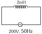
An inductor of inductance $2 \, mH$ is connected to a $220 \, V, 50 \, Hz$ $AC$ source. Let the inductive reactance in the circuit be $X_1$. If a $220 \, V$ $DC$ source replaces the $AC$ source in the circuit,then the inductive reactance in the circuit is $X_2$. $X_1$ and $X_2$ respectively are:
A
$6.28 \, \Omega$,zero
B
$6.28 \, \Omega$,infinity
C
$0.628 \, \Omega$,zero
D
$0.628 \, \Omega$,infinity
Solution
(C) For an $AC$ source,the inductive reactance is given by $X_L = \omega L = 2 \pi f L$.
Given $L = 2 \, mH = 2 \times 10^{-3} \, H$ and $f = 50 \, Hz$.
$X_1 = 2 \times \pi \times 50 \times 2 \times 10^{-3} = 100 \pi \times 2 \times 10^{-3} = 0.2 \pi \, \Omega$.
Using $\pi \approx 3.14$,we get $X_1 = 0.2 \times 3.14 = 0.628 \, \Omega$.
For a $DC$ source,the frequency $f = 0$,so the angular frequency $\omega = 2 \pi f = 0$.
The inductive reactance $X_2 = \omega L = 0 \times L = 0 \, \Omega$.
Thus,$X_1 = 0.628 \, \Omega$ and $X_2 = 0$.
0 likes
View Solution86
MediumMCQ
$A$ capacitor of capacitance $150.0\,\mu F$ is connected to an alternating source of $emf$ given by $E = 36 \sin(120 \pi t) \, V$. The maximum value of current in the circuit is approximately equal to $...... \, A$.
A
$2$
B
$\frac{1}{\sqrt{2}}$
C
$\sqrt{2}$
D
$2 \sqrt{2}$
Solution
(A) The given $emf$ is $E = E_0 \sin(\omega t)$,where $E_0 = 36 \, V$ and $\omega = 120 \pi \, rad/s$.
The capacitive reactance is $X_C = \frac{1}{\omega C}$.
The maximum current $I_0$ is given by $I_0 = \frac{E_0}{X_C} = E_0 \omega C$.
Substituting the values: $I_0 = 36 \times 120 \pi \times 150 \times 10^{-6} \, A$.
$I_0 = 36 \times 120 \times 3.1416 \times 150 \times 10^{-6} \, A$.
$I_0 = 648000 \times 3.1416 \times 10^{-6} \, A \approx 2.035 \, A$.
Therefore,the maximum current is approximately $2 \, A$.
0 likes
View Solution87
MediumMCQ
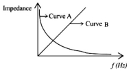
As per the given graph,choose the correct representation for curve $A$ and curve $B$. Where $X_{C} =$ reactance of a pure capacitive circuit connected to an $A.C.$ source,$X_{L} =$ reactance of a pure inductive circuit connected to an $A.C.$ source,$R =$ resistance of a pure resistive circuit connected to an $A.C.$ source,and $Z =$ impedance of the $LCR$ series circuit.
A
$A = X_{C}, B = X_{L}$
B
$A = X_{L}, B = X_{C}$
C
$A = R, B = X_{L}$
D
$A = X_{C}, B = R$
Solution
(A) The reactance of a pure capacitive circuit is given by $X_{C} = \frac{1}{\omega C} = \frac{1}{2 \pi f C}$.
This implies $X_{C} \propto \frac{1}{f}$,which represents a rectangular hyperbola. Thus,curve $A$ corresponds to $X_{C}$.
The reactance of a pure inductive circuit is given by $X_{L} = \omega L = 2 \pi f L$.
This implies $X_{L} \propto f$,which represents a straight line passing through the origin. Thus,curve $B$ corresponds to $X_{L}$.
Therefore,the correct representation is $A = X_{C}$ and $B = X_{L}$.
0 likes
View Solution88
MediumMCQ
An $AC$ source is connected to a capacitor $C$. Due to a decrease in its operating frequency:
A
Capacitive reactance remains constant.
B
Capacitive reactance decreases.
C
Displacement current increases.
D
Displacement current decreases.
Solution
(D) The capacitive reactance is given by $X_C = \frac{1}{\omega C} = \frac{1}{2\pi f C}$.
As the frequency $f$ decreases,the capacitive reactance $X_C$ increases.
The displacement current $i_D$ in a capacitor is equal to the conduction current $i_C$,which is given by $i_D = i_C = \frac{V}{X_C} = V \cdot (2\pi f C)$.
Since $i_D \propto f$,a decrease in frequency $f$ leads to a decrease in the displacement current $i_D$.
0 likes
View Solution89
DifficultMCQ
An alternating voltage $V(t) = 220 \sin(100 \pi t)$ volt is applied to a purely resistive load of $50 \ \Omega$. The time taken for the current to rise from half of the peak value to the peak value is: (in $ms$)
A
$5$
B
$3.3$
C
$7.2$
D
$2.2$
Solution
(B) The given voltage is $V(t) = 220 \sin(100 \pi t)$. Since the load is purely resistive,the current $I(t)$ is in phase with the voltage: $I(t) = I_0 \sin(100 \pi t)$,where $I_0 = V_0 / R = 220 / 50 = 4.4 \ A$.
We need the time taken for the current to rise from $I_0 / 2$ to $I_0$.
At $t_1$,$I(t_1) = I_0 \sin(100 \pi t_1) = I_0 / 2 \implies 100 \pi t_1 = \pi / 6 \implies t_1 = 1 / 600 \ s$.
At $t_2$,$I(t_2) = I_0 \sin(100 \pi t_2) = I_0 \implies 100 \pi t_2 = \pi / 2 \implies t_2 = 1 / 200 \ s$.
The time taken is $\Delta t = t_2 - t_1 = 1/200 - 1/600 = (3 - 1) / 600 = 2 / 600 = 1 / 300 \ s$.
$\Delta t = 0.00333 \ s = 3.33 \ ms$.
0 likes
View Solution90
DifficultMCQ
$A$ series $LCR$ circuit is subjected to an $AC$ signal of $200 \,V, 50 \,Hz$. If the voltage across the inductor $(L=10 \,mH)$ is $31.4 \,V$,then the current in this circuit is $\qquad$
A
$68 \,A$
B
$63 \,A$
C
$10 \,A$
D
$10 \,mA$
Solution
(C) The voltage across an inductor in an $AC$ circuit is given by $V_{L} = I X_{L}$,where $I$ is the current and $X_{L}$ is the inductive reactance.
The inductive reactance is defined as $X_{L} = \omega L = 2 \pi f L$.
Given values are $V_{L} = 31.4 \,V$,$L = 10 \,mH = 10 \times 10^{-3} \,H$,and $f = 50 \,Hz$.
Substituting these values into the formula:
$31.4 = I \times (2 \times 3.14 \times 50 \times 10 \times 10^{-3})$
$31.4 = I \times (314 \times 10 \times 10^{-3})$
$31.4 = I \times 3.14$
$I = \frac{31.4}{3.14} = 10 \,A$.
Therefore,the current in the circuit is $10 \,A$.
0 likes
View Solution91
DifficultMCQ
An $AC$ alternating $emf$ $E = 110 \sqrt{2} \sin(100t) \text{ V}$ is applied to a capacitor of $2 \mu F$. The $rms$ value of current in the circuit is $...... \text{ mA}$.
A
$22$
B
$20$
C
$25$
D
$30$
Solution
(A) Given: $C = 2 \mu F = 2 \times 10^{-6} \text{ F}$,$E = 110 \sqrt{2} \sin(100t) \text{ V}$.
Comparing with $E = E_0 \sin(\omega t)$,we get peak voltage $E_0 = 110 \sqrt{2} \text{ V}$ and angular frequency $\omega = 100 \text{ rad/s}$.
The capacitive reactance is $X_C = \frac{1}{\omega C} = \frac{1}{100 \times 2 \times 10^{-6}} = \frac{1}{2 \times 10^{-4}} = 5000 \Omega$.
The peak current is $I_0 = \frac{E_0}{X_C} = \frac{110 \sqrt{2}}{5000} \text{ A}$.
The $rms$ current is $I_{rms} = \frac{I_0}{\sqrt{2}} = \frac{110 \sqrt{2}}{5000 \sqrt{2}} = \frac{110}{5000} \text{ A}$.
$I_{rms} = \frac{11}{500} \text{ A} = 0.022 \text{ A}$.
Converting to $mA$,$I_{rms} = 0.022 \times 1000 \text{ mA} = 22 \text{ mA}$.
0 likes
View Solution92
MediumMCQ
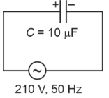
$A$ $10 \mu F$ capacitor is connected to a $210 \text{ V}, 50 \text{ Hz}$ source as shown in the figure. The peak current in the circuit is nearly $(\pi = 3.14)$ : (in $\text{ A}$)
A
$0.93$
B
$1.20$
C
$0.35$
D
$0.58$
Solution
$(A)$ The capacitive reactance $X_C$ is given by $X_C = \frac{1}{\omega C} = \frac{1}{2 \pi f C}$.
Substituting the given values: $X_C = \frac{1}{2 \times 3.14 \times 50 \times 10 \times 10^{-6}} = \frac{1}{3140 \times 10^{-6}} = \frac{1000}{3.14} \approx 318.47 \Omega$.
The $RMS$ voltage is $V_{\text{rms}} = 210 \text{ V}$.
The $RMS$ current is $I_{\text{rms}} = \frac{V_{\text{rms}}}{X_C} = \frac{210}{1000 / 3.14} = \frac{210 \times 3.14}{1000} = 0.6594 \text{ A}$.
The peak current $I_0$ is given by $I_0 = \sqrt{2} \times I_{\text{rms}}$.
$I_0 = 1.414 \times 0.6594 \approx 0.932 \text{ A}$.
Thus, the peak current is approximately $0.93 \text{ A}$.
0 likes
View Solution93
EasyMCQ
In an a.c. circuit with pure capacitance $C$ and a.c. source $E=E_0 \sin \omega t$,the equation of instantaneous current is given by
A
$I=E_0 \omega C \sin (\omega t)$
B
$I=E_0 \omega C \sin \left(\omega t+\frac{\pi}{2}\right)$
C
$I=\frac{E_0}{\omega C} \sin (\omega t)$
D
$I=\frac{E_0}{\omega C} \sin \left(\omega t+\frac{\pi}{2}\right)$
Solution
(B) The instantaneous voltage across a capacitor is given by $E = E_0 \sin \omega t$.
The charge $q$ on the capacitor is $q = CE = CE_0 \sin \omega t$.
The instantaneous current $I$ is the rate of change of charge: $I = \frac{dq}{dt} = \frac{d}{dt} (CE_0 \sin \omega t)$.
$I = CE_0 \omega \cos \omega t$.
Using the trigonometric identity $\cos \theta = \sin \left(\theta + \frac{\pi}{2}\right)$,we get:
$I = E_0 \omega C \sin \left(\omega t + \frac{\pi}{2}\right)$.
0 likes
View Solution94
MediumMCQ
An alternating voltage $v = 200 \sqrt{2} \sin(100 t)$ is connected to a $1 \mu F$ capacitor through an $A.C.$ ammeter. The reading of the ammeter shall be: (in $\text{ mA}$)
A
$10$
B
$20$
C
$40$
D
$80$
Solution
(B) The given alternating voltage is $v = 200 \sqrt{2} \sin(100 t)$.
Comparing this with the standard form $v = V_0 \sin(\omega t)$, we get the peak voltage $V_0 = 200 \sqrt{2} \text{ V}$ and angular frequency $\omega = 100 \text{ rad/s}$.
The capacitive reactance $X_C$ is given by $X_C = \frac{1}{\omega C}$.
Given $C = 1 \mu F = 10^{-6} \text{ F}$, we have $X_C = \frac{1}{100 \times 10^{-6}} = 10^4 \Omega$.
The peak current $I_0$ is $I_0 = \frac{V_0}{X_C} = \frac{200 \sqrt{2}}{10^4} = 2 \sqrt{2} \times 10^{-2} \text{ A}$.
The $A.C.$ ammeter measures the root mean square $(RMS)$ value of the current, $I_{rms}$.
$I_{rms} = \frac{I_0}{\sqrt{2}} = \frac{2 \sqrt{2} \times 10^{-2}}{\sqrt{2}} = 2 \times 10^{-2} \text{ A} = 20 \text{ mA}$.
0 likes
View Solution95
EasyMCQ
The inductive reactance of a coil is $R \ \Omega$. If the inductance of the coil is tripled and the frequency of the $A.C.$ supply is also tripled,then the new inductive reactance will be:
A
$\frac{R}{9}$
B
$\frac{R}{3}$
C
$3R$
D
$9R$
Solution
(D) The inductive reactance of a coil is given by the formula $X_{L} = 2 \pi f L$,where $f$ is the frequency and $L$ is the inductance.
Given that the initial inductive reactance is $X_{L1} = R = 2 \pi f L$.
If the inductance is tripled $(L' = 3L)$ and the frequency is tripled $(f' = 3f)$,the new inductive reactance $X_{L2}$ is:
$X_{L2} = 2 \pi f' L' = 2 \pi (3f) (3L) = 9 (2 \pi f L)$.
Substituting the initial value $R = 2 \pi f L$,we get:
$X_{L2} = 9R$.
0 likes
View Solution96
DifficultMCQ
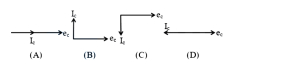
When an $A$.$C$. source is connected across a pure capacitor,the correct phase relation between current $(i_c)$ and voltage $(e_c)$ is shown in the figure.
A
$(A)$
B
$(B)$
C
$(C)$
D
$(D)$
Solution
(B) For a pure capacitor connected to an $A$.$C$. source,the voltage is given by $e_c = V_0 \sin(\omega t)$.
The charge on the capacitor is $q = C e_c = C V_0 \sin(\omega t)$.
The current in the circuit is $i_c = \frac{dq}{dt} = \frac{d}{dt} [C V_0 \sin(\omega t)] = \omega C V_0 \cos(\omega t) = \omega C V_0 \sin(\omega t + \frac{\pi}{2})$.
This shows that the current $i_c$ leads the voltage $e_c$ by a phase angle of $\frac{\pi}{2}$ radians.
In the given phasor diagrams,the vector representing $i_c$ should be $90^{\circ}$ ahead of the vector representing $e_c$ in the counter-clockwise direction.
Looking at the options,in diagram $(B)$,the current vector $i_c$ is $90^{\circ}$ ahead of the voltage vector $e_c$.
Therefore,the correct option is $(B)$.
0 likes
View Solution97
EasyMCQ
The same current is flowing in two alternating circuits. The first circuit contains only an inductor and the other contains only a capacitor. If the frequency of the alternating e.m.f. is increased,the values of current will
A
decrease in the first circuit and increase in the other.
B
increase in the first circuit and decrease in the other.
C
increase in both circuits.
D
decrease in both circuits.
Solution
(A) For an inductor,the inductive reactance is $X_L = 2\pi f L$. The current is given by $I = \frac{V}{X_L} = \frac{V}{2\pi f L}$.
Thus,$I \propto \frac{1}{f}$. As the frequency $f$ increases,the current $I$ decreases in the first circuit.
For a capacitor,the capacitive reactance is $X_C = \frac{1}{2\pi f C}$. The current is given by $I = \frac{V}{X_C} = V(2\pi f C)$.
Thus,$I \propto f$. As the frequency $f$ increases,the current $I$ increases in the second circuit.
0 likes
View Solution98
EasyMCQ
In the graphical representation of e.m.f. $e$ and current $i$ versus $\omega t$ for an a.c. circuit,both emf and current reach zero,minimum,and maximum values at the same time. The circuit element connected to the source will be
A
pure capacitor
B
combination of capacitor and inductor
C
pure resistor
D
pure inductor
Solution
(C) In an a.c. circuit,when the electromotive force $(e)$ and current $(i)$ reach their zero,minimum,and maximum values at the same time,it indicates that there is no phase difference between them.
This means the phase angle $\phi = 0$.
In a purely resistive circuit,the voltage and current are always in phase.
Therefore,the circuit element connected to the source must be a pure resistor.
This means the phase angle $\phi = 0$.
In a purely resistive circuit,the voltage and current are always in phase.
Therefore,the circuit element connected to the source must be a pure resistor.
0 likes
View Solution99
MediumMCQ
$A$ coil has an inductance of $2 \ H$. The ratio of its reactance,when it is connected first to an $AC$ source and then to a $DC$ source,is
A
Zero
B
$1$
C
Less than $1$
D
Infinity
Solution
(D) The inductive reactance of a coil in an $AC$ circuit is given by $X_L = \omega L = 2 \pi f L$,where $f$ is the frequency of the $AC$ source.
For an $AC$ source,the frequency $f > 0$,so the reactance $X_L$ has a finite non-zero value.
For a $DC$ source,the frequency $f = 0$. Therefore,the inductive reactance $X_L = 2 \pi (0) L = 0 \ \Omega$.
The ratio of the reactance in $AC$ to the reactance in $DC$ is $\frac{X_L(AC)}{X_L(DC)} = \frac{\omega L}{0} = \infty$.
Thus,the ratio is infinity.
0 likes
View Solution100
EasyMCQ
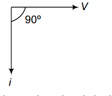
In a purely inductive circuit,the current is
A
in phase with the voltage
B
out of phase with the voltage
C
leads the voltage by $\pi / 2$
D
lags behind the voltage by $\pi / 2$
Solution
(D) In a purely inductive circuit,the voltage $V$ leads the current $i$ by a phase angle of $\pi / 2$ radians $(90^{\circ})$.
Conversely,this means the current $i$ lags behind the voltage $V$ by $\pi / 2$ radians.
This is represented by the phasor diagram where $V$ is along the positive x-axis and $i$ is along the negative y-axis.
Conversely,this means the current $i$ lags behind the voltage $V$ by $\pi / 2$ radians.
This is represented by the phasor diagram where $V$ is along the positive x-axis and $i$ is along the negative y-axis.
0 likes
View SolutionAlternating Current — Only Inductor, Only Capacitor and Only Resistor Circuit · Frequently Asked Questions
1Are these Alternating Current questions useful for JEE and NEET?
Yes. All questions in this section are mapped to JEE Main and NEET exam patterns. Previous year questions from JEE Main, NEET, GUJCET and state-level exams are included with full solutions.
2Can I switch to Hindi or Gujarati for these questions?
Yes. Use the language tabs in the hero section or the sidebar to view the same questions and solutions in English, Hindi or Gujarati.
3How do I generate a question paper from this subtopic?
Use the Vedclass Exam Paper Generator — select the chapter and subtopic, set difficulty, and generate Sets A, B, C, D automatically. First 3 chapters of every subject are free.
Vedclass Products
For Students
Vedclass Test Series
Mock tests in real JEE/NEET style with performance analysis. 5-day free trial.
Start Free TrialFor Teachers
Exam Paper Generator
Generate Set A/B/C/D papers from this chapter in 2 minutes. 3 chapters free.
Try FreeFor Institutes
Online Exam Module
Live online exams with unlimited students, 360° analytics & white-label branding.
See DemoFor Teachers & Institutes
Generate a Alternating Current Exam Paper in 2 Minutes
Select subtopic & difficulty — Sets A, B, C, D auto-generated with No Repeat logic.
First 3 chapters of every subject are free — no payment required.