
A English
Only Inductor, Only Capacitor and Only Resistor Circuit Questions in English
Class 12 Physics · Alternating Current · Only Inductor, Only Capacitor and Only Resistor Circuit
166+
Questions
English
Language
100%
With Solutions
Showing 50 of 166 questions in English
1
EasyMCQ
An $AC$ supply gives $30 \ V$ $rms$ which passes through a $10 \ \Omega$ resistance. The power dissipated in it is ...... $W$.
A
$90\sqrt{2}$
B
$90$
C
$45\sqrt{2}$
D
$45$
Solution
(B) The power dissipated in a resistor in an $AC$ circuit is given by the formula: $P = \frac{V_{rms}^2}{R}$.
Given:
$V_{rms} = 30 \ V$
$R = 10 \ \Omega$
Substituting the values into the formula:
$P = \frac{(30)^2}{10} = \frac{900}{10} = 90 \ W$.
Therefore,the power dissipated is $90 \ W$.
Given:
$V_{rms} = 30 \ V$
$R = 10 \ \Omega$
Substituting the values into the formula:
$P = \frac{(30)^2}{10} = \frac{900}{10} = 90 \ W$.
Therefore,the power dissipated is $90 \ W$.
0 likes
View Solution2
EasyMCQ
$A$ choke coil has
A
High inductance and low resistance
B
Low inductance and high resistance
C
High inductance and high resistance
D
Low inductance and low resistance
Solution
(A) choke coil is designed to have high inductance and low resistance.
Since an inductor is an ideal non-resistive device,it does not consume power in the form of heat,unlike a resistor.
By using a coil with high inductance $(L)$ and very low resistance $(R)$,we can control the current in an $AC$ circuit while minimizing power loss $(P = I^2 R)$.
Therefore,the correct option is $A$.
0 likes
View Solution3
EasyMCQ
$A$ choke coil is used to control:
A
$AC$
B
$DC$
C
Both $AC$ and $DC$
D
Neither $AC$ nor $DC$
Solution
(A) choke coil is an inductor with high inductance and negligible resistance. It is used to control current in $AC$ circuits.
In an $AC$ circuit,the inductive reactance is given by $X_L = \omega L = 2\pi f L$. Since $f > 0$,the choke coil offers significant impedance to the current.
In a $DC$ circuit,the frequency $f = 0$,so the inductive reactance $X_L = 0$. The coil acts as a simple wire with negligible resistance,failing to control the current effectively.
0 likes
View Solution4
EasyMCQ
An alternating e.m.f. is applied to a purely capacitive circuit. What is the phase relation between the e.m.f. and the current flowing in the circuit?
A
e.m.f. is ahead of current by $\pi / 2$
B
Current is ahead of e.m.f. by $\pi / 2$
C
Current lags behind e.m.f. by $\pi$
D
Current is ahead of e.m.f. by $\pi$
Solution
(B) For a purely capacitive circuit,the applied alternating e.m.f. is given by $e = e_0 \sin(\omega t)$.
In a capacitor,the current $i$ leads the voltage $e$ by a phase angle of $\pi / 2$.
Therefore,the expression for current is $i = i_0 \sin(\omega t + \pi / 2)$.
This indicates that the current is ahead of the e.m.f. by $\pi / 2$.
In a capacitor,the current $i$ leads the voltage $e$ by a phase angle of $\pi / 2$.
Therefore,the expression for current is $i = i_0 \sin(\omega t + \pi / 2)$.
This indicates that the current is ahead of the e.m.f. by $\pi / 2$.
0 likes
View Solution5
EasyMCQ
An $AC$ source is connected to a purely resistive circuit. Which of the following is true?
A
Current leads the voltage and both are in same phase
B
Current lags behind the voltage and both are in same phase
C
Current and voltage are in same phase
D
Any of the above may be true depending upon the value of resistance
Solution
(C) In a purely resistive $AC$ circuit, the voltage $V$ and current $I$ are given by $V = V_m \sin(\omega t)$ and $I = I_m \sin(\omega t)$.
Since the phase angle for both is $\omega t$, there is no phase difference between them.
Therefore, the current and voltage are in the same phase.
Since the phase angle for both is $\omega t$, there is no phase difference between them.
Therefore, the current and voltage are in the same phase.
0 likes
View Solution6
MediumMCQ
The average power dissipated in a pure inductor of inductance $L$ when an $AC$ current is passing through it,is (Inductance of the coil $L$ and current $I$)
A
$\frac{1}{2} L I^2$
B
$\frac{1}{4} L I^2$
C
$2 L I^2$
D
Zero
Solution
(D) In a pure inductive circuit,the current lags behind the voltage by a phase angle of $90^{\circ}$.
The formula for average power dissipated in an $AC$ circuit is given by $P_{\text{avg}} = V_{\text{rms}} I_{\text{rms}} \cos \phi$,where $\phi$ is the phase difference between voltage and current.
For a pure inductor,the phase difference $\phi = 90^{\circ}$.
Since $\cos 90^{\circ} = 0$,the average power dissipated is $P_{\text{avg}} = V_{\text{rms}} I_{\text{rms}} \cos 90^{\circ} = 0$.
Therefore,no power is dissipated in a pure inductor.
0 likes
View Solution7
EasyMCQ
In a circuit containing an inductance of zero resistance,the $e.m.f.$ of the applied $ac$ voltage leads the current by ......$^o$
A
$90$
B
$45$
C
$30$
D
$0$
Solution
(A) In a pure inductive circuit,the resistance $R = 0$.
For an inductor,the voltage $V$ leads the current $I$ by a phase angle of $\phi = 90^o$ or $\pi/2$ radians.
Therefore,the $e.m.f.$ of the applied $ac$ voltage leads the current by $90^o$.
For an inductor,the voltage $V$ leads the current $I$ by a phase angle of $\phi = 90^o$ or $\pi/2$ radians.
Therefore,the $e.m.f.$ of the applied $ac$ voltage leads the current by $90^o$.
0 likes
View Solution8
EasyMCQ
In a pure inductive circuit or in an $ac$ circuit containing inductance only,the current
A
Leads the e.m.f. by $90^{\circ}$
B
Lags behind the e.m.f. by $90^{\circ}$
C
Sometimes leads and sometimes lags behind the e.m.f.
D
Is in phase with the e.m.f.
Solution
(B) In a pure inductive circuit,the voltage $V$ across the inductor leads the current $I$ by a phase angle of $90^{\circ}$ (or $\frac{\pi}{2}$ radians).
Conversely,this means the current $I$ lags behind the electromotive force (e.m.f.) by $90^{\circ}$.
Mathematically,if $V = V_m \sin(\omega t)$,then $I = I_m \sin(\omega t - 90^{\circ})$.
Therefore,the current lags behind the e.m.f. by $90^{\circ}$.
Conversely,this means the current $I$ lags behind the electromotive force (e.m.f.) by $90^{\circ}$.
Mathematically,if $V = V_m \sin(\omega t)$,then $I = I_m \sin(\omega t - 90^{\circ})$.
Therefore,the current lags behind the e.m.f. by $90^{\circ}$.
0 likes
View Solution9
MediumMCQ
An alternating voltage $E = 200\sqrt{2} \sin(100t)$ is connected to a $1 \mu F$ capacitor through an $AC$ ammeter. The reading of the ammeter shall be $mA$.
A
$10$
B
$20$
C
$40$
D
$80$
Solution
(B) The given alternating voltage is $E = 200\sqrt{2} \sin(100t)$.
Comparing this with the standard equation $E = E_0 \sin(\omega t)$,we get the peak voltage $E_0 = 200\sqrt{2} \text{ V}$ and angular frequency $\omega = 100 \text{ rad/s}$.
The capacitance is $C = 1 \mu F = 1 \times 10^{-6} \text{ F}$.
The capacitive reactance is $X_C = \frac{1}{\omega C} = \frac{1}{100 \times 10^{-6}} = 10^4 \Omega$.
The $RMS$ voltage is $V_{rms} = \frac{E_0}{\sqrt{2}} = \frac{200\sqrt{2}}{\sqrt{2}} = 200 \text{ V}$.
The reading of the $AC$ ammeter is the $RMS$ current $I_{rms} = \frac{V_{rms}}{X_C} = \frac{200}{10^4} = 2 \times 10^{-2} \text{ A}$.
Converting to milliamperes,$I_{rms} = 2 \times 10^{-2} \times 10^3 \text{ mA} = 20 \text{ mA}$.
0 likes
View Solution10
EasyMCQ
The average power dissipation in a pure capacitance in an $AC$ circuit is
A
$1/2 C V^2$
B
$C V^2$
C
$1/4 C V^2$
D
Zero
Solution
(D) The average power dissipated in an $AC$ circuit is given by the formula $P = V_{rms} I_{rms} \cos \phi$,where $\phi$ is the phase difference between voltage and current.
In a pure capacitive circuit,the current leads the voltage by a phase angle of $\phi = 90^\circ$ (or $\pi/2$ radians).
The power factor is $\cos \phi = \cos 90^\circ = 0$.
Substituting this into the power formula,we get $P = V_{rms} I_{rms} \times 0 = 0$.
Therefore,the average power dissipation in a pure capacitor is zero.
0 likes
View Solution11
EasyMCQ
$A$ $120 \, V$ $AC$ source is connected across a pure inductor of inductance $0.70 \, H$. If the frequency of the source is $60 \, Hz$,the current passing through the inductor is: (in $, A$)
A
$4.55$
B
$0.355$
C
$0.455$
D
$3.55$
Solution
(C) The inductive reactance $X_L$ of the inductor is given by the formula $X_L = 2\pi f L$.
Given: $V = 120 \, V$,$f = 60 \, Hz$,and $L = 0.70 \, H$.
Substituting the values: $X_L = 2 \times 3.1416 \times 60 \times 0.70 \approx 263.89 \, \Omega$.
The current $I$ flowing through the inductor is given by $I = \frac{V}{X_L}$.
$I = \frac{120}{263.89} \approx 0.455 \, A$.
Therefore,the correct option is $C$.
0 likes
View Solution12
EasyMCQ
The reactance of a coil when used in the domestic $ac$ power supply $(220\, V, 50\, Hz)$ is $100\, \Omega$. The self-inductance of the coil is nearly........$H$.
A
$3.2$
B
$0.32$
C
$2.2$
D
$0.22$
Solution
(B) The inductive reactance $X_L$ is given by the formula $X_L = 2\pi \nu L$.
Given: $X_L = 100\, \Omega$ and frequency $\nu = 50\, Hz$.
Substituting the values into the formula:
$100 = 2 \times \pi \times 50 \times L$
$100 = 100 \times \pi \times L$
$L = \frac{1}{\pi} = \frac{1}{3.14} \approx 0.318\, H$.
Rounding to two decimal places, we get $L \approx 0.32\, H$.
Given: $X_L = 100\, \Omega$ and frequency $\nu = 50\, Hz$.
Substituting the values into the formula:
$100 = 2 \times \pi \times 50 \times L$
$100 = 100 \times \pi \times L$
$L = \frac{1}{\pi} = \frac{1}{3.14} \approx 0.318\, H$.
Rounding to two decimal places, we get $L \approx 0.32\, H$.
0 likes
View Solution13
EasyMCQ
The reactance of a $25\,\mu F$ capacitor at the ac frequency of $4000\, Hz$ is
A
$\frac{5}{\pi }\,\Omega$
B
$\sqrt{\frac{5}{\pi }}\,\Omega$
C
$10\,\Omega$
D
$\sqrt{10}\,\Omega$
Solution
(A) The capacitive reactance $X_C$ is given by the formula $X_C = \frac{1}{2\pi \nu C}$.
Given values are frequency $\nu = 4000\, Hz$ and capacitance $C = 25\,\mu F = 25 \times 10^{-6}\, F$.
Substituting these values into the formula:
$X_C = \frac{1}{2 \times \pi \times 4000 \times 25 \times 10^{-6}}$
$X_C = \frac{1}{2 \times \pi \times 10^5 \times 10^{-6}}$
$X_C = \frac{1}{2 \times \pi \times 10^{-1}}$
$X_C = \frac{1}{0.2 \times \pi} = \frac{10}{2\pi} = \frac{5}{\pi}\,\Omega$.
0 likes
View Solution14
EasyMCQ
$A$ coil of inductance $L$ has an inductive reactance of $X_L$ in an $AC$ circuit in which the effective current is $I$. The coil is made from a superconducting material and has no resistance. The rate at which power is dissipated in the coil is
A
$0$
B
$I X_L$
C
$I^2 X_L$
D
$I X_L^2$
Solution
(A) In an $AC$ circuit, the power dissipated is given by the formula $P = V_{rms} I_{rms} \cos \phi$, where $\phi$ is the phase angle between voltage and current.
For a purely inductive circuit, the phase difference between voltage and current is $\phi = 90^\circ$.
The power factor is $\cos 90^\circ = 0$.
Since the coil is made of a superconducting material, its resistance $R = 0$.
Therefore, the power dissipated in the coil is $P = I^2 R = I^2 \times 0 = 0$.
0 likes
View Solution15
EasyMCQ
In a purely resistive $ac$ circuit,the current
A
Lags behind the $e.m.f.$ in phase
B
Is in phase with the $e.m.f.$
C
Leads the $e.m.f.$ in phase
D
Leads the $e.m.f.$ in half the cycle and lags behind it in the other half
Solution
(B) In a purely resistive $ac$ circuit,the voltage $v = V_m \sin(\omega t)$ and the current $i = I_m \sin(\omega t)$ are given by Ohm's law,where $I_m = V_m / R$.
Since the phase angle for both voltage and current is $\omega t$,the phase difference between them is zero.
Therefore,the current is in phase with the $e.m.f.$
Since the phase angle for both voltage and current is $\omega t$,the phase difference between them is zero.
Therefore,the current is in phase with the $e.m.f.$
0 likes
View Solution16
EasyMCQ
The value of the current through an inductance of $1 \, H$ and of negligible resistance,when connected to an $ac$ source of $200 \, V$ and $50 \, Hz$ is: (in $, A$)
A
$0.637$
B
$1.637$
C
$2.637$
D
$3.637$
Solution
(A) Given: Inductance $L = 1 \, H$,Voltage $V = 200 \, V$,Frequency $f = 50 \, Hz$.
Inductive reactance is given by $X_L = \omega L = 2 \pi f L$.
Substituting the values: $X_L = 2 \times 3.1416 \times 50 \times 1 = 314.16 \, \Omega$.
The current $i$ is given by $i = \frac{V}{X_L}$.
$i = \frac{200}{314.16} \approx 0.637 \, A$.
Inductive reactance is given by $X_L = \omega L = 2 \pi f L$.
Substituting the values: $X_L = 2 \times 3.1416 \times 50 \times 1 = 314.16 \, \Omega$.
The current $i$ is given by $i = \frac{V}{X_L}$.
$i = \frac{200}{314.16} \approx 0.637 \, A$.
0 likes
View Solution17
EasyMCQ
The reactance of a coil when used in the domestic $AC$ power supply $(220 \, V, 50 \, Hz)$ is $50 \, \Omega$. The inductance of the coil is nearly: (in $H$)
A
$2.2$
B
$0.22$
C
$1.6$
D
$0.16$
Solution
(D) The inductive reactance $X_L$ is given by the formula: $X_L = 2 \pi \nu L$, where $\nu$ is the frequency and $L$ is the inductance.
Given: $X_L = 50 \, \Omega$ and $\nu = 50 \, Hz$.
Rearranging the formula for $L$: $L = \frac{X_L}{2 \pi \nu}$.
Substituting the values: $L = \frac{50}{2 \times 3.14 \times 50} = \frac{1}{2 \times 3.14} = \frac{1}{6.28} \approx 0.159 \, H$.
Rounding to two decimal places, we get $L \approx 0.16 \, H$.
0 likes
View Solution18
EasyMCQ
For high frequency,a capacitor offers
A
More reactance
B
Less reactance
C
Zero reactance
D
Infinite reactance
Solution
(B) The capacitive reactance of a capacitor is given by the formula: ${X_C} = \frac{1}{{2\pi \nu C}}$.
From this relation,it is clear that ${X_C} \propto \frac{1}{\nu }$.
As the frequency $\nu$ increases,the capacitive reactance ${X_C}$ decreases.
Therefore,for high frequency,a capacitor offers less reactance.
From this relation,it is clear that ${X_C} \propto \frac{1}{\nu }$.
As the frequency $\nu$ increases,the capacitive reactance ${X_C}$ decreases.
Therefore,for high frequency,a capacitor offers less reactance.
0 likes
View Solution19
EasyMCQ
The coil of a choke in an $AC$ circuit:
A
Increases the current
B
Decreases the current
C
Does not change the current
D
Has high resistance to $DC$ circuit
Solution
(B) The correct answer is $(b)$.
In an $AC$ circuit,a choke coil is essentially an inductor with high inductance and negligible resistance.
It is used to limit or decrease the current in the circuit without significant loss of electrical energy.
Unlike a resistor,which dissipates energy as heat ($I^2R$ loss),an ideal choke coil consumes no power because the phase difference between voltage and current is $90^{\circ}$,resulting in a power factor of $\cos(90^{\circ}) = 0$.
0 likes
View Solution20
EasyMCQ
The inductive reactance of an inductor of $\frac{1}{\pi } \, H$ at $50 \, Hz$ frequency is.....$\Omega$.
A
$\frac{50}{\pi }$
B
$\frac{\pi }{50}$
C
$100$
D
$50$
Solution
(C) The formula for inductive reactance is given by $X_L = 2\pi \nu L$.
Given,inductance $L = \frac{1}{\pi } \, H$ and frequency $\nu = 50 \, Hz$.
Substituting these values into the formula:
$X_L = 2 \times \pi \times 50 \times \frac{1}{\pi }$.
$X_L = 2 \times 50 = 100 \, \Omega$.
Therefore,the correct option is $C$.
Given,inductance $L = \frac{1}{\pi } \, H$ and frequency $\nu = 50 \, Hz$.
Substituting these values into the formula:
$X_L = 2 \times \pi \times 50 \times \frac{1}{\pi }$.
$X_L = 2 \times 50 = 100 \, \Omega$.
Therefore,the correct option is $C$.
0 likes
View Solution21
EasyMCQ
The reactance of a capacitor of capacitance $C \mu F$ for an $ac$ frequency of $\frac{400}{\pi} \ Hz$ is $25 \ \Omega$. The value of $C$ is ..... $\mu F$.
A
$50$
B
$25$
C
$100$
D
$75$
Solution
(A) The capacitive reactance $X_C$ is given by the formula: $X_C = \frac{1}{2\pi \nu C}$.
Given: $X_C = 25 \ \Omega$,$\nu = \frac{400}{\pi} \ Hz$.
Rearranging the formula for $C$: $C = \frac{1}{2\pi \nu X_C}$.
Substituting the values: $C = \frac{1}{2 \times \pi \times (\frac{400}{\pi}) \times 25}$.
$C = \frac{1}{2 \times 400 \times 25} = \frac{1}{20000} \ F$.
Converting to $\mu F$: $C = \frac{1}{20000} \times 10^6 \ \mu F = \frac{100}{2} \ \mu F = 50 \ \mu F$.
0 likes
View Solution22
EasyMCQ
$A$ $0.7\,H$ inductor is connected across a $120\,V, 60\,Hz$ $AC$ source. The current in the inductor will be very nearly: (in $,A$)
A
$4.55$
B
$0.355$
C
$0.455$
D
$3.55$
Solution
(C) The inductive reactance $X_L$ is given by $X_L = 2\pi fL$.
Given $f = 60\,Hz$ and $L = 0.7\,H$,we have:
$X_L = 2 \times 3.1416 \times 60 \times 0.7 = 263.89\,\Omega$.
The current $I$ in the inductor is given by $I = \frac{V}{X_L}$.
Substituting the values: $I = \frac{120}{263.89} \approx 0.455\,A$.
Given $f = 60\,Hz$ and $L = 0.7\,H$,we have:
$X_L = 2 \times 3.1416 \times 60 \times 0.7 = 263.89\,\Omega$.
The current $I$ in the inductor is given by $I = \frac{V}{X_L}$.
Substituting the values: $I = \frac{120}{263.89} \approx 0.455\,A$.
0 likes
View Solution23
EasyMCQ
In an $AC$ circuit containing only a capacitor,how does the current relate to the potential difference?
A
Leads the potential
B
Lags behind the potential
C
Both are in the same phase
D
None of these
Solution
(A) In a purely capacitive $AC$ circuit,the voltage across the capacitor is given by $V = V_m \sin(\omega t)$.
The current in the circuit is given by $I = C \frac{dV}{dt} = C \frac{d}{dt}(V_m \sin(\omega t)) = \omega C V_m \cos(\omega t)$.
This can be written as $I = I_m \sin(\omega t + \frac{\pi}{2})$,where $I_m = \omega C V_m$.
Comparing the phases,the current leads the potential difference by a phase angle of $\frac{\pi}{2}$ radians (or $90^{\circ}$).
Therefore,the current is forward relative to the potential.
0 likes
View Solution24
EasyMCQ
Which of the following components of an $LCR$ circuit,with $ac$ supply,dissipates energy?
A
$L$
B
$R$
C
$C$
D
All of these
Solution
(B) In an $LCR$ circuit connected to an $ac$ supply,the resistor $(R)$ is the only component that dissipates energy in the form of heat,given by the formula $E = i^2 Rt$.
Inductors $(L)$ and capacitors $(C)$ do not dissipate energy; instead,they store energy in the form of magnetic fields and electric fields,respectively,and return it to the circuit.
Inductors $(L)$ and capacitors $(C)$ do not dissipate energy; instead,they store energy in the form of magnetic fields and electric fields,respectively,and return it to the circuit.
0 likes
View Solution25
DifficultMCQ
An alternating $e.m.f.$ of angular frequency $\omega$ is applied across an inductance. The instantaneous power developed in the circuit has an angular frequency
A
$\frac{\omega}{4}$
B
$\frac{\omega}{2}$
C
$\omega$
D
$2\omega$
Solution
(D) The instantaneous values of $e.m.f.$ $(E)$ and current $(i)$ in a purely inductive circuit are given by $E = E_0 \sin(\omega t)$ and $i = i_0 \sin(\omega t - \frac{\pi}{2})$.
The instantaneous power $P_{inst}$ is the product of $E$ and $i$:
$P_{inst} = E \cdot i = E_0 \sin(\omega t) \cdot i_0 \sin(\omega t - \frac{\pi}{2})$
Using the trigonometric identity $\sin(\omega t - \frac{\pi}{2}) = -\cos(\omega t)$:
$P_{inst} = E_0 i_0 \sin(\omega t) \cdot (-\cos(\omega t))$
$P_{inst} = -E_0 i_0 \sin(\omega t) \cos(\omega t)$
Using the double angle identity $\sin(2\theta) = 2 \sin \theta \cos \theta$:
$P_{inst} = -\frac{1}{2} E_0 i_0 \sin(2\omega t)$
The angular frequency of the instantaneous power is the coefficient of $t$ inside the sine function,which is $2\omega$.
0 likes
View Solution26
MediumMCQ
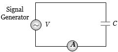
$A$ constant voltage at different frequencies is applied across a capacitance $C$ as shown in the figure. Which of the following graphs correctly depicts the variation of current with frequency?
A
B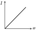
C
D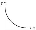
Solution
(B) For a capacitive circuit,the capacitive reactance is given by $X_C = \frac{1}{\omega C}$.
The current $I$ in the circuit is given by $I = \frac{V}{X_C}$.
Substituting the expression for $X_C$,we get $I = \frac{V}{1/(\omega C)} = V \omega C$.
Since the voltage $V$ and capacitance $C$ are constant,the current $I$ is directly proportional to the angular frequency $\omega$ $(I \propto \omega)$.
This represents a straight line passing through the origin. Therefore,the graph in option $B$ correctly depicts the variation of current with frequency.
0 likes
View Solution27
MediumMCQ
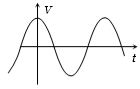
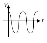
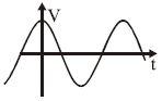
The voltage across a pure inductor is represented by the following diagram. Which one of the following diagrams will represent the current?
A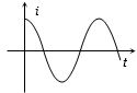
B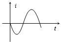
C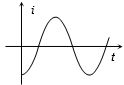
D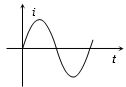
Solution
(C) In a purely inductive circuit,the voltage $V$ leads the current $i$ by a phase angle of $90^o$ (or $\pi/2$ radians).
If the voltage is represented as $V = V_m \sin(\omega t + \phi)$,then the current is represented as $i = I_m \sin(\omega t + \phi - 90^o) = -I_m \cos(\omega t + \phi)$.
Looking at the provided voltage graph,the voltage is at its maximum at $t = 0$. This corresponds to a cosine function $V = V_m \cos(\omega t)$.
Therefore,the current must be $i = I_m \sin(\omega t - 90^o) = -I_m \cos(\omega t)$.
At $t = 0$,$i = -I_m$,which means the current graph should start from the negative peak. Among the given options,the graph that represents a negative cosine wave is option $C$.
0 likes
View Solution28
MediumMCQ
In a pure inductive circuit, the curve between frequency $f$ and the reciprocal of inductive reactance $1/X_L$ is:
A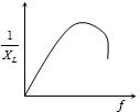
B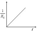
C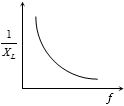
D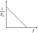
Solution
(C) The inductive reactance $X_L$ of an inductor is given by the formula: $X_L = 2\pi fL$, where $f$ is the frequency and $L$ is the inductance.
Taking the reciprocal of both sides, we get: $\frac{1}{X_L} = \frac{1}{2\pi fL}$.
This can be rewritten as: $\frac{1}{X_L} = \left( \frac{1}{2\pi L} \right) \cdot \frac{1}{f}$.
Let $y = \frac{1}{X_L}$ and $x = f$. Then the equation becomes $y = \frac{k}{x}$, where $k = \frac{1}{2\pi L}$ is a constant.
This is the equation of a rectangular hyperbola. Therefore, the graph between $\frac{1}{X_L}$ and $f$ is a rectangular hyperbola.
0 likes
View Solution29
MediumMCQ
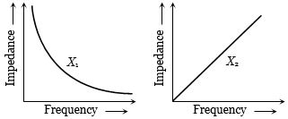
The graphs given below depict the dependence of two reactive impedances $X_1$ and $X_2$ on the frequency of the alternating e.m.f. applied individually to them. We can then say that
A
$X_1$ is an inductor and $X_2$ is a capacitor
B
$X_1$ is a resistor and $X_2$ is a capacitor
C
$X_1$ is a capacitor and $X_2$ is an inductor
D
$X_1$ is an inductor and $X_2$ is a resistor
Solution
(C) The capacitive reactance is given by $X_C = \frac{1}{2\pi f C}$,which implies that $X_C \propto \frac{1}{f}$. This represents a rectangular hyperbola,which matches the graph of $X_1$.
The inductive reactance is given by $X_L = 2\pi f L$,which implies that $X_L \propto f$. This represents a straight line passing through the origin,which matches the graph of $X_2$.
Therefore,$X_1$ is a capacitor and $X_2$ is an inductor.
The inductive reactance is given by $X_L = 2\pi f L$,which implies that $X_L \propto f$. This represents a straight line passing through the origin,which matches the graph of $X_2$.
Therefore,$X_1$ is a capacitor and $X_2$ is an inductor.
0 likes
View Solution30
MediumMCQ
Which of the following curves correctly represents the variation of capacitive reactance $X_C$ with frequency $f$?
A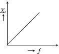
B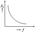
C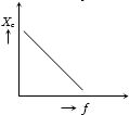
D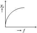
Solution
(B) The capacitive reactance $X_C$ is given by the formula:
$X_C = \frac{1}{\omega C} = \frac{1}{2\pi fC}$
This shows that $X_C$ is inversely proportional to the frequency $f$,i.e.,$X_C \propto \frac{1}{f}$.
As the frequency $f$ increases,the capacitive reactance $X_C$ decreases hyperbolically.
Therefore,the curve representing this relationship is a rectangular hyperbola,which corresponds to Graph $B$.
0 likes
View Solution31
DifficultMCQ
When an inductor is connected to an $AC$ source of frequency $\omega$,what is the frequency of the instantaneous power?
A
$\frac{\omega}{4}$
B
$\frac{\omega}{2}$
C
$\omega$
D
$2\omega$
Solution
(D) The voltage across the inductor is $E = E_0 \sin(\omega t)$.
In a pure inductor,the current lags the voltage by $\pi/2$,so $i = i_0 \sin(\omega t - \pi/2) = -i_0 \cos(\omega t)$.
The instantaneous power $P$ is given by $P = E \cdot i$.
$P = (E_0 \sin(\omega t)) \cdot (-i_0 \cos(\omega t))$.
$P = -E_0 i_0 \sin(\omega t) \cos(\omega t)$.
Using the trigonometric identity $\sin(2\theta) = 2 \sin(\theta) \cos(\theta)$,we get:
$P = -\frac{E_0 i_0}{2} \sin(2\omega t)$.
The frequency of the instantaneous power is the coefficient of $t$ divided by $2\pi$. Since the angular frequency of the power is $2\omega$,the frequency is $2\omega$.
0 likes
View Solution32
MediumMCQ
In an $ac$ circuit,an alternating voltage $e=200 \sqrt{2} \sin 100 t$ volts is connected to a capacitor of capacitance $1 \; \mu F$. The rms value of the current in the circuit is ..... $mA$.
A
$10$
B
$20$
C
$100$
D
$200$
Solution
(B) Given,the alternating voltage is $e = 200 \sqrt{2} \sin(100 t) \; V$.
Comparing this with the standard equation $e = E_0 \sin(\omega t)$,we get peak voltage $E_0 = 200 \sqrt{2} \; V$ and angular frequency $\omega = 100 \; rad/s$.
The rms voltage is $E_{\text{rms}} = \frac{E_0}{\sqrt{2}} = \frac{200 \sqrt{2}}{\sqrt{2}} = 200 \; V$.
The capacitance is $C = 1 \; \mu F = 1 \times 10^{-6} \; F$.
The capacitive reactance $X_C$ is given by $X_C = \frac{1}{\omega C} = \frac{1}{100 \times 10^{-6}} = \frac{1}{10^{-4}} = 10^4 \; \Omega$.
The rms current $I_{\text{rms}}$ is given by $I_{\text{rms}} = \frac{E_{\text{rms}}}{X_C} = \frac{200}{10^4} = 2 \times 10^{-2} \; A$.
Converting to milliamperes $(mA)$,$I_{\text{rms}} = 2 \times 10^{-2} \times 10^3 \; mA = 20 \; mA$.
0 likes
View Solution33
EasyMCQ
$A$ small signal voltage $V(t) = V_0 \sin(\omega t)$ is applied across an ideal capacitor $C$. Which of the following statements is correct?
A
Over a full cycle,the capacitor $C$ does not consume any energy from the voltage source.
B
Current $I(t)$ is in phase with voltage $V(t)$.
C
Current $I(t)$ leads voltage $V(t)$ by $180^\circ$.
D
Current $I(t)$ lags voltage $V(t)$ by $90^\circ$.
Solution
(A) When an ideal capacitor is connected to an $AC$ voltage source,the current $I(t)$ leads the voltage $V(t)$ by a phase angle of $90^\circ$.
Since the energy stored in the capacitor during the charging phase is returned to the circuit during the discharging phase,the net energy consumed by an ideal capacitor over a complete cycle is zero.
Therefore,statement $A$ is the correct statement.
Since the energy stored in the capacitor during the charging phase is returned to the circuit during the discharging phase,the net energy consumed by an ideal capacitor over a complete cycle is zero.
Therefore,statement $A$ is the correct statement.
0 likes
View Solution34
DifficultMCQ
Let $f = 50\, Hz$ and $C = 100\, \mu F$ in an $AC$ circuit containing a capacitor only. If the peak value of the current in the circuit is $1.57\, A$,the expression for the instantaneous voltage across the capacitor will be (assuming current is $I = I_m \sin(\omega t)$):
A
$E = 50\, \sin(100\, \pi t - \pi / 2)$
B
$E = 100\, \sin(50\, \pi t)$
C
$E = 50\, \sin(100\, \pi t)$
D
$E = 50\, \sin(100\, \pi t + \pi / 2)$
Solution
(A) Given: $f = 50\, Hz$,$C = 100\, \mu F = 10^{-4}\, F$,$I_m = 1.57\, A$.
Angular frequency $\omega = 2\pi f = 2 \times \pi \times 50 = 100\pi\, rad/s$.
Capacitive reactance $X_C = \frac{1}{\omega C} = \frac{1}{100\pi \times 10^{-4}} = \frac{100}{\pi} \approx \frac{100}{3.14} \approx 31.85\, \Omega$.
Peak voltage $E_m = I_m \times X_C = 1.57 \times 31.85 \approx 50\, V$.
In a purely capacitive circuit,the voltage lags behind the current by $\pi / 2$ radians. If current $I = I_m \sin(\omega t)$,then voltage $E = E_m \sin(\omega t - \pi / 2)$.
Substituting the values: $E = 50\, \sin(100\pi t - \pi / 2)$.
0 likes
View Solution35
EasyMCQ
$A$ capacitor of capacity $C$ has reactance $X$. If capacitance and frequency become double then reactance will be
A
$2X$
B
$4X$
C
$X/2$
D
$X/4$
Solution
(D) The capacitive reactance $X$ is given by the formula $X = \frac{1}{2 \pi f C}$,where $f$ is the frequency and $C$ is the capacitance.
Given that the new capacitance $C^{\prime} = 2C$ and the new frequency $f^{\prime} = 2f$.
The new reactance $X^{\prime}$ is calculated as:
$X^{\prime} = \frac{1}{2 \pi f^{\prime} C^{\prime}} = \frac{1}{2 \pi (2f) (2C)} = \frac{1}{4 (2 \pi f C)}$.
Since $X = \frac{1}{2 \pi f C}$,we substitute this into the equation:
$X^{\prime} = \frac{X}{4}$.
0 likes
View Solution36
DifficultMCQ
An $a.c.$ source of voltage $V$ and frequency $50\,Hz$ is connected to an inductor of $2\,H$ and negligible resistance. $A$ current of $r.m.s.$ value $I$ flows in the coil. When the frequency of the voltage is changed to $400\,Hz$ keeping the magnitude of $V$ the same,the current is now
A
$8I$ in phase with $V$
B
$4I$ and leading by $90^o$ from $V$
C
$I/4$ and lagging by $90^o$ from $V$
D
$I/8$ and lagging by $90^o$ from $V$
Solution
(D) The inductive reactance is given by $X_L = \omega L = 2\pi f L$.
For $f_1 = 50\,Hz$ and $L = 2\,H$,the reactance is $X_{L1} = 2\pi \times 50 \times 2 = 200\pi\,\Omega$.
The initial current is $I = V / X_{L1} = V / (200\pi)$.
When the frequency is changed to $f_2 = 400\,Hz$,the new inductive reactance is $X_{L2} = 2\pi \times 400 \times 2 = 1600\pi\,\Omega$.
The new current $I'$ is $I' = V / X_{L2} = V / (1600\pi)$.
Comparing the two currents: $I' = (V / 200\pi) / 8 = I / 8$.
In a purely inductive circuit,the current lags the voltage by $90^o$.
0 likes
View Solution37
MediumMCQ
An alternating voltage $V = 300\sqrt{2} \sin(100t)$ is connected to a $1 \ \mu F$ capacitor through an $AC$ ammeter. The reading of the ammeter will be.....$mA$.
A
$10$
B
$30$
C
$30\sqrt{2}$
D
$20\sqrt{2}$
Solution
(B) The given voltage is $V = V_{0} \sin(\omega t)$,where $V_{0} = 300\sqrt{2} \text{ V}$ and $\omega = 100 \text{ rad/s}$.
The capacitive reactance is $X_{C} = \frac{1}{\omega C} = \frac{1}{100 \times 1 \times 10^{-6}} = \frac{1}{10^{-4}} = 10^{4} \ \Omega$.
The peak current is $i_{0} = \frac{V_{0}}{X_{C}} = \frac{300\sqrt{2}}{10^{4}} = 300\sqrt{2} \times 10^{-4} \text{ A} = 30\sqrt{2} \times 10^{-3} \text{ A} = 30\sqrt{2} \text{ mA}$.
The $AC$ ammeter measures the $rms$ value of the current.
$i_{rms} = \frac{i_{0}}{\sqrt{2}} = \frac{30\sqrt{2}}{\sqrt{2}} = 30 \text{ mA}$.
0 likes
View Solution38
MediumMCQ
The voltage across a pure inductor is represented by the following diagram. Which of the following diagrams will represent the current?
A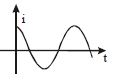
B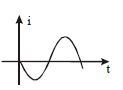
C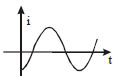
D
Solution
(D) In a pure inductor,the current lags behind the voltage by a phase angle of $\pi/2$ or $90^\circ$.
If the voltage is represented as $V = V_m \cos(\omega t)$,then the current is given by $i = I_m \cos(\omega t - \pi/2) = I_m \sin(\omega t)$.
The given voltage graph is a cosine wave starting at its maximum value at $t = 0$.
Since the current lags the voltage by $90^\circ$,the current graph should be a sine wave starting from zero at $t = 0$ and increasing in the positive direction.
Comparing this with the given options,the graph that represents a sine wave starting from zero at $t = 0$ is Option $D$.
0 likes
View Solution39
MediumMCQ
In the case of an inductor,
A
voltage lags the current by $\frac{\pi}{2}$
B
voltage leads the current by $\frac{\pi}{2}$
C
voltage leads the current by $\frac{\pi}{3}$
D
voltage leads the current by $\frac{\pi}{4}$
Solution
(B) In a pure inductive circuit,the voltage across the inductor leads the current flowing through it by a phase angle of $\frac{\pi}{2}$ radians (or $90^{\circ}$).
This occurs because the induced electromotive force $(EMF)$ in the inductor opposes the change in current,causing the voltage to reach its peak before the current.
This occurs because the induced electromotive force $(EMF)$ in the inductor opposes the change in current,causing the voltage to reach its peak before the current.
0 likes
View Solution40
MediumMCQ
The voltage across a pure inductor is represented by the following diagram. Which of the following diagrams will represent the current?
A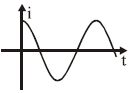
B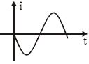
C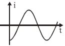
D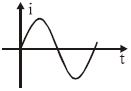
Solution
(C) For a pure inductor,the current $i$ lags behind the voltage $V$ by a phase angle of $\pi / 2$.
If the voltage is represented as $V = V_m \sin(\omega t)$,then the current is $i = I_m \sin(\omega t - \pi / 2) = -I_m \cos(\omega t)$.
In the given diagram,the voltage $V$ is shown as a sine wave starting from $0$ and increasing.
Therefore,the current $i$ must be a negative cosine wave,which starts at a negative maximum value at $t = 0$ and increases to $0$ at $t = \pi / (2\omega)$.
This corresponds to the graph shown in option $C$.
0 likes
View Solution41
MediumMCQ
$A$ sinusoidal voltage $V(t) = 100 \sin(500t)$ is applied across a pure inductance of $L = 0.02 \, H$. The current through the coil is:
A
$10 \cos(500t)$
B
$-10 \cos(500t)$
C
$10 \sin(500t)$
D
$-10 \sin(500t)$
Solution
(B) In a pure inductive circuit,the current always lags behind the electromotive force (emf) by a phase angle of $\frac{\pi}{2}$.
Given the voltage $V(t) = V_0 \sin(\omega t)$,the current is given by $I(t) = I_0 \sin(\omega t - \frac{\pi}{2})$.
Here,$V_0 = 100 \, V$ and $\omega = 500 \, rad/s$.
The peak current $I_0$ is calculated as $I_0 = \frac{V_0}{\omega L} = \frac{100}{500 \times 0.02} = \frac{100}{10} = 10 \, A$.
Substituting the values into the current equation:
$I(t) = 10 \sin(500t - \frac{\pi}{2})$.
Using the trigonometric identity $\sin(\theta - \frac{\pi}{2}) = -\cos(\theta)$,we get:
$I(t) = -10 \cos(500t)$.
0 likes
View Solution42
MediumMCQ
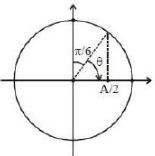
An alternating voltage $v(t) = 220 \sin(100 \pi t) \text{ V}$ is applied to a purely resistive load of $50 \, \Omega$. The time taken for the current to rise from zero to half of its peak value is ..... $ms$.
A
$2.2$
B
$3.3$
C
$5$
D
$7.2$
Solution
(B) The given alternating voltage is $v(t) = 220 \sin(100 \pi t)$.
Since the load is purely resistive,the current $i(t)$ is in phase with the voltage,given by $i(t) = I_0 \sin(100 \pi t)$,where $I_0$ is the peak current.
The current rises from zero to half of its peak value,so $i(t) = \frac{I_0}{2}$.
Substituting this into the equation: $\frac{I_0}{2} = I_0 \sin(100 \pi t) \implies \sin(100 \pi t) = \frac{1}{2}$.
This implies $100 \pi t = \frac{\pi}{6}$ (since $\sin(30^\circ) = 0.5$).
Solving for $t$: $t = \frac{\pi}{6 \times 100 \pi} = \frac{1}{600} \text{ s}$.
Converting to milliseconds: $t = \frac{1000}{600} \text{ ms} = 1.67 \text{ ms}$.
Wait,re-evaluating the question's intent based on the provided options and image: The image shows $\theta = \pi/6$ for $A/2$. If the question asks for the time to reach half the peak value,$t = 1.67 \text{ ms}$. If the question implies the time to reach the peak from half peak,it would be $t = \frac{\pi/2 - \pi/6}{100 \pi} = \frac{\pi/3}{100 \pi} = 3.33 \text{ ms}$. Given the options,$3.3 \text{ ms}$ is the intended answer.
0 likes
View Solution43
EasyMCQ
In a choke coil,the reactance $X_L$ and resistance $R$ are such that
A
$X_L = R$
B
$X_L >> R$
C
$X_L << R$
D
$X_L = \infty$
Solution
(B) choke coil is an inductor used to control the current in an $AC$ circuit without significant power loss. The power dissipated in an $AC$ circuit is given by $P = V_{rms} I_{rms} \cos \phi$,where $\cos \phi = \frac{R}{Z}$ is the power factor. For an ideal choke coil,the resistance $R$ should be as small as possible compared to the inductive reactance $X_L$. Therefore,for an efficient choke coil,$X_L >> R$.
0 likes
View Solution44
EasyMCQ
An $A.C.$ source is connected to a resistive circuit. Which of the following is true?
A
Current leads the voltage and both are in same phase
B
Current lags behind the voltage and both are in same phase
C
Current and voltage are in same phase
D
Any of the above may be true depending upon the value of resistance
Solution
(C) In a pure resistive $AC$ circuit, the voltage $V = V_m \sin(\omega t)$ and the current $I = I_m \sin(\omega t)$ are in the same phase.
This means the phase difference between the voltage and the current is zero.
Therefore, the current and voltage reach their maximum and minimum values at the same time.
This means the phase difference between the voltage and the current is zero.
Therefore, the current and voltage reach their maximum and minimum values at the same time.
0 likes
View Solution45
MediumMCQ
If the current through an inductor of inductance $L$ is given by $I = I_0 \sin(\omega t)$,then the voltage across the inductor will be
A
$I_0 \omega L \sin(\omega t - \pi/2)$
B
$I_0 \omega L \sin(\omega t + \pi/2)$
C
$I_0 \omega L \sin(\omega t - \pi)$
D
None of these
Solution
(B) The current through the inductor is given by $I = I_0 \sin(\omega t)$.
The voltage across an inductor is given by $V_L = L \frac{dI}{dt}$.
Substituting the expression for $I$:
$V_L = L \frac{d}{dt} (I_0 \sin(\omega t))$
$V_L = L I_0 \omega \cos(\omega t)$.
Using the trigonometric identity $\cos(\theta) = \sin(\theta + \pi/2)$:
$V_L = I_0 \omega L \sin(\omega t + \pi/2)$.
Thus,the voltage leads the current by a phase of $\pi/2$.
0 likes
View Solution46
EasyMCQ
If we decrease the frequency of the applied $A.C.$ with a purely capacitive load,do $(1)$ the amplitude of $V_c$ and $(2)$ amplitude of $I_c$ increase,decrease,or remain the same?
A
$(1)$ increase $(2)$ same
B
$(1)$ same $(2)$ increase
C
$(1)$ same $(2)$ decrease
D
$(1)$ decrease $(2)$ same
Solution
(C) The amplitude of the applied voltage $V_c$ is independent of the frequency of the $A.C.$ source,so it remains the same.
The capacitive reactance is given by $X_c = \frac{1}{2\pi f C}$.
As the frequency $f$ decreases,the capacitive reactance $X_c$ increases.
The amplitude of the current is given by $I_c = \frac{V_c}{X_c}$.
Since $V_c$ is constant and $X_c$ increases,the amplitude of the current $I_c$ decreases.
The capacitive reactance is given by $X_c = \frac{1}{2\pi f C}$.
As the frequency $f$ decreases,the capacitive reactance $X_c$ increases.
The amplitude of the current is given by $I_c = \frac{V_c}{X_c}$.
Since $V_c$ is constant and $X_c$ increases,the amplitude of the current $I_c$ decreases.
0 likes
View Solution47
MediumMCQ
An inductor,a resistor,and a capacitor are joined in series with an $AC$ source. As the frequency of the source is slightly increased from a very low value,the reactance of the
A
inductor increases
B
resistor increases
C
capacitor increases
D
circuit increases
Solution
(A) The reactance of an inductor is given by $X_L = \omega L = 2 \pi f L$. As the frequency $f$ increases,$X_L$ increases.
The reactance of a capacitor is given by $X_C = \frac{1}{\omega C} = \frac{1}{2 \pi f C}$. As the frequency $f$ increases,$X_C$ decreases.
The resistance of a resistor $R$ is independent of frequency.
Since the question asks what happens as the frequency is increased from a very low value,the inductive reactance $(X_L)$ increases directly with frequency.
0 likes
View Solution48
MediumMCQ
Assertion : No power loss is associated with a pure capacitor in an $AC$ circuit.
Reason : No current is flowing in this circuit.
Reason : No current is flowing in this circuit.
A
If both Assertion and Reason are correct and the Reason is a correct explanation of the Assertion.
B
If both Assertion and Reason are correct but Reason is not a correct explanation of the Assertion.
C
If the Assertion is correct but Reason is incorrect.
D
If both the Assertion and Reason are incorrect.
Solution
(C) In an $AC$ circuit with a pure capacitor,the phase difference between voltage and current is $\phi = -\pi/2$.
The average power consumed is given by $P_{av} = E_v I_v \cos(\phi)$.
Substituting the value of $\phi$,we get $P_{av} = E_v I_v \cos(-\pi/2) = E_v I_v (0) = 0$.
Thus,there is no power loss in a pure capacitor circuit.
However,the Reason states that no current is flowing in the circuit,which is incorrect because an alternating current $(AC)$ does flow through the capacitor due to its capacitive reactance $X_C = 1/(2\pi f C)$.
Therefore,the Assertion is correct,but the Reason is incorrect.
0 likes
View Solution49
Medium
$A$ pure inductor of $25.0 \; mH$ is connected to a source of $220 \; V$. Find the inductive reactance and rms current in the circuit if the frequency of the source is $50 \; Hz$.
Solution
(A) The inductive reactance $X_L$ is given by the formula $X_L = 2 \pi \nu L$.
Given: $L = 25.0 \; mH = 25 \times 10^{-3} \; H$,$\nu = 50 \; Hz$,and $V_{rms} = 220 \; V$.
Substituting the values: $X_L = 2 \times 3.14 \times 50 \times 25 \times 10^{-3} \; \Omega = 7.85 \; \Omega$.
The rms current $I_{rms}$ is given by $I_{rms} = \frac{V_{rms}}{X_L}$.
Substituting the values: $I_{rms} = \frac{220 \; V}{7.85 \; \Omega} \approx 28.03 \; A$.
0 likes
View Solution50
Medium
$A$ lamp is connected in series with a capacitor. Predict your observations for $dc$ and $ac$ connections. What happens in each case if the capacitance of the capacitor is reduced?
Solution
(N/A) When a $dc$ source is connected to a capacitor, the capacitor gets charged and after charging, no current flows in the circuit; therefore, the lamp will not glow. There will be no change even if $C$ is reduced.
With an $ac$ source, the capacitor offers capacitive reactance $X_C = 1 / (\omega C)$ and current flows in the circuit. Consequently, the lamp will shine.
If the capacitance $C$ is reduced, the capacitive reactance $X_C = 1 / (\omega C)$ increases. As a result, the current in the circuit decreases, and the lamp will shine less brightly than before.
0 likes
View SolutionAlternating Current — Only Inductor, Only Capacitor and Only Resistor Circuit · Frequently Asked Questions
1Are these Alternating Current questions useful for JEE and NEET?
Yes. All questions in this section are mapped to JEE Main and NEET exam patterns. Previous year questions from JEE Main, NEET, GUJCET and state-level exams are included with full solutions.
2Can I switch to Hindi or Gujarati for these questions?
Yes. Use the language tabs in the hero section or the sidebar to view the same questions and solutions in English, Hindi or Gujarati.
3How do I generate a question paper from this subtopic?
Use the Vedclass Exam Paper Generator — select the chapter and subtopic, set difficulty, and generate Sets A, B, C, D automatically. First 3 chapters of every subject are free.
Vedclass Products
For Students
Vedclass Test Series
Mock tests in real JEE/NEET style with performance analysis. 5-day free trial.
Start Free TrialFor Teachers
Exam Paper Generator
Generate Set A/B/C/D papers from this chapter in 2 minutes. 3 chapters free.
Try FreeFor Institutes
Online Exam Module
Live online exams with unlimited students, 360° analytics & white-label branding.
See DemoFor Teachers & Institutes
Generate a Alternating Current Exam Paper in 2 Minutes
Select subtopic & difficulty — Sets A, B, C, D auto-generated with No Repeat logic.
First 3 chapters of every subject are free — no payment required.