
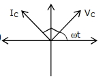
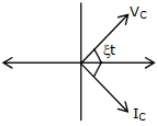
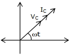
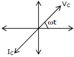
In a circuit consisting of a capacitance and a generator with alternating emf $E_{g}=E_{g0} \sin \omega t$,$V_{C}$ and $I_{C}$ are the voltage and current. The correct phasor diagram for such a circuit is:
- A
- B
- C
- D
Explore More
Similar Questions
Explain $AC$ voltage applied to a resistor and explain it with a necessary graph.
Medium
View SolutionIf we decrease the frequency of the applied $A.C.$ with a purely capacitive load,do $(1)$ the amplitude of $V_c$ and $(2)$ amplitude of $I_c$ increase,decrease,or remain the same?
$A$ small signal voltage $V(t) = V_0 \sin(\omega t)$ is applied across an ideal capacitor $C$. Which of the following statements is correct?
An alternating $emf$ $E = 440 \sin(100 \pi t)$ is applied to a circuit containing an inductance of $\frac{\sqrt{2}}{\pi} \text{ H}$. If an $AC$ ammeter is connected in the circuit,its reading will be $....... \text{ A}$.
DifficultJEE MAIN 2022
View SolutionThe value of the current through an inductance of $1 \, H$ and of negligible resistance,when connected to an $ac$ source of $200 \, V$ and $50 \, Hz$ is: (in $, A$)
Easy
View SolutionVedclass Products
For Students
Vedclass Test Series
Mock tests in real JEE/NEET style with performance analysis. 5-day free trial.
Start Free TrialFor Teachers
Exam Paper Generator
Generate Set A/B/C/D exam papers from 7.5L+ questions in 2 minutes. 3 chapters free.
Try FreeFor Institutes
Online Exam Module
Live online exams with unlimited students, 360° analytics & white-label branding.
See Demo