
A English
Inductance, Capacitance and Resistance in Series and Parallel Questions in English
Class 12 Physics · Alternating Current · Inductance, Capacitance and Resistance in Series and Parallel
138+
Questions
English
Language
100%
With Solutions
Showing 49 of 138 questions in English
51
DifficultMCQ
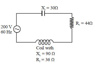
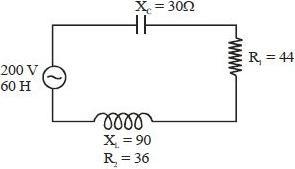
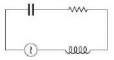
As shown in the figure,a series circuit connected across a $200\, V$,$60\, Hz$ line consists of a capacitor of capacitive reactance $30\,\Omega$,a non-inductive resistor of $44\,\Omega$,and a coil of inductive reactance $90\,\Omega$ and resistance $36\,\Omega$. The power dissipated in the coil is......$W$.
A
$320$
B
$176$
C
$144$
D
$0$
Solution
(C) The total resistance of the circuit is $R = R_1 + R_2 = 44\,\Omega + 36\,\Omega = 80\,\Omega$.
The net reactance of the circuit is $X = X_L - X_C = 90\,\Omega - 30\,\Omega = 60\,\Omega$.
The impedance of the circuit is $Z = \sqrt{R^2 + X^2} = \sqrt{80^2 + 60^2} = \sqrt{6400 + 3600} = \sqrt{10000} = 100\,\Omega$.
The current in the series circuit is $I = \frac{V}{Z} = \frac{200\, V}{100\,\Omega} = 2\, A$.
The power dissipated in the coil is due to its internal resistance $R_2 = 36\,\Omega$. Therefore,$P = I^2 R_2 = (2)^2 \times 36 = 4 \times 36 = 144\, W$.
0 likes
View Solution52
EasyMCQ
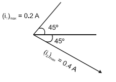
For the circuit shown in the figure,the current through the inductor is $0.9\,A$ while the current through the capacitor is $0.4\,A$. Then
A
current drawn from generator $I = 1.13\,A$
B
$\omega = 1/(1.5\,LC)$
C
$I = 0.5\,A$
D
$I = 0.6\,A$
Solution
(C) In an $AC$ circuit with an inductor and a capacitor connected in parallel,the current through the inductor $(I_L)$ lags the voltage by $90^{\circ}$,and the current through the capacitor $(I_C)$ leads the voltage by $90^{\circ}$.
Thus,the currents $I_L$ and $I_C$ are in opposite phases,i.e.,they have a phase difference of $180^{\circ}$.
The total current $I$ drawn from the generator is the vector sum of these currents:
$I = |I_L - I_C|$
Given $I_L = 0.9\,A$ and $I_C = 0.4\,A$.
Therefore,$I = |0.9 - 0.4| = 0.5\,A$.
Thus,the currents $I_L$ and $I_C$ are in opposite phases,i.e.,they have a phase difference of $180^{\circ}$.
The total current $I$ drawn from the generator is the vector sum of these currents:
$I = |I_L - I_C|$
Given $I_L = 0.9\,A$ and $I_C = 0.4\,A$.
Therefore,$I = |0.9 - 0.4| = 0.5\,A$.
0 likes
View Solution53
Medium
$A$ sinusoidal voltage of peak value $283 \;V$ and frequency $50 \;Hz$ is applied to a series $LCR$ circuit in which $R = 3 \;\Omega, L = 25.48 \;mH,$ and $C = 796 \;\mu F.$ Find
$(a)$ the impedance of the circuit;
$(b)$ the phase difference between the voltage across the source and the current;
$(c)$ the power dissipated in the circuit; and
$(d)$ the power factor.
$(a)$ the impedance of the circuit;
$(b)$ the phase difference between the voltage across the source and the current;
$(c)$ the power dissipated in the circuit; and
$(d)$ the power factor.
Solution
(A) To find the impedance of the circuit,we first calculate $X_{L}$ and $X_{C}$.
$X_{L} = 2 \pi \nu L = 2 \times 3.14 \times 50 \times 25.48 \times 10^{-3} \; \Omega = 8 \; \Omega$.
$X_{C} = \frac{1}{2 \pi \nu C} = \frac{1}{2 \times 3.14 \times 50 \times 796 \times 10^{-6}} = 4 \; \Omega$.
Therefore,$Z = \sqrt{R^{2} + (X_{L} - X_{C})^{2}} = \sqrt{3^{2} + (8 - 4)^{2}} = 5 \; \Omega$.
$(b)$ Phase difference,$\phi = \tan^{-1} \left( \frac{X_{L} - X_{C}}{R} \right) = \tan^{-1} \left( \frac{8 - 4}{3} \right) = \tan^{-1} \left( \frac{4}{3} \right) \approx 53.1^{\circ}$.
Since $\phi$ is positive,the current lags the voltage.
$(c)$ The power dissipated in the circuit is $P = I_{rms}^{2} R$.
$I_{rms} = \frac{V_{m}}{\sqrt{2} Z} = \frac{283}{\sqrt{2} \times 5} \approx 40 \; A$.
Therefore,$P = (40)^{2} \times 3 = 4800 \; W$.
$(d)$ Power factor = $\cos \phi = \frac{R}{Z} = \frac{3}{5} = 0.6$.
0 likes
View Solution54
Medium
$A$ circuit containing an $80 \; mH$ inductor,a resistance of $15 \; \Omega$,and a $60 \; \mu F$ capacitor in series is connected to a $230 \; V, 50 \; Hz$ supply. Obtain the average power transferred to each element of the circuit,and the total power absorbed.
Solution
(N/A) Given: Inductance $L = 80 \; mH = 80 \times 10^{-3} \; H$,Capacitance $C = 60 \; \mu F = 60 \times 10^{-6} \; F$,Resistance $R = 15 \; \Omega$,Voltage $V = 230 \; V$,Frequency $f = 50 \; Hz$.
Angular frequency $\omega = 2 \pi f = 2 \pi \times 50 = 100 \pi \; rad/s \approx 314.16 \; rad/s$.
Inductive reactance $X_L = \omega L = 100 \pi \times 80 \times 10^{-3} \approx 25.13 \; \Omega$.
Capacitive reactance $X_C = \frac{1}{\omega C} = \frac{1}{100 \pi \times 60 \times 10^{-6}} \approx 53.05 \; \Omega$.
Impedance $Z = \sqrt{R^2 + (X_L - X_C)^2} = \sqrt{15^2 + (25.13 - 53.05)^2} = \sqrt{225 + (-27.92)^2} = \sqrt{225 + 779.53} = \sqrt{1004.53} \approx 31.69 \; \Omega$.
Current $I = \frac{V}{Z} = \frac{230}{31.69} \approx 7.26 \; A$.
Average power transferred to the inductor $P_L = 0 \; W$ (since phase difference is $90^\circ$).
Average power transferred to the capacitor $P_C = 0 \; W$ (since phase difference is $90^\circ$).
Average power transferred to the resistor $P_R = I^2 R = (7.26)^2 \times 15 \approx 790.5 \; W$.
Total power absorbed by the circuit $P_{total} = P_R + P_L + P_C = 790.5 + 0 + 0 = 790.5 \; W$.
0 likes
View Solution55
Medium
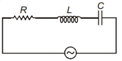
Obtain the relation for the voltage applied to a series $LCR$ circuit.
Solution
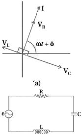
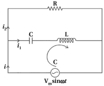
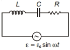
(N/A) Consider a series $LCR$ circuit connected to an $AC$ source with electromotive force $\varepsilon = V_m \sin \omega t$.
Let $q$ be the charge on the capacitor and $I$ be the current in the circuit at any time $t$. According to Kirchhoff's voltage law (loop rule),the sum of potential drops across the inductor $(V_L)$,resistor $(V_R)$,and capacitor $(V_C)$ must equal the applied source voltage $V$.
$V = V_L + V_R + V_C$
Substituting the expressions for potential differences:
$V = L \frac{dI}{dt} + IR + \frac{q}{C}$
Where:
$V_L = L \frac{dI}{dt}$ is the potential difference across the inductor.
$V_R = IR$ is the potential difference across the resistor.
$V_C = \frac{q}{C}$ is the potential difference across the capacitor.
0 likes
View Solution56
Medium
Obtain the relation of phase between instantaneous current and voltage with the help of a phasor diagram for a series $LCR$ circuit.
Solution
(N/A) In a series $LCR$ circuit,the current $I$ is the same through all components at any instant.
Let the current be $I = I_m \sin(\omega t)$.
The voltage across the resistor $V_R$ is in phase with the current $I$.
The voltage across the inductor $V_L$ leads the current $I$ by $\pi/2$.
The voltage across the capacitor $V_C$ lags behind the current $I$ by $\pi/2$.
The total voltage $V$ is the phasor sum of $V_R$,$V_L$,and $V_C$. Since $V_L$ and $V_C$ are in opposite directions,their resultant is $(V_L - V_C)$.
Using the phasor diagram,the resultant voltage $V$ is given by $V = \sqrt{V_R^2 + (V_L - V_C)^2}$.
The phase angle $\phi$ between the source voltage and current is given by $\tan \phi = \frac{V_L - V_C}{V_R} = \frac{I_m X_L - I_m X_C}{I_m R} = \frac{X_L - X_C}{R}$.
Thus,the phase relation is $\phi = \tan^{-1} \left( \frac{X_L - X_C}{R} \right)$.
0 likes
View Solution57
Medium
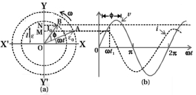
Draw phasor diagrams for $X_C > X_L$ and $X_C < X_L$,and state the disadvantages of the phasor method.
Solution
(N/A) If $X_C > X_L$,the phase angle $\phi$ is positive and the circuit becomes capacitive; consequently,the current in the circuit leads the source voltage.
If $X_C < X_L$,the phase angle $\phi$ is negative and the circuit becomes inductive; consequently,the source voltage in the circuit leads the current.
The phasor diagram and the variation of $V$ and $I$ with $\omega t$ for the case $X_C > X_L$ are shown in the figure.
Thus,we have obtained the amplitude and phase of the current for an $LCR$ series circuit using the technique of phasors,but this method has certain disadvantages:
$1$. The phasor diagram provides no information about the initial conditions.
$2$. One can choose any arbitrary value of $t$ and draw different phasors. The solution obtained is called the steady-state solution,which is not a general solution.
$3$. Furthermore,there exists a transient solution that persists even for $V = 0$.
The general solution is the sum of the transient solution and the steady-state solution. After a sufficiently long time,the effects of the transient solution die out,and the behavior of the circuit is described by the steady-state solution.
0 likes
View Solution58
Medium
Obtain an analytical solution for the relation of phase between instantaneous current and voltage for an $LCR$ series $AC$ circuit.
Solution
(N/A) The voltage equation for an $L-C-R$ series circuit is given by Kirchhoff's voltage law:
$L \frac{dI}{dt} + RI + \frac{q}{C} = V$
Substituting $V = V_m \sin \omega t$,we get:
$L \frac{dI}{dt} + RI + \frac{q}{C} = V_m \sin \omega t$ ... $(1)$
Since $I = \frac{dq}{dt}$,we have $\frac{dI}{dt} = \frac{d^2q}{dt^2}$. Substituting this into $(1)$:
$L \frac{d^2q}{dt^2} + R \frac{dq}{dt} + \frac{q}{C} = V_m \sin \omega t$
Dividing by $L$:
$\frac{d^2q}{dt^2} + \frac{R}{L} \frac{dq}{dt} + \frac{q}{LC} = \frac{V_m}{L} \sin \omega t$ ... $(2)$
This is the equation for a forced,damped oscillator. Let the solution be $q = q_m \sin(\omega t + \theta)$ ... $(3)$
Then $\frac{dq}{dt} = q_m \omega \cos(\omega t + \theta)$ ... $(4)$ and $\frac{d^2q}{dt^2} = -q_m \omega^2 \sin(\omega t + \theta)$ ... $(5)$
Substituting $(3), (4),$ and $(5)$ into $(2)$:
$-q_m \omega^2 L \sin(\omega t + \theta) + R q_m \omega \cos(\omega t + \theta) + \frac{q_m}{C} \sin(\omega t + \theta) = V_m \sin \omega t$
$q_m \omega [R \cos(\omega t + \theta) + (\frac{1}{\omega C} - \omega L) \sin(\omega t + \theta)] = V_m \sin \omega t$
Using $X_C = \frac{1}{\omega C}$ and $X_L = \omega L$,and impedance $Z = \sqrt{R^2 + (X_L - X_C)^2}$,we define $\cos \phi = \frac{R}{Z}$ and $\sin \phi = \frac{X_L - X_C}{Z}$.
This leads to the phase relation where the current $I = I_m \sin(\omega t + \phi)$ lags or leads the voltage by phase angle $\phi = \tan^{-1}(\frac{X_L - X_C}{R})$.
0 likes
View Solution59
MediumMCQ
What is the impedance of an $L-C-R$ series $AC$ circuit?
A
$Z = \sqrt{R^2 + (X_L - X_C)^2}$
B
$Z = R + X_L + X_C$
C
$Z = \sqrt{R^2 + (X_L + X_C)^2}$
D
$Z = \sqrt{R^2 - (X_L - X_C)^2}$
Solution
(A) In an $L-C-R$ series $AC$ circuit,the voltage across the resistor $(V_R)$ is in phase with the current $(I)$.
The voltage across the inductor $(V_L)$ leads the current by $90^\circ$,and the voltage across the capacitor $(V_C)$ lags behind the current by $90^\circ$.
The net reactance of the circuit is $(X_L - X_C)$.
Using the phasor diagram,the total voltage $V$ is given by $V = \sqrt{V_R^2 + (V_L - V_C)^2}$.
Since $V = IZ$,$V_R = IR$,$V_L = IX_L$,and $V_C = IX_C$,we substitute these into the equation:
$IZ = \sqrt{(IR)^2 + (IX_L - IX_C)^2}$
$IZ = I \sqrt{R^2 + (X_L - X_C)^2}$
Therefore,the impedance $Z$ is $Z = \sqrt{R^2 + (X_L - X_C)^2}$.
0 likes
View Solution60
Easy
Write the differential equation of charge for $L-C-R$ series $AC$ circuit.
Solution
(N/A) In an $L-C-R$ series circuit,the sum of potential drops across the inductor $(L)$,resistor $(R)$,and capacitor $(C)$ is equal to the applied electromotive force $(E(t))$.
According to Kirchhoff's voltage law:
$L \frac{dI}{dt} + IR + \frac{q}{C} = E(t)$
Since the current $I = \frac{dq}{dt}$,the rate of change of current is $\frac{dI}{dt} = \frac{d^2q}{dt^2}$.
Substituting these into the equation,we get:
$L \frac{d^2q}{dt^2} + R \frac{dq}{dt} + \frac{q}{C} = E(t)$
This is the second-order linear differential equation for the charge $q$ in an $L-C-R$ series circuit.
0 likes
View Solution61
Medium
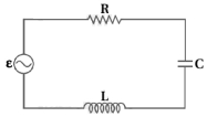
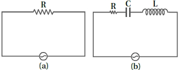
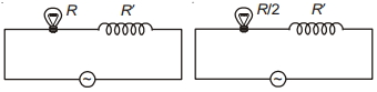
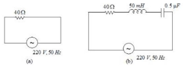
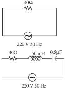
Study the circuits $(a)$ and $(b)$ shown in the figure and answer the following questions.
$(a)$ Under which conditions would the $rms$ currents in the two circuits be the same?
$(b)$ Can the $rms$ current in circuit $(b)$ be larger than that in $(a)$?
$(a)$ Under which conditions would the $rms$ currents in the two circuits be the same?
$(b)$ Can the $rms$ current in circuit $(b)$ be larger than that in $(a)$?
Solution
(N/A) Let the $rms$ current in circuit $(a)$ be $I_{a}$ and in circuit $(b)$ be $I_{b}$.
For circuit $(a)$,the impedance is $Z_{a} = R$. Thus,$I_{a} = \frac{V_{rms}}{R}$.
For circuit $(b)$,the impedance is $Z_{b} = \sqrt{R^{2} + (X_{L} - X_{C})^{2}}$. Thus,$I_{b} = \frac{V_{rms}}{\sqrt{R^{2} + (X_{L} - X_{C})^{2}}}$.
$(a)$ For $I_{a} = I_{b}$,we must have $Z_{a} = Z_{b}$.
$\therefore R = \sqrt{R^{2} + (X_{L} - X_{C})^{2}}$.
Squaring both sides,$R^{2} = R^{2} + (X_{L} - X_{C})^{2}$,which implies $(X_{L} - X_{C})^{2} = 0$,or $X_{L} = X_{C}$.
This is the condition of electrical resonance.
$(b)$ Since $Z_{b} = \sqrt{R^{2} + (X_{L} - X_{C})^{2}}$,it is clear that $Z_{b} \geq R$ for all values of $X_{L}$ and $X_{C}$.
Since $I_{b} = \frac{V_{rms}}{Z_{b}}$ and $I_{a} = \frac{V_{rms}}{R}$,and $Z_{b} \geq R$,it follows that $I_{b} \leq I_{a}$.
Therefore,the $rms$ current in circuit $(b)$ can never be larger than that in circuit $(a)$.
0 likes
View Solution62
EasyMCQ
How does the sign of the phase angle $\phi$,by which the supply voltage leads the current in an $LCR$ series circuit,change as the supply frequency is gradually increased from very low to very high values?
A
It remains positive throughout.
B
It remains negative throughout.
C
It changes from positive to negative.
D
It changes from negative to positive.
Solution
(D) The phase angle $\phi$ by which the supply voltage leads the current in an $LCR$ series circuit is given by the relation: $\tan \phi = \frac{X_L - X_C}{R} = \frac{2 \pi \nu L - \frac{1}{2 \pi \nu C}}{R}$.
At very low frequencies $(\nu \to 0)$,the capacitive reactance $X_C = \frac{1}{2 \pi \nu C}$ is very large,making $X_L - X_C$ negative. Thus,$\tan \phi$ is negative,meaning the voltage lags behind the current (or the phase angle is negative).
As the frequency $\nu$ increases and reaches the resonant frequency $\nu_r = \frac{1}{2 \pi \sqrt{LC}}$,the inductive reactance $X_L$ equals the capacitive reactance $X_C$,so $X_L - X_C = 0$ and $\phi = 0$.
At very high frequencies $(\nu \to \infty)$,the inductive reactance $X_L = 2 \pi \nu L$ becomes very large,making $X_L - X_C$ positive. Thus,$\tan \phi$ is positive,meaning the voltage leads the current (or the phase angle is positive).
Therefore,as the frequency increases from very low to very high values,the sign of the phase angle $\phi$ changes from negative to positive.
0 likes
View Solution63
Medium
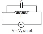
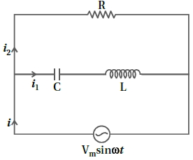
Consider the parallel $LCR$ circuit shown in the figure. Find the net current $i$ and the phase of $i$. Show that $i = \frac{V}{Z}$. Find the impedance $Z$ for this circuit.
Solution
(N/A) The circuit consists of a resistor $R$ in parallel with a series combination of a capacitor $C$ and an inductor $L$. The voltage across both branches is $V = V_m \sin \omega t$.
$1$. Current through the resistor branch $(i_R)$:
$i_R = \frac{V}{R} = \frac{V_m}{R} \sin \omega t$.
$2$. Current through the $LC$ branch $(i_{LC})$:
The impedance of the $LC$ series branch is $Z_{LC} = j(\omega L - \frac{1}{\omega C})$.
The current is $i_{LC} = \frac{V}{Z_{LC}} = \frac{V_m \sin \omega t}{j(\omega L - \frac{1}{\omega C})} = \frac{V_m \sin(\omega t - \pi/2)}{\omega L - 1/(\omega C)}$ (if $\omega L > 1/\omega C$).
$3$. Total current $i$:
$i = i_R + i_{LC} = \frac{V_m}{R} \sin \omega t + \frac{V_m}{\omega L - 1/(\omega C)} \sin(\omega t - \pi/2)$.
Using phasor addition,the total current is $i = I_m \sin(\omega t + \phi)$,where $I_m = V_m \sqrt{(\frac{1}{R})^2 + (\frac{1}{\omega L - 1/(\omega C)})^2}$.
$4$. Impedance $Z$:
Since $i = V/Z$,the total impedance $Z$ is given by $\frac{1}{Z} = \sqrt{(\frac{1}{R})^2 + (\frac{1}{\omega L - 1/(\omega C)})^2}$.
Therefore,$Z = \frac{R |\omega L - 1/(\omega C)|}{\sqrt{R^2 + (\omega L - 1/(\omega C))^2}}$.
0 likes
View Solution64
DifficultMCQ
$A$ $750\, Hz$,$20\, V$ (rms) source is connected to a resistance of $100\, \Omega$,an inductance of $0.1803\, H$,and a capacitance of $10\, \mu F$,all in series. The time in which the resistance (heat capacity $2\, J/^{\circ}C$) will get heated by $10^{\circ}C$ (assume no loss of heat to the surroundings) is close to $.....s$.
A
$418$
B
$245$
C
$348$
D
$365$
Solution
(C) Given: $f = 750\, Hz$,$V_{rms} = 20\, V$,$R = 100\, \Omega$,$L = 0.1803\, H$,$C = 10\, \mu F = 10 \times 10^{-6}\, F$,$S = 2\, J/^{\circ}C$,$\Delta T = 10^{\circ}C$.
First,calculate the inductive reactance $X_L$ and capacitive reactance $X_C$:
$X_L = 2\pi fL = 2 \times 3.14159 \times 750 \times 0.1803 \approx 849.6\, \Omega$.
$X_C = \frac{1}{2\pi fC} = \frac{1}{2 \times 3.14159 \times 750 \times 10 \times 10^{-6}} \approx 21.2\, \Omega$.
Calculate the impedance $Z$:
$Z = \sqrt{R^2 + (X_L - X_C)^2} = \sqrt{100^2 + (849.6 - 21.2)^2} = \sqrt{10000 + (828.4)^2} \approx \sqrt{10000 + 686246} \approx \sqrt{696246} \approx 834.4\, \Omega$.
The power dissipated in the resistor is $P = I_{rms}^2 R = \left(\frac{V_{rms}}{Z}\right)^2 R = \left(\frac{20}{834.4}\right)^2 \times 100 \approx (0.02397)^2 \times 100 \approx 0.05746\, W$ (or $J/s$).
The heat required is $Q = S \cdot \Delta T = 2\, J/^{\circ}C \times 10^{\circ}C = 20\, J$.
The time $t$ required is $t = \frac{Q}{P} = \frac{20}{0.05746} \approx 348.07\, s$.
Thus,the time is close to $348\, s$.
0 likes
View Solution65
MediumMCQ
In a series $LR$ circuit,power of $400 \ W$ is dissipated from a source of $250 \ V, 50 \ Hz$. The power factor of the circuit is $0.8$. In order to bring the power factor to unity,a capacitor of value $C$ is added in series to the $L$ and $R$. Taking the value of $C$ as $(\frac{n}{3 \pi}) \mu F$,then the value of $n$ is $......$
A
$200$
B
$250$
C
$350$
D
$400$
Solution
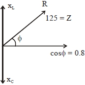
(D) Given: $P = 400 \ W$,$V_{rms} = 250 \ V$,$f = 50 \ Hz$,$\cos \phi = 0.8$.
$1$. Calculate impedance $Z$:
$P = V_{rms} I_{rms} \cos \phi = \frac{V_{rms}^2}{Z} \cos \phi$
$400 = \frac{250^2}{Z} \times 0.8$
$Z = \frac{62500 \times 0.8}{400} = \frac{50000}{400} = 125 \ \Omega$.
$2$. Calculate resistance $R$ and inductive reactance $X_L$:
$R = Z \cos \phi = 125 \times 0.8 = 100 \ \Omega$.
$X_L = Z \sin \phi = 125 \times \sqrt{1 - 0.8^2} = 125 \times 0.6 = 75 \ \Omega$.
$3$. For unity power factor,the circuit must be in resonance,so $X_C = X_L = 75 \ \Omega$.
$X_C = \frac{1}{2 \pi f C} = 75$
$C = \frac{1}{2 \pi \times 50 \times 75} = \frac{1}{7500 \pi} \ F = \frac{10^6}{7500 \pi} \ \mu F = \frac{10000}{75 \pi} \ \mu F = \frac{400}{3 \pi} \ \mu F$.
Comparing with $C = (\frac{n}{3 \pi}) \ \mu F$,we get $n = 400$.
0 likes
View Solution66
DifficultMCQ
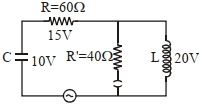
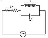
The angular frequency of alternating current in an $L-C-R$ circuit is $100 \, rad/s$. The components connected are shown in the figure. Find the value of the inductance of the coil and the capacity of the condenser.
A
$0.8 \, H$ and $150 \, \mu F$
B
$0.8 \, H$ and $250 \, \mu F$
C
$1.33 \, H$ and $250 \, \mu F$
D
$1.33 \, H$ and $150 \, \mu F$
Solution
(B) Given angular frequency $\omega = 100 \, rad/s$.
$1$. For the capacitor branch:
The current through the $60 \, \Omega$ resistor is $I_C = \frac{V_R}{R} = \frac{15 \, V}{60 \, \Omega} = 0.25 \, A = \frac{1}{4} \, A$.
Since the capacitor is in series with this resistor,the same current flows through the capacitor.
Using $V_C = I_C X_C = I_C \cdot \frac{1}{\omega C}$:
$10 = \frac{1}{4} \cdot \frac{1}{100 \cdot C}$
$10 = \frac{1}{400 C} \Rightarrow C = \frac{1}{4000} \, F = 0.25 \times 10^{-3} \, F = 250 \, \mu F$.
$2$. For the inductor branch:
The current through the $40 \, \Omega$ resistor is $I_{R'} = \frac{V_{R'}}{R'} = \frac{20 \, V}{40 \, \Omega} = 0.5 \, A = \frac{1}{2} \, A$.
Since the inductor is in parallel with this resistor branch,the total current in this parallel section is the sum of currents. However,looking at the circuit,the inductor is in parallel with the $R'$ branch. The voltage across the inductor is $20 \, V$.
$V_L = I_L X_L = I_L \cdot \omega L$
$20 = I_L \cdot 100 \cdot L$.
Assuming the current through the inductor is $I_L = 0.25 \, A$ (as derived from the node analysis where the total current splits):
$20 = 0.25 \cdot 100 \cdot L$
$20 = 25 \cdot L \Rightarrow L = \frac{20}{25} = 0.8 \, H$.
0 likes
View Solution67
DifficultMCQ
An $LCR$ circuit contains resistance of $110 \, \Omega$ and a supply of $220 \, V$ at $300 \, rad/s$ angular frequency. If only capacitance is removed from the circuit,current lags behind the voltage by $45^{\circ}$. If on the other hand,only inductor is removed,the current leads by $45^{\circ}$ with the applied voltage. The rms current flowing in the circuit will be ...... $A$.
A
$1$
B
$2.5$
C
$1.5$
D
$2$
Solution
(D) Given: $R = 110 \, \Omega$,$V = 220 \, V$,$\omega = 300 \, rad/s$.
When capacitance is removed,the circuit is an $LR$ circuit. The phase angle is given by $\tan \phi = \frac{X_L}{R}$. Since current lags by $45^{\circ}$,$\tan 45^{\circ} = \frac{X_L}{R} = 1$,so $X_L = R$.
When the inductor is removed,the circuit is an $RC$ circuit. The phase angle is given by $\tan \phi = \frac{X_C}{R}$. Since current leads by $45^{\circ}$,$\tan 45^{\circ} = \frac{X_C}{R} = 1$,so $X_C = R$.
Since $X_L = R$ and $X_C = R$,it implies $X_L = X_C$.
In an $LCR$ circuit,when $X_L = X_C$,the circuit is in resonance.
At resonance,the impedance $Z = R$.
The rms current $I = \frac{V}{Z} = \frac{V}{R} = \frac{220}{110} = 2 \, A$.
0 likes
View Solution68
EasyMCQ
In an $AC$ circuit,an inductor,a capacitor,and a resistor are connected in series with $X_{L} = R = X_{C}$. The impedance of this circuit is:
A
$2 R^{2}$
B
Zero
C
$R$
D
$R \sqrt{2}$
Solution
(C) The impedance $Z$ of an $LCR$ series circuit is given by the formula: $Z = \sqrt{(X_{L} - X_{C})^{2} + R^{2}}$.
Given that $X_{L} = R$ and $X_{C} = R$,we have $X_{L} = X_{C}$.
Substituting these values into the impedance formula:
$Z = \sqrt{(R - R)^{2} + R^{2}}$
$Z = \sqrt{0^{2} + R^{2}}$
$Z = \sqrt{R^{2}}$
$Z = R$.
Therefore,the impedance of the circuit is $R$.
Given that $X_{L} = R$ and $X_{C} = R$,we have $X_{L} = X_{C}$.
Substituting these values into the impedance formula:
$Z = \sqrt{(R - R)^{2} + R^{2}}$
$Z = \sqrt{0^{2} + R^{2}}$
$Z = \sqrt{R^{2}}$
$Z = R$.
Therefore,the impedance of the circuit is $R$.
0 likes
View Solution69
DifficultMCQ
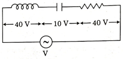
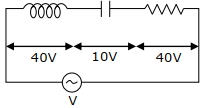
An inductor of inductance $L$,a capacitor of capacitance $C$,and a resistor of resistance $R$ are connected in series to an $AC$ source of potential difference $V$ volts as shown in the figure. The potential difference across $L$,$C$,and $R$ is $40 \, V$,$10 \, V$,and $40 \, V$,respectively. The amplitude of the current flowing through the $LCR$ series circuit is $10 \sqrt{2} \, A$. The impedance of the circuit is .......... $\Omega$.
A
$4 \sqrt{2}$
B
$5 / \sqrt{2}$
C
$4$
D
$5$
Solution
(D) Given:
Amplitude of current,$I_{0} = 10 \sqrt{2} \, A$.
Potential difference across inductor,$V_{L} = 40 \, V$.
Potential difference across capacitor,$V_{C} = 10 \, V$.
Potential difference across resistor,$V_{R} = 40 \, V$.
Step $1$: Calculate the $RMS$ current $(I_{RMS})$.
$I_{RMS} = \frac{I_{0}}{\sqrt{2}} = \frac{10 \sqrt{2}}{\sqrt{2}} = 10 \, A$.
Step $2$: Calculate the $RMS$ voltage of the source $(V_{RMS})$.
In an $LCR$ series circuit,the total voltage is given by:
$V_{RMS} = \sqrt{V_{R}^{2} + (V_{L} - V_{C})^{2}}$
$V_{RMS} = \sqrt{(40)^{2} + (40 - 10)^{2}}$
$V_{RMS} = \sqrt{40^{2} + 30^{2}} = \sqrt{1600 + 900} = \sqrt{2500} = 50 \, V$.
Step $3$: Calculate the impedance $(Z)$ of the circuit.
$Z = \frac{V_{RMS}}{I_{RMS}} = \frac{50 \, V}{10 \, A} = 5 \, \Omega$.
Therefore,the impedance of the circuit is $5 \, \Omega$.
0 likes
View Solution70
MediumMCQ
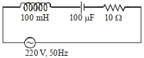
In a series $LCR$ circuit,the inductance,capacitance,and resistance are $L = 100 \, mH$,$C = 100 \, \mu F$,and $R = 10 \, \Omega$ respectively. They are connected to an $AC$ source of voltage $220 \, V$ and frequency $50 \, Hz$. The approximate value of current in the circuit will be.....$A$.
A
$27$
B
$89$
C
$55$
D
$22$
Solution
(D) Given: $L = 100 \, mH = 0.1 \, H$,$C = 100 \, \mu F = 10^{-4} \, F$,$R = 10 \, \Omega$,$V = 220 \, V$,$f = 50 \, Hz$.
Angular frequency $\omega = 2 \pi f = 2 \pi \times 50 = 100 \pi \, rad/s$.
Inductive reactance $X_L = \omega L = 100 \pi \times 0.1 = 10 \pi \approx 31.4 \, \Omega$.
Capacitive reactance $X_C = \frac{1}{\omega C} = \frac{1}{100 \pi \times 10^{-4}} = \frac{100}{\pi} \approx 31.8 \, \Omega$.
Impedance $Z = \sqrt{R^2 + (X_L - X_C)^2} = \sqrt{10^2 + (31.4 - 31.8)^2} = \sqrt{100 + (-0.4)^2} = \sqrt{100 + 0.16} \approx \sqrt{100} = 10 \, \Omega$.
Current $I = \frac{V}{Z} = \frac{220}{10} = 22 \, A$.
0 likes
View Solution71
MediumMCQ
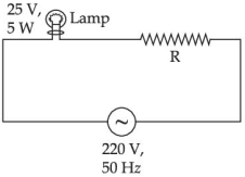
$A$ $220 \; V, 50 \; Hz$ $AC$ source is connected to a $25 \; V, 5 \; W$ lamp and an additional resistance $R$ in series (as shown in the figure) to run the lamp at its rated power. The value of $R$ (in $\Omega$) will be:
A
$975$
B
$875$
C
$775$
D
$675$
Solution
(A) The lamp is rated at $V_L = 25 \; V$ and $P_L = 5 \; W$.
The current $I$ flowing through the lamp at its rated power is given by $P_L = V_L \times I$.
$I = \frac{P_L}{V_L} = \frac{5 \; W}{25 \; V} = 0.2 \; A$.
Since the lamp and the resistance $R$ are in series,the same current $I = 0.2 \; A$ flows through the resistance $R$.
The voltage across the resistance $R$ is $V_R = V_{source} - V_L = 220 \; V - 25 \; V = 195 \; V$.
Using Ohm's law for the resistance $R$,we have $V_R = I \times R$.
$195 \; V = 0.2 \; A \times R$.
$R = \frac{195}{0.2} = 975 \; \Omega$.
0 likes
View Solution72
MediumMCQ
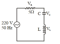
In the given circuit,the magnitudes of $V_{L}$ and $V_{C}$ are twice that of $V_{R}$. Given that $f=50\,Hz$ and $R=5\,\Omega$,the inductance of the coil is $\frac{1}{K\pi}\,mH$. The value of $K$ is:
A
$0.1$
B
$1$
C
$2$
D
$0.01$
Solution
(D) Given: $V_{L} = V_{C} = 2V_{R}$.
Since $V = IR$,we have $I X_{L} = I X_{C} = 2(IR)$.
Therefore,$X_{L} = X_{C} = 2R$.
Given $R = 5\,\Omega$,so $X_{L} = 2 \times 5 = 10\,\Omega$.
We know $X_{L} = 2\pi f L$.
Substituting the values: $10 = 2 \times \pi \times 50 \times L$.
$10 = 100 \pi L$.
$L = \frac{10}{100\pi} = \frac{1}{10\pi}\,H$.
To convert to $mH$,$L = \frac{1}{10\pi} \times 1000\,mH = \frac{100}{\pi}\,mH$.
Comparing this with $\frac{1}{K\pi}\,mH$,we have $\frac{1}{K\pi} = \frac{100}{\pi}$.
$K = \frac{1}{100} = 0.01$.
0 likes
View Solution73
DifficultMCQ
Two coils require $20 \ min$ and $60 \ min$ respectively to produce the same amount of heat energy when connected separately to the same source. If they are connected in parallel to the same source,the time required to produce the same amount of heat by the combination of coils will be . . . . . . $min$.
A
$10$
B
$15$
C
$17$
D
$14$
Solution
(B) The heat energy produced is given by $H = \frac{V^2}{R} t$. Since the heat produced $H$ and the voltage $V$ are the same for both cases,we have $H = \frac{V^2}{R_1} t_1 = \frac{V^2}{R_2} t_2$.
Given $t_1 = 20 \ min$ and $t_2 = 60 \ min$,we get $\frac{20}{R_1} = \frac{60}{R_2}$,which implies $R_2 = 3R_1$.
When connected in parallel,the equivalent resistance $R_{eq}$ is given by $\frac{1}{R_{eq}} = \frac{1}{R_1} + \frac{1}{R_2} = \frac{1}{R_1} + \frac{1}{3R_1} = \frac{4}{3R_1}$.
Thus,$R_{eq} = \frac{3R_1}{4}$.
For the same heat $H$ to be produced by the parallel combination in time $t$,we have $H = \frac{V^2}{R_{eq}} t$.
Equating this to the heat produced by the first coil: $\frac{V^2}{R_1} \times 20 = \frac{V^2}{(3R_1/4)} \times t$.
$20 = \frac{4}{3} t \Rightarrow t = \frac{20 \times 3}{4} = 15 \ min$.
0 likes
View Solution74
MediumMCQ
Consider the $L-C-R$ circuit given below. The circuit is driven by a $50 \,Hz, AC$ source with peak voltage $220 \,V$. If $R=400 \,\Omega, C=200 \,\mu F$ and $L=6 \,H$,the maximum current in the circuit is closest to ............ $A$.
A
$0.12$
B
$0.55$
C
$1.2$
D
$5.5$
Solution
(A) Given: Peak voltage $V_0 = 220 \,V$,frequency $f = 50 \,Hz$,resistance $R = 400 \,\Omega$,capacitance $C = 200 \,\mu F = 200 \times 10^{-6} \,F$,and inductance $L = 6 \,H$.
Angular frequency $\omega = 2\pi f = 2 \times \pi \times 50 = 100\pi \,rad/s$.
Inductive reactance $X_L = \omega L = 100\pi \times 6 = 600\pi \,\Omega \approx 1884.96 \,\Omega$.
Capacitive reactance $X_C = \frac{1}{\omega C} = \frac{1}{100\pi \times 200 \times 10^{-6}} = \frac{1}{0.02\pi} = \frac{50}{\pi} \,\Omega \approx 15.92 \,\Omega$.
Impedance $Z = \sqrt{R^2 + (X_L - X_C)^2} = \sqrt{400^2 + (1884.96 - 15.92)^2} = \sqrt{160000 + (1869.04)^2} \approx \sqrt{160000 + 3493310} \approx \sqrt{3653310} \approx 1911.36 \,\Omega$.
Maximum current $I_0 = \frac{V_0}{Z} = \frac{220}{1911.36} \approx 0.115 \,A$.
Rounding to the nearest value,the maximum current is approximately $0.12 \,A$.
0 likes
View Solution75
EasyMCQ
$A$ $50 \,W$ bulb connected in series with a heater coil is put to an $AC$ mains. Now the bulb is replaced by a $100 \,W$ bulb. The heater output will ...........
A
Double
B
Halve
C
Increase
D
Decrease
Solution
(C) Let the voltage of the $AC$ mains be $V$. The resistance of a bulb is given by $R_b = \frac{V_{rated}^2}{P_{rated}}$.
For a $50 \,W$ bulb,$R_1 = \frac{V_{rated}^2}{50}$.
For a $100 \,W$ bulb,$R_2 = \frac{V_{rated}^2}{100} = \frac{R_1}{2}$.
Let the resistance of the heater coil be $R_h$. The power output of the heater is $P = I^2 R_h = \left( \frac{V}{R_b + R_h} \right)^2 R_h$.
In the first case,$P_1 = \left( \frac{V}{R_1 + R_h} \right)^2 R_h$.
In the second case,$P_2 = \left( \frac{V}{R_2 + R_h} \right)^2 R_h = \left( \frac{V}{R_1/2 + R_h} \right)^2 R_h$.
Since $R_1/2 < R_1$,the denominator in the expression for $P_2$ is smaller than that for $P_1$,which implies $P_2 > P_1$.
Therefore,the heater output will increase.
0 likes
View Solution76
EasyMCQ
In an $LCR$ series circuit $R=10 \,\Omega, X_L=8 \,\Omega$ and $X_C=6 \,\Omega$. The total impedance of the circuit is ........ $\Omega$.
A
$10.2$
B
$17.2$
C
$10$
D
None of these
Solution
(A) Given: Resistance $R = 10 \,\Omega$,Inductive reactance $X_L = 8 \,\Omega$,and Capacitive reactance $X_C = 6 \,\Omega$.
The formula for the total impedance $Z$ in an $LCR$ series circuit is given by:
$Z = \sqrt{R^2 + (X_L - X_C)^2}$
Substituting the given values into the formula:
$Z = \sqrt{10^2 + (8 - 6)^2}$
$Z = \sqrt{100 + 2^2}$
$Z = \sqrt{100 + 4}$
$Z = \sqrt{104}$
$Z \approx 10.198 \,\Omega \approx 10.2 \,\Omega$.
Therefore,the total impedance is $10.2 \,\Omega$.
0 likes
View Solution77
MediumMCQ
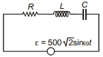
In a series $RLC$ circuit,the $r.m.s.$ voltages across the resistor and the inductor are respectively $400 \,V$ and $700 \,V$. If the equation for the applied voltage is $\varepsilon = 500 \sqrt{2} \sin \omega t$,then the peak voltage across the capacitor is ........... $V$.
A
$1200$
B
$1200 \sqrt{2}$
C
$400$
D
$400 \sqrt{2}$
Solution
(D) Given the applied voltage equation: $\varepsilon = 500 \sqrt{2} \sin \omega t$.
Comparing this with $\varepsilon = \varepsilon_0 \sin \omega t$,the peak voltage $\varepsilon_0 = 500 \sqrt{2} \,V$.
The $r.m.s.$ voltage is $\varepsilon_{rms} = \frac{\varepsilon_0}{\sqrt{2}} = \frac{500 \sqrt{2}}{\sqrt{2}} = 500 \,V$.
In a series $RLC$ circuit,the relationship between $r.m.s.$ voltages is given by $\varepsilon_{rms} = \sqrt{V_R^2 + (V_L - V_C)^2}$.
Given $V_R = 400 \,V$ and $V_L = 700 \,V$,we substitute these values:
$(500)^2 = (400)^2 + (700 - V_C)^2$
$250000 = 160000 + (700 - V_C)^2$
$(700 - V_C)^2 = 90000$
$700 - V_C = \pm 300$.
This gives two possibilities: $V_C = 700 - 300 = 400 \,V$ or $V_C = 700 + 300 = 1000 \,V$.
Assuming the standard case where $V_C = 400 \,V$ is the $r.m.s.$ voltage,the peak voltage across the capacitor is $V_{C,peak} = V_C \sqrt{2} = 400 \sqrt{2} \,V$.
0 likes
View Solution78
MediumMCQ
In the following circuit,the emf of the source is $E_0 = 200 \, V$,$R = 20 \, \Omega$,$L = 0.1 \, H$,and $C = 10.6 \, F$. If the frequency is variable,then the current at frequency $f = 0$ and $f = \infty$ is:
A
Zero,$10 \, A$
B
$10 \, A$,zero
C
$10 \, A, 10 \, A$
D
Zero,zero
Solution
(D) Given: $E_0 = 200 \, V$,$R = 20 \, \Omega$,$L = 0.1 \, H$,$C = 10.6 \, F$.
$1$. At frequency $f = 0$ ($DC$ source):
The inductive reactance is $X_L = 2 \pi f L = 0 \, \Omega$.
The capacitive reactance is $X_C = \frac{1}{2 \pi f C} = \infty$.
Since the components are in series,the total impedance $Z = \sqrt{R^2 + (X_L - X_C)^2} = \infty$.
Therefore,the current $I = \frac{E_0}{Z} = 0 \, A$.
$2$. At frequency $f = \infty$:
The inductive reactance is $X_L = 2 \pi f L = \infty$.
The capacitive reactance is $X_C = \frac{1}{2 \pi f C} = 0 \, \Omega$.
Since the components are in series,the total impedance $Z = \sqrt{R^2 + (X_L - X_C)^2} = \infty$.
Therefore,the current $I = \frac{E_0}{Z} = 0 \, A$.
Thus,in both cases,the current is zero.
0 likes
View Solution79
MediumMCQ
With an increase in the frequency of an $a.c.$ supply,the impedance of an $LCR$ series circuit:
A
Remains constant
B
Decreases
C
Increases
D
Decreases at first,becomes minimum,and then increases
Solution
(D) The impedance $Z$ of an $LCR$ series circuit is given by the formula: $Z = \sqrt{R^2 + (X_L - X_C)^2}$.
Here,$X_L = 2 \pi f L$ is the inductive reactance and $X_C = \frac{1}{2 \pi f C}$ is the capacitive reactance.
As the frequency $f$ increases,$X_L$ increases linearly,while $X_C$ decreases.
At low frequencies,$X_C$ dominates,so $Z$ decreases as $f$ increases.
At the resonant frequency $f_0 = \frac{1}{2 \pi \sqrt{LC}}$,$X_L = X_C$,making the impedance $Z = R$,which is the minimum value.
As $f$ increases beyond $f_0$,$X_L$ dominates,causing $Z$ to increase again.
Therefore,the impedance decreases at first,reaches a minimum at resonance,and then increases.
0 likes
View Solution80
MediumMCQ
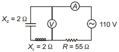
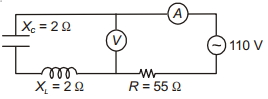
The reading of the ammeter in the circuit is ............ $A$.
A
$2$
B
$3$
C
$0$
D
$1$
Solution
(A) From the given circuit diagram, the capacitor $(X_C = 2 \, \Omega)$ and the inductor $(X_L = 2 \, \Omega)$ are connected in series with each other, and this combination is connected in parallel with the voltmeter. However, the ammeter is in series with the resistor $(R = 55 \, \Omega)$ and the $AC$ source $(110 \, V)$.
Since the capacitor and inductor are in series, their net reactance is $X = X_L - X_C = 2 \, \Omega - 2 \, \Omega = 0 \, \Omega$.
This means the branch containing the capacitor and inductor acts as a short circuit (zero impedance) for the $AC$ source.
Therefore, the entire voltage of the source $(110 \, V)$ appears across the resistor $(R = 55 \, \Omega)$.
The current $I$ measured by the ammeter is given by Ohm's law:
$I = \frac{V}{R} = \frac{110 \, V}{55 \, \Omega} = 2 \, A$.
0 likes
View Solution81
EasyMCQ
In the given $A.C.$ circuit,the instantaneous currents through the inductor and capacitor are $0.8 \,A$ and $0.4 \,A$ respectively. The instantaneous current through the resistor is:
A
$1.2 \,A$
B
$0.6 \,A$
C
$0.4 \,A$
D
$\sqrt{0.8} \,A$
Solution
(C) In the given circuit,the resistor $R$ is in series with a parallel combination of the inductor $L$ and the capacitor $C$.
The current flowing through the resistor $I_R$ is the total current supplied by the source.
In a parallel $LC$ circuit,the currents through the inductor $(i_L)$ and the capacitor $(i_C)$ are $180^{\circ}$ out of phase with each other.
Therefore,the net current through the parallel $LC$ combination is given by the difference between the magnitudes of the currents through the inductor and the capacitor:
$I_{LC} = |i_L - i_C|$
Given $i_L = 0.8 \,A$ and $i_C = 0.4 \,A$:
$I_{LC} = |0.8 \,A - 0.4 \,A| = 0.4 \,A$
Since the resistor is in series with this parallel combination,the current through the resistor $I_R$ must be equal to the net current flowing through the $LC$ branch.
Thus,$I_R = 0.4 \,A$.
Therefore,the correct option is $C$.
0 likes
View Solution82
MediumMCQ
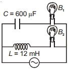
In the circuit shown in the figure,if both the bulbs $B_1$ and $B_2$ are identical,then:
A
Both bulbs have equal brightness.
B
$B_2$ will be brighter than $B_1$.
C
As the frequency is increased,the brightness of $B_1$ will increase and that of $B_2$ will decrease.
D
As the frequency is decreased,the brightness of $B_1$ will increase and that of $B_2$ will decrease.
Solution
(C) The bulb $B_1$ is in series with a capacitor $C$,and the bulb $B_2$ is in series with an inductor $L$.
The capacitive reactance is given by $X_C = \frac{1}{2\pi f C}$,which decreases as frequency $f$ increases.
The inductive reactance is given by $X_L = 2\pi f L$,which increases as frequency $f$ increases.
As the frequency $f$ increases,$X_C$ decreases,allowing more current to flow through the branch containing $B_1$,thus increasing its brightness.
Conversely,as $f$ increases,$X_L$ increases,reducing the current through the branch containing $B_2$,thus decreasing its brightness.
Therefore,option $(c)$ is correct.
0 likes
View Solution83
MediumMCQ
$A$ series $LCR$ circuit consists of an inductor $L$,a capacitor $C$,and a resistor $R$ connected across a source of emf $\varepsilon = \varepsilon_0 \sin \omega t$. When $\omega L = \frac{1}{\omega C}$,the current in the circuit is $I_0$. If the angular frequency of the source is changed to $\omega^{\prime}$,the current in the circuit becomes $\frac{I_0}{2}$. Then,the value of $\left|\omega^{\prime} L - \frac{1}{\omega^{\prime} C}\right|$ is
A
$R$
B
$\sqrt{3} R$
C
$\sqrt{15} R$
D
$0$
Solution
(B) At resonance,$\omega L = \frac{1}{\omega C}$,the impedance of the circuit is $Z = R$. Therefore,the current is $I_0 = \frac{\varepsilon_0}{R}$.
When the angular frequency is changed to $\omega^{\prime}$,the new current is $I^{\prime} = \frac{I_0}{2} = \frac{\varepsilon_0}{2R}$.
The impedance at frequency $\omega^{\prime}$ is given by $Z^{\prime} = \sqrt{R^2 + \left(\omega^{\prime} L - \frac{1}{\omega^{\prime} C}\right)^2}$.
Since $I^{\prime} = \frac{\varepsilon_0}{Z^{\prime}}$,we have $\frac{\varepsilon_0}{2R} = \frac{\varepsilon_0}{\sqrt{R^2 + \left(\omega^{\prime} L - \frac{1}{\omega^{\prime} C}\right)^2}}$.
Squaring both sides,we get $4R^2 = R^2 + \left(\omega^{\prime} L - \frac{1}{\omega^{\prime} C}\right)^2$.
Rearranging the terms,$\left(\omega^{\prime} L - \frac{1}{\omega^{\prime} C}\right)^2 = 3R^2$.
Taking the square root,we find $\left|\omega^{\prime} L - \frac{1}{\omega^{\prime} C}\right| = \sqrt{3} R$.
0 likes
View Solution84
MediumMCQ
For the given figures,choose the correct option:
A
The rms current in circuit $(b)$ can never be larger than that in $(a)$.
B
The rms current in figure $(a)$ is always equal to that in figure $(b)$.
C
The rms current in circuit $(b)$ can be larger than that in $(a)$.
D
At resonance,current in $(b)$ is less than that in $(a)$.
Solution
(A) In circuit $(a)$,the impedance is $Z_a = R = 40\,\Omega$. The rms current is $I_a = \frac{V}{Z_a} = \frac{220}{40} = 5.5\,A$.
In circuit $(b)$,the impedance is $Z_b = \sqrt{R^2 + (X_L - X_C)^2}$.
Since $Z_b = \sqrt{R^2 + (X_L - X_C)^2} \geq R$,it follows that $Z_b \geq Z_a$.
Therefore,the current $I_b = \frac{V}{Z_b} \leq \frac{V}{Z_a} = I_a$.
This means the rms current in circuit $(b)$ can never be larger than the rms current in circuit $(a)$.
0 likes
View Solution85
MediumMCQ
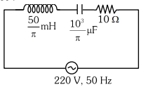
The net impedance of the circuit (as shown in the figure) will be $...........\,\Omega$.
A
$15$
B
$10 \sqrt{2}$
C
$25$
D
$5 \sqrt{5}$
Solution
(D) Given: Inductance $L = \frac{50}{\pi} \text{ mH} = \frac{50}{\pi} \times 10^{-3} \text{ H}$,Capacitance $C = \frac{10^3}{\pi} \text{ }\mu\text{F} = \frac{10^3}{\pi} \times 10^{-6} \text{ F}$,Resistance $R = 10 \,\Omega$,Frequency $f = 50 \text{ Hz}$.
First,calculate the inductive reactance $X_L$:
$X_L = 2 \pi f L = 2 \pi \times 50 \times \left( \frac{50}{\pi} \times 10^{-3} \right) = 100 \times 50 \times 10^{-3} = 5 \,\Omega$.
Next,calculate the capacitive reactance $X_C$:
$X_C = \frac{1}{2 \pi f C} = \frac{1}{2 \pi \times 50 \times \left( \frac{10^3}{\pi} \times 10^{-6} \right)} = \frac{1}{100 \times 10^{-3}} = \frac{1}{0.1} = 10 \,\Omega$.
The net impedance $Z$ of the $LCR$ series circuit is given by:
$Z = \sqrt{R^2 + (X_L - X_C)^2}$
$Z = \sqrt{10^2 + (5 - 10)^2}$
$Z = \sqrt{100 + (-5)^2} = \sqrt{100 + 25} = \sqrt{125}$
$Z = 5 \sqrt{5} \,\Omega$.
0 likes
View Solution86
DifficultMCQ
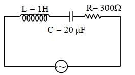
An $AC$ source is connected in the given series $LCR$ circuit. The $RMS$ potential difference across the capacitor of $20 \mu F$ is . . . . . . $V$.
$V = 50 \sqrt{2} \sin 100 t$ volt
$V = 50 \sqrt{2} \sin 100 t$ volt
A
$20$
B
$30$
C
$40$
D
$50$
Solution
(D) Given: $L = 1 \text{ H}$,$C = 20 \mu F = 20 \times 10^{-6} \text{ F}$,$R = 300 \Omega$,$V = 50 \sqrt{2} \sin 100 t$.
$1$. The angular frequency $\omega = 100 \text{ rad/s}$.
$2$. The $RMS$ voltage $V_{\text{rms}} = \frac{V_0}{\sqrt{2}} = \frac{50 \sqrt{2}}{\sqrt{2}} = 50 \text{ V}$.
$3$. Inductive reactance $X_L = \omega L = 100 \times 1 = 100 \Omega$.
$4$. Capacitive reactance $X_C = \frac{1}{\omega C} = \frac{1}{100 \times 20 \times 10^{-6}} = \frac{1}{2 \times 10^{-3}} = 500 \Omega$.
$5$. Impedance $Z = \sqrt{R^2 + (X_L - X_C)^2} = \sqrt{300^2 + (100 - 500)^2} = \sqrt{300^2 + (-400)^2} = \sqrt{90000 + 160000} = \sqrt{250000} = 500 \Omega$.
$6$. $RMS$ current $I_{\text{rms}} = \frac{V_{\text{rms}}}{Z} = \frac{50}{500} = 0.1 \text{ A}$.
$7$. $RMS$ potential difference across the capacitor $V_C = I_{\text{rms}} \times X_C = 0.1 \times 500 = 50 \text{ V}$.
0 likes
View Solution87
AdvancedMCQ
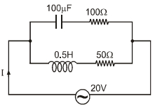
In the given circuit,the $AC$ source has $\omega = 100 \ rad/s$. Considering the inductor and capacitor to be ideal,the correct choice$(s)$ is(are):
$(A)$ The current through the circuit,$I$ is $0.3 \ A$
$(B)$ The current through the circuit,$I$ is $0.3 \sqrt{2} \ A$
$(C)$ The voltage across $100 \ \Omega$ resistor $= 10 \sqrt{2} \ V$
$(D)$ The voltage across $50 \ \Omega$ resistor $= 10 \sqrt{2} \ V$
$(A)$ The current through the circuit,$I$ is $0.3 \ A$
$(B)$ The current through the circuit,$I$ is $0.3 \sqrt{2} \ A$
$(C)$ The voltage across $100 \ \Omega$ resistor $= 10 \sqrt{2} \ V$
$(D)$ The voltage across $50 \ \Omega$ resistor $= 10 \sqrt{2} \ V$
A
$(A, C)$
B
$(A, B)$
C
$(A, D)$
D
$(B, D)$
Solution
(A, C, D) Given: $V_{rms} = 20 \ V$,$\omega = 100 \ rad/s$,$C = 100 \ \mu F$,$L = 0.5 \ H$.
$1$. Impedance of the upper branch ($RC$ series):
$X_C = \frac{1}{\omega C} = \frac{1}{100 \times 100 \times 10^{-6}} = 100 \ \Omega$.
$Z_1 = \sqrt{R_1^2 + X_C^2} = \sqrt{100^2 + 100^2} = 100\sqrt{2} \ \Omega$.
$I_{1,rms} = \frac{V_{rms}}{Z_1} = \frac{20}{100\sqrt{2}} = \frac{1}{5\sqrt{2}} \ A$.
Voltage across $100 \ \Omega$ resistor: $V_{R1} = I_{1,rms} \times R_1 = \frac{1}{5\sqrt{2}} \times 100 = \frac{20}{\sqrt{2}} = 10\sqrt{2} \ V$. (Option $C$ is correct).
$2$. Impedance of the lower branch ($RL$ series):
$X_L = \omega L = 100 \times 0.5 = 50 \ \Omega$.
$Z_2 = \sqrt{R_2^2 + X_L^2} = \sqrt{50^2 + 50^2} = 50\sqrt{2} \ \Omega$.
$I_{2,rms} = \frac{V_{rms}}{Z_2} = \frac{20}{50\sqrt{2}} = \frac{2}{5\sqrt{2}} \ A$.
Voltage across $50 \ \Omega$ resistor: $V_{R2} = I_{2,rms} \times R_2 = \frac{2}{5\sqrt{2}} \times 50 = \frac{20}{\sqrt{2}} = 10\sqrt{2} \ V$. (Option $D$ is correct).
$3$. Total current $I_{rms}$:
The phase angle $\phi_1 = \tan^{-1}(\frac{-X_C}{R_1}) = -45^\circ$ and $\phi_2 = \tan^{-1}(\frac{X_L}{R_2}) = 45^\circ$.
The phase difference between $I_1$ and $I_2$ is $90^\circ$.
$I_{rms} = \sqrt{I_{1,rms}^2 + I_{2,rms}^2} = \sqrt{(\frac{1}{5\sqrt{2}})^2 + (\frac{2}{5\sqrt{2}})^2} = \sqrt{\frac{1}{50} + \frac{4}{50}} = \sqrt{\frac{5}{50}} = \frac{1}{\sqrt{10}} \approx 0.316 \ A \approx 0.3 \ A$. (Option $A$ is correct).
0 likes
View Solution88
MediumMCQ
An inductor of reactance $100 \ \Omega$, a capacitor of reactance $50 \ \Omega$, and a resistor of resistance $50 \ \Omega$ are connected in series with an $AC$ source of $10 \ V, 50 \ Hz$. Average power dissipated by the circuit is . . . . . . $W$.
A
$8$
B
$1$
C
$9$
D
$2$
Solution
(B) The impedance $Z$ of an $LCR$ series circuit is given by $Z = \sqrt{R^2 + (X_L - X_C)^2}$.
Given $R = 50 \ \Omega$, $X_L = 100 \ \Omega$, and $X_C = 50 \ \Omega$.
$Z = \sqrt{50^2 + (100 - 50)^2} = \sqrt{50^2 + 50^2} = \sqrt{2500 + 2500} = \sqrt{5000} = 50\sqrt{2} \ \Omega$.
The average power dissipated in an $AC$ circuit is $P = V_{rms} I_{rms} \cos \phi$, where $\cos \phi = \frac{R}{Z}$ is the power factor.
$P = V_{rms} \times \left( \frac{V_{rms}}{Z} \right) \times \left( \frac{R}{Z} \right) = \frac{V_{rms}^2 R}{Z^2}$.
Given $V_{rms} = 10 \ V$.
$P = \frac{10^2 \times 50}{(50\sqrt{2})^2} = \frac{100 \times 50}{2500 \times 2} = \frac{5000}{5000} = 1 \ W$.
0 likes
View Solution89
MediumMCQ
To an $AC$ power supply of $220 \ V$ at $50 \ Hz$,a resistor of $20 \ \Omega$,a capacitor of reactance $25 \ \Omega$,and an inductor of reactance $45 \ \Omega$ are connected in series. The corresponding current in the circuit and the phase angle between the current and the voltage are,respectively:
A
$7.8 \ A$ and $30^{\circ}$
B
$7.8 \ A$ and $45^{\circ}$
C
$15.6 \ A$ and $30^{\circ}$
D
$15.6 \ A$ and $45^{\circ}$
Solution
(B) Given: $V_{rms} = 220 \ V$,$R = 20 \ \Omega$,$X_C = 25 \ \Omega$,$X_L = 45 \ \Omega$.
The impedance $Z$ of the $LCR$ series circuit is given by $Z = \sqrt{R^2 + (X_L - X_C)^2}$.
Substituting the values: $Z = \sqrt{20^2 + (45 - 25)^2} = \sqrt{400 + 20^2} = \sqrt{400 + 400} = \sqrt{800} = 20\sqrt{2} \ \Omega$.
The $RMS$ current $I_{rms}$ is $I_{rms} = \frac{V_{rms}}{Z} = \frac{220}{20\sqrt{2}} = \frac{11}{\sqrt{2}} \approx 7.778 \ A \approx 7.8 \ A$.
The phase angle $\phi$ is given by $\tan \phi = \frac{X_L - X_C}{R}$.
Substituting the values: $\tan \phi = \frac{45 - 25}{20} = \frac{20}{20} = 1$.
Therefore,$\phi = \tan^{-1}(1) = 45^{\circ}$.
0 likes
View Solution90
EasyMCQ
For a series $LCR$ circuit,which of the following statements is correct?
A
Applied $e.m.f.$ and potential difference across the resistance are in the same phase.
B
Applied $e.m.f.$ and potential difference across the inductor coil have a phase difference of $\pi / 2$.
C
Potential difference across the capacitor and the inductor have a phase difference of $\pi / 2$.
D
Potential difference across the resistance and the capacitor have a phase difference of $\pi / 2$.
Solution
(D) In a series $LCR$ circuit,the current $I$ is the same through all components.
$1$. The potential difference across the resistor $(V_R)$ is in phase with the current $I$.
$2$. The potential difference across the inductor $(V_L)$ leads the current $I$ by $\pi / 2$.
$3$. The potential difference across the capacitor $(V_C)$ lags behind the current $I$ by $\pi / 2$.
Since $V_L$ is at $+\pi / 2$ relative to $I$ and $V_C$ is at $-\pi / 2$ relative to $I$,the phase difference between $V_L$ and $V_C$ is $\pi / 2 - (-\pi / 2) = \pi$.
Option $A$ states that the applied $e.m.f.$ and potential difference across the resistance are in the same phase,which is incorrect as the applied $e.m.f.$ $V$ is generally at an angle $\theta$ with $I$ (and $V_R$).
Option $B$ is incorrect because the phase difference between applied $e.m.f.$ and $V_L$ depends on the circuit parameters.
Option $C$ is incorrect because the phase difference between $V_L$ and $V_C$ is $\pi$.
Option $D$ is correct because $V_R$ is in phase with $I$ and $V_C$ is at $\pi / 2$ phase difference with $I$,so the phase difference between $V_R$ and $V_C$ is $\pi / 2$.
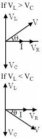
0 likes
View Solution91
EasyMCQ
When a capacitor is connected in series with an $LR$ circuit,the alternating current flowing in the circuit
A
remains constant
B
increases
C
decreases
D
is zero
Solution
(B) In an $LR$ circuit,the impedance is given by $Z = \sqrt{R^2 + X_L^2}$,where $X_L = \omega L$ is the inductive reactance.
When a capacitor is connected in series,the circuit becomes an $LCR$ circuit.
The new impedance of the $LCR$ circuit is given by $Z' = \sqrt{R^2 + (X_L - X_C)^2}$,where $X_C = \frac{1}{\omega C}$ is the capacitive reactance.
If the circuit was initially inductive ($X_L > X_C$ or $X_L$ is present),adding a capacitor introduces $X_C$,which partially cancels the effect of $X_L$ if $X_L > X_C$,thereby reducing the total impedance $Z$.
Since the current $I = \frac{V}{Z}$,a decrease in impedance $Z$ leads to an increase in the current $I$ flowing through the circuit.
0 likes
View Solution92
MediumMCQ
The figure shows a combination of inductances and capacitances. The resonant frequency of the $L-C$ circuit is:
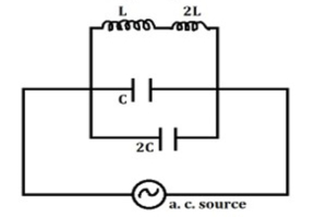
A
$\frac{1}{2 \pi \sqrt{LC}}$
B
$\frac{1}{3 \pi \sqrt{LC}}$
C
$\frac{1}{4 \pi \sqrt{LC}}$
D
$\frac{1}{6 \pi \sqrt{LC}}$
Solution
(D) In the given circuit,the two inductors $L$ and $2L$ are connected in series. Therefore,the equivalent inductance $L_{eq}$ is given by:
$L_{eq} = L + 2L = 3L$
The two capacitors $C$ and $2C$ are connected in parallel. Therefore,the equivalent capacitance $C_{eq}$ is given by:
$C_{eq} = C + 2C = 3C$
The resonant frequency $f$ of an $L-C$ circuit is given by the formula:
$f = \frac{1}{2 \pi \sqrt{L_{eq} C_{eq}}}$
Substituting the values of $L_{eq}$ and $C_{eq}$ into the formula:
$f = \frac{1}{2 \pi \sqrt{(3L)(3C)}}$
$f = \frac{1}{2 \pi \sqrt{9LC}}$
$f = \frac{1}{2 \pi \cdot 3 \sqrt{LC}}$
$f = \frac{1}{6 \pi \sqrt{LC}}$
0 likes
View Solution93
MediumMCQ
The value of alternating e.m.f. $(E)$ in the given circuit is (in $V$)
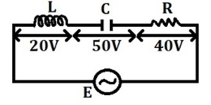
A
$30$
B
$60$
C
$50$
D
$110$
Solution
(C) In a series $LCR$ circuit,the applied alternating e.m.f. $(E)$ is given by the phasor sum of the individual potential drops across the inductor $(V_L)$,capacitor $(V_C)$,and resistor $(V_R)$.
The formula for the total e.m.f. is:
$E = \sqrt{V_R^2 + (V_L - V_C)^2}$
Given values from the circuit diagram:
$V_L = 20 \ V$
$V_C = 50 \ V$
$V_R = 40 \ V$
Substituting these values into the formula:
$E = \sqrt{40^2 + (20 - 50)^2}$
$E = \sqrt{1600 + (-30)^2}$
$E = \sqrt{1600 + 900}$
$E = \sqrt{2500}$
$E = 50 \ V$
Therefore,the value of the alternating e.m.f. is $50 \ V$.
0 likes
View Solution94
EasyMCQ
For the given figure,choose the correct option.
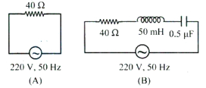
A
The r.m.s. current in circuit $(B)$ can never be greater than that in circuit $(A)$.
B
The r.m.s. current in circuit $(A)$ is always equal to that in circuit $(B)$.
C
The r.m.s. current in circuit $(B)$ can be greater than in circuit $(A)$.
D
At resonance,current in $(B)$ is less than that in circuit $(A)$.
Solution
(A) In circuit $(A)$,the impedance is $Z_A = R = 40 \ \Omega$.
In circuit $(B)$,the impedance is $Z_B = \sqrt{R^2 + (X_L - X_C)^2}$.
Since $Z_B = \sqrt{R^2 + (X_L - X_C)^2} \ge R$,it follows that $Z_B \ge Z_A$.
The r.m.s. current is given by $I = V/Z$. Since the voltage $V$ is the same $(220 \ V)$ for both circuits,$I_B = V/Z_B$ and $I_A = V/Z_A$.
Since $Z_B \ge Z_A$,it implies $I_B \le I_A$. Thus,the r.m.s. current in circuit $(B)$ can never be greater than that in circuit $(A)$.
0 likes
View Solution95
EasyMCQ
In a series $LCR$ circuit,$R$ represents the resistance of an electric bulb. If the frequency of the $A.C.$ supply is doubled,what should be the values of inductance $L$ and capacitance $C$ to maintain the same current?
A
both doubled.
B
made four times.
C
made eight times.
D
both halved simultaneously.
Solution
(D) In a series $LCR$ circuit,the current $I$ is given by $I = \frac{E}{Z} = \frac{E}{\sqrt{R^2 + (X_L - X_C)^2}}$.
Here,$X_L = 2 \pi f L$ and $X_C = \frac{1}{2 \pi f C}$.
To keep the current $I$ constant for a given voltage $E$ and resistance $R$,the impedance $Z$ must remain constant.
This requires the reactances $X_L$ and $X_C$ to remain unchanged.
If the frequency $f$ is doubled $(f' = 2f)$,then for $X_L$ to remain constant: $2 \pi (2f) L' = 2 \pi f L \implies L' = \frac{L}{2}$.
Similarly,for $X_C$ to remain constant: $\frac{1}{2 \pi (2f) C'} = \frac{1}{2 \pi f C} \implies C' = \frac{C}{2}$.
Therefore,both $L$ and $C$ should be halved simultaneously.
0 likes
View Solution96
MediumMCQ
An inductance of $\frac{300}{\pi} \text{ mH}$,a capacitance of $\frac{1}{\pi} \text{ mF}$ and a resistance of $20 \ \Omega$ are connected in series with an a.c. source of $240 \text{ V}, 50 \text{ Hz}$. The phase angle of the circuit is
A
$\tan^{-1}(0)$
B
$\tan^{-1}\left(\frac{1}{\sqrt{3}}\right)$
C
$\tan^{-1}(1)$
D
$\tan^{-1}(\sqrt{3})$
Solution
(C) The phase angle $\phi$ in an $LCR$ series circuit is given by $\tan \phi = \frac{X_L - X_C}{R}$.
Given: $L = \frac{300}{\pi} \text{ mH} = \frac{0.3}{\pi} \text{ H}$,$C = \frac{1}{\pi} \text{ mF} = \frac{1}{\pi} \times 10^{-3} \text{ F}$,$R = 20 \ \Omega$,$f = 50 \text{ Hz}$.
Angular frequency $\omega = 2 \pi f = 2 \times \pi \times 50 = 100 \pi \text{ rad/s}$.
Inductive reactance $X_L = \omega L = 100 \pi \times \frac{0.3}{\pi} = 30 \ \Omega$.
Capacitive reactance $X_C = \frac{1}{\omega C} = \frac{1}{100 \pi \times \frac{1}{\pi} \times 10^{-3}} = \frac{1}{0.1} = 10 \ \Omega$.
Substituting these values into the formula:
$\tan \phi = \frac{30 - 10}{20} = \frac{20}{20} = 1$.
Therefore,$\phi = \tan^{-1}(1)$.
0 likes
View Solution97
MediumMCQ
Which one of the following graphs correctly represents the variation of impedance $(Z)$ of a series $LCR$ circuit with the frequency $(v)$ of the applied $a.c.$?
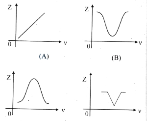
A
$(A)$
B
$(B)$
C
$(C)$
D
$(D)$
Solution
(B) The impedance $Z$ of a series $LCR$ circuit is given by the formula: $Z = \sqrt{R^2 + (2 \pi v L - \frac{1}{2 \pi v C})^2}$.
At very low frequencies $(v \to 0)$,the capacitive reactance $X_C = \frac{1}{2 \pi v C}$ approaches infinity,so $Z \to \infty$.
At the resonant frequency $v_r = \frac{1}{2 \pi \sqrt{LC}}$,the inductive reactance $X_L$ equals the capacitive reactance $X_C$,making the net reactance zero. Thus,$Z = R$,which is the minimum value of impedance.
For frequencies higher than the resonant frequency $(v > v_r)$,the inductive reactance $X_L = 2 \pi v L$ dominates,and $Z$ increases as $v$ increases.
Therefore,the graph of $Z$ versus $v$ starts from a high value,decreases to a minimum value $R$ at $v_r$,and then increases again. This behavior is correctly represented by graph $(B)$.
0 likes
View Solution98
MediumMCQ
An alternating voltage of frequency $\omega$ is induced in an electric circuit consisting of an inductance $L$ and capacitance $C$,connected in parallel. Then across the inductance coil:
A
current is maximum when $\omega^2 = \frac{1}{LC}$
B
current is zero
C
voltage is minimum when $\omega^2 = \frac{1}{LC}$
D
voltage is maximum when $\omega^2 = \frac{1}{LC}$
Solution
(D) In a parallel $LC$ circuit,the total impedance $Z$ is given by $\frac{1}{Z} = \sqrt{(\frac{1}{X_L} - \frac{1}{X_C})^2}$.
At resonance,$\omega^2 = \frac{1}{LC}$,which implies $X_L = X_C$.
At this frequency,the net current drawn from the source is minimum because the impedance $Z$ becomes infinite.
Since the circuit is connected in parallel,the voltage across the inductance $L$ and capacitance $C$ is the same as the source voltage.
However,in a parallel $LC$ circuit at resonance,the circulating current between $L$ and $C$ is maximum,leading to maximum voltage across the components.
0 likes
View Solution99
EasyMCQ
With an increase in the frequency of an $A.C.$ supply,the impedance of an $L-C-R$ series circuit
A
remains constant.
B
increases.
C
decreases.
D
decreases at first,becomes minimum,and then increases.
Solution
(D) The impedance $Z$ of an $L-C-R$ series circuit is given by $Z = \sqrt{R^2 + (X_L - X_C)^2}$.
Here,$X_L = L\omega = 2\pi fL$ and $X_C = \frac{1}{C\omega} = \frac{1}{2\pi fC}$.
As the frequency $f$ increases,the inductive reactance $X_L$ increases linearly,while the capacitive reactance $X_C$ decreases.
At low frequencies,$X_C$ dominates,so $Z$ decreases as $f$ increases.
At the resonant frequency $f_0 = \frac{1}{2\pi\sqrt{LC}}$,$X_L = X_C$,making the impedance $Z = R$,which is the minimum value.
As $f$ increases beyond $f_0$,$X_L$ dominates,causing $Z$ to increase.
Therefore,the impedance decreases at first,reaches a minimum value,and then increases.
0 likes
View SolutionAlternating Current — Inductance, Capacitance and Resistance in Series and Parallel · Frequently Asked Questions
1Are these Alternating Current questions useful for JEE and NEET?
Yes. All questions in this section are mapped to JEE Main and NEET exam patterns. Previous year questions from JEE Main, NEET, GUJCET and state-level exams are included with full solutions.
2Can I switch to Hindi or Gujarati for these questions?
Yes. Use the language tabs in the hero section or the sidebar to view the same questions and solutions in English, Hindi or Gujarati.
3How do I generate a question paper from this subtopic?
Use the Vedclass Exam Paper Generator — select the chapter and subtopic, set difficulty, and generate Sets A, B, C, D automatically. First 3 chapters of every subject are free.
Vedclass Products
For Students
Vedclass Test Series
Mock tests in real JEE/NEET style with performance analysis. 5-day free trial.
Start Free TrialFor Teachers
Exam Paper Generator
Generate Set A/B/C/D papers from this chapter in 2 minutes. 3 chapters free.
Try FreeFor Institutes
Online Exam Module
Live online exams with unlimited students, 360° analytics & white-label branding.
See DemoFor Teachers & Institutes
Generate a Alternating Current Exam Paper in 2 Minutes
Select subtopic & difficulty — Sets A, B, C, D auto-generated with No Repeat logic.
First 3 chapters of every subject are free — no payment required.