
A English
Inductance, Capacitance and Resistance in Series and Parallel Questions in English
Class 12 Physics · Alternating Current · Inductance, Capacitance and Resistance in Series and Parallel
138+
Questions
English
Language
100%
With Solutions
Showing 38 of 138 questions in English
101
EasyMCQ
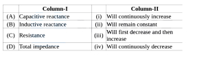
In an $LCR$ series circuit,if the angular frequency $\omega$ is gradually increased,then match the following columns:
| Column-$I$ | Column-$II$ |
|---|---|
| $(A)$ Capacitive reactance | $(i)$ Will continuously increase |
| $(B)$ Inductive reactance | (ii) Will remain constant |
| $(C)$ Resistance | (iii) Will first decrease and then increase |
| $(D)$ Total impedance | (iv) Will continuously decrease |
A
$(A)-(iv), (B)-(i), (C)-(ii), (D)-(iii)$
B
$(A)-(i), (B)-(iii), (C)-(iv), (D)-(ii)$
C
$(A)-(ii), (B)-(iii), (C)-(i), (D)-(iv)$
D
$(A)-(i), (B)-(iv), (C)-(ii), (D)-(iii)$
Solution
(A) The capacitive reactance is given by $X_C = \frac{1}{\omega C}$. As $\omega$ increases,$X_C$ decreases continuously. Therefore,$(A)-(iv)$.
The inductive reactance is given by $X_L = \omega L$. As $\omega$ increases,$X_L$ increases continuously. Therefore,$(B)-(i)$.
The resistance $R$ is independent of the angular frequency $\omega$. Therefore,$(C)-(ii)$.
The total impedance $Z$ in an $LCR$ series circuit is given by $Z = \sqrt{R^2 + (X_L - X_C)^2}$. At resonance,$X_L = X_C$,so $Z$ is minimum. As $\omega$ increases from zero,$Z$ first decreases until resonance and then increases. Therefore,$(D)-(iii)$.
0 likes
View Solution102
EasyMCQ
In a series $LCR$ circuit, the voltages across $L, C$, and $R$ are $50 \,V, 20 \,V$, and $40 \,V$ respectively. The $A.C.$ voltage applied across the combination of $LCR$ is: (in $\,V$)
A
$10$
B
$110$
C
$70$
D
$50$
Solution
(D) In a series $LCR$ circuit, the total applied voltage $V$ is the phasor sum of the voltages across the individual components.
The formula for the total voltage is given by:
$V = \sqrt{V_R^2 + (V_L - V_C)^2}$
Given:
$V_L = 50 \,V$
$V_C = 20 \,V$
$V_R = 40 \,V$
Substituting these values into the formula:
$V = \sqrt{40^2 + (50 - 20)^2}$
$V = \sqrt{1600 + (30)^2}$
$V = \sqrt{1600 + 900}$
$V = \sqrt{2500}$
$V = 50 \,V$
Therefore, the applied $A.C.$ voltage is $50 \,V$.
0 likes
View Solution103
MediumMCQ
When a capacitor is connected in a series $LR$ circuit,what happens to the alternating current flowing in the circuit?
A
remains constant.
B
increases.
C
decreases.
D
becomes zero.
Solution
(B) The impedance of a series $LR$ circuit is given by $Z_1 = \sqrt{R^2 + X_L^2}$.
When a capacitor is connected in series with this circuit,the new impedance becomes $Z_2 = \sqrt{R^2 + (X_L - X_C)^2}$.
Since $(X_L - X_C)^2 < X_L^2$ (assuming $X_C$ is not zero),the new impedance $Z_2$ is less than the original impedance $Z_1$.
According to Ohm's law for $AC$ circuits,$I = \frac{V}{Z}$.
Since the impedance $Z$ decreases,the current $I$ flowing in the circuit increases.
0 likes
View Solution104
DifficultMCQ
An inductor coil takes a current of $8 \, A$ when connected to a $100 \, V$ and $50 \, Hz$ $AC$ source. $A$ pure resistor under the same condition takes a current of $10 \, A$. If the inductor coil and resistor are connected in series to a $100 \, V$ and $40 \, Hz$ $AC$ supply, then the current in the series combination of the above resistor and inductor is:
A
$\frac{10}{\sqrt{3}} \, A$
B
$\frac{5}{\sqrt{2}} \, A$
C
$10 \sqrt{2} \, A$
D
$5 \sqrt{2} \, A$
Solution
(D) For the inductor coil at $50 \, Hz$:
$X_L = \frac{V}{I} = \frac{100}{8} = 12.5 \, \Omega$.
For the resistor:
$R = \frac{V}{I} = \frac{100}{10} = 10 \, \Omega$.
At the new frequency $f' = 40 \, Hz$, the new inductive reactance $X_L'$ is:
$X_L' = X_L \times \frac{f'}{f} = 12.5 \times \frac{40}{50} = 10 \, \Omega$.
When connected in series, the impedance $Z$ is:
$Z = \sqrt{R^2 + (X_L')^2} = \sqrt{10^2 + 10^2} = 10\sqrt{2} \, \Omega$.
The current $I$ in the series circuit is:
$I = \frac{V}{Z} = \frac{100}{10\sqrt{2}} = \frac{10}{\sqrt{2}} = 5\sqrt{2} \, A$.
0 likes
View Solution105
MediumMCQ
In a series $LCR$ circuit,the resistance is $18 \ \Omega$ and the impedance is $33 \ \Omega$. An $r.m.s.$ voltage of $220 \ V$ is applied across the circuit. The true power consumed in the $a.c.$ circuit is: (in $W$)
A
$400$
B
$600$
C
$800$
D
$200$
Solution
(C) The $r.m.s.$ current $I$ in the circuit is given by $I = \frac{V}{Z}$.
Given $V = 220 \ V$ and $Z = 33 \ \Omega$,we have $I = \frac{220}{33} = \frac{20}{3} \ A$.
The true power $P$ consumed in an $a.c.$ circuit is given by $P = I^2 R$.
Substituting the values,$P = \left(\frac{20}{3}\right)^2 \times 18$.
$P = \frac{400}{9} \times 18 = 400 \times 2 = 800 \ W$.
Given $V = 220 \ V$ and $Z = 33 \ \Omega$,we have $I = \frac{220}{33} = \frac{20}{3} \ A$.
The true power $P$ consumed in an $a.c.$ circuit is given by $P = I^2 R$.
Substituting the values,$P = \left(\frac{20}{3}\right)^2 \times 18$.
$P = \frac{400}{9} \times 18 = 400 \times 2 = 800 \ W$.
0 likes
View Solution106
MediumMCQ
$A$ series $LCR$ circuit has $R=200 \Omega$, $L=663 \text{ mH}$, and $C=26.5 \mu F$. The applied alternating voltage has an amplitude of $50 \text{ V}$ and a frequency of $60 \text{ Hz}$ such that $X_{L}=250 \Omega$ and $X_{C}=100 \Omega$. The peak current is: (in $\text{ A}$)
A
$0.33$
B
$0.20$
C
$0.50$
D
$0.25$
Solution
(B) Given: $R=200 \Omega$, $L=663 \text{ mH}$, $C=26.5 \mu F$, $V_{0}=50 \text{ V}$, $X_{L}=250 \Omega$, $X_{C}=100 \Omega$.
The impedance $Z$ of a series $LCR$ circuit is given by $Z = \sqrt{R^{2} + (X_{L} - X_{C})^{2}}$.
Substituting the values: $Z = \sqrt{200^{2} + (250 - 100)^{2}} = \sqrt{40000 + 150^{2}}$.
$Z = \sqrt{40000 + 22500} = \sqrt{62500} = 250 \Omega$.
The peak current $i_{0}$ is given by $i_{0} = \frac{V_{0}}{Z}$.
$i_{0} = \frac{50}{250} = 0.2 \text{ A}$.
0 likes
View Solution107
MediumMCQ
In an $LCR$ series circuit,$R = 18 \ \Omega$ and the impedance $Z = 33 \ \Omega$. An $r.m.s.$ voltage of $V_{rms} = 220 \ V$ is applied across the circuit. The true power consumed in the $a.c.$ circuit is: (in $W$)
A
$400$
B
$600$
C
$800$
D
$900$
Solution
(C) The true power $P$ consumed in an $LCR$ series circuit is given by the formula: $P = V_{rms} \cdot I_{rms} \cdot \cos \phi$,where $\cos \phi$ is the power factor.
We know that the power factor $\cos \phi = \frac{R}{Z}$.
Also,the $r.m.s.$ current is given by $I_{rms} = \frac{V_{rms}}{Z}$.
Substituting these into the power formula: $P = V_{rms} \cdot \left( \frac{V_{rms}}{Z} \right) \cdot \left( \frac{R}{Z} \right) = \frac{V_{rms}^2 \cdot R}{Z^2}$.
Given values: $V_{rms} = 220 \ V$,$R = 18 \ \Omega$,$Z = 33 \ \Omega$.
$P = \frac{220^2 \cdot 18}{33^2} = \frac{48400 \cdot 18}{1089}$.
$P = \frac{871200}{1089} = 800 \ W$.
Therefore,the true power consumed is $800 \ W$.
0 likes
View Solution108
EasyMCQ
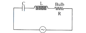
$A$ capacitor,an inductor,and an electric bulb are connected in series to an a.c. supply of variable frequency. As the frequency of the supply is increased gradually,the electric bulb is found to
A
increase in brightness.
B
decrease in brightness.
C
increase,reach a maximum,and then decrease in brightness.
D
show no change in brightness.
Solution
(C) The given circuit is a series $LCR$ circuit where the bulb acts as a resistor $R$.
The current in the circuit is given by $I = \frac{V}{Z} = \frac{V}{\sqrt{R^2 + (\omega L - \frac{1}{\omega C})^2}}$.
At resonance,the angular frequency is $\omega_0 = \frac{1}{\sqrt{LC}}$. At this frequency,the impedance $Z$ is minimum $(Z = R)$,and the current $I$ is maximum $(I = \frac{V}{R})$.
As the frequency increases from a low value,the impedance $Z$ decreases until it reaches the resonance frequency,causing the current $I$ and the brightness of the bulb to increase to a maximum.
As the frequency increases further beyond the resonance frequency,the impedance $Z$ increases again,causing the current $I$ and the brightness of the bulb to decrease.
Therefore,the brightness increases,reaches a maximum at resonance,and then decreases.
0 likes
View Solution109
EasyMCQ
$A$ rejector circuit is the resonant circuit in which
A
$L-C-R$ are connected in parallel.
B
$L-C-R$ are connected in series.
C
$C-R$ are connected in series.
D
$L-R$ are connected in series.
Solution
(A) rejector circuit,also known as a parallel resonant circuit,is a circuit in which an inductor $(L)$ and a capacitor $(C)$ are connected in parallel. At the resonant frequency,the impedance of this parallel combination becomes maximum,which effectively rejects or blocks the current at that specific frequency. Therefore,$L-C-R$ components are connected in parallel to form a rejector circuit.
0 likes
View Solution110
MediumMCQ
An a.c. source is applied to a series $LR$ circuit with $X_L = 3R$ and the power factor is $X_1$. Now,a capacitor with $X_C = R$ is added in series to the $LR$ circuit and the power factor is $X_2$. The ratio $X_1$ to $X_2$ is
A
$1: 2$
B
$2: 1$
C
$1: \sqrt{2}$
D
$\sqrt{2}: 1$
Solution
(C) The power factor of an $LR$ circuit is given by $\cos \phi = \frac{R}{Z} = \frac{R}{\sqrt{R^2 + X_L^2}}$.
Given $X_L = 3R$,the power factor $X_1$ is:
$X_1 = \frac{R}{\sqrt{R^2 + (3R)^2}} = \frac{R}{\sqrt{R^2 + 9R^2}} = \frac{R}{\sqrt{10R^2}} = \frac{1}{\sqrt{10}}$.
When a capacitor with $X_C = R$ is added in series,the circuit becomes an $LCR$ circuit.
The impedance $Z'$ of the $LCR$ circuit is $Z' = \sqrt{R^2 + (X_L - X_C)^2}$.
Given $X_L = 3R$ and $X_C = R$,we have $X_L - X_C = 3R - R = 2R$.
Thus,$Z' = \sqrt{R^2 + (2R)^2} = \sqrt{R^2 + 4R^2} = \sqrt{5R^2} = R\sqrt{5}$.
The new power factor $X_2$ is:
$X_2 = \frac{R}{Z'} = \frac{R}{R\sqrt{5}} = \frac{1}{\sqrt{5}}$.
The ratio $X_1 : X_2$ is:
$\frac{X_1}{X_2} = \frac{1/\sqrt{10}}{1/\sqrt{5}} = \frac{\sqrt{5}}{\sqrt{10}} = \frac{1}{\sqrt{2}}$.
Therefore,the ratio is $1: \sqrt{2}$.
0 likes
View Solution111
EasyMCQ
In an a.c. circuit containing $L, C$ and $R$ in series,the ratio of apparent power to the true power is ($Z$ and $R$ are the impedance and resistance respectively,$\phi$ = phase angle).
A
$\cot \phi$
B
$\cos \phi$
C
$RZ$
D
$\frac{Z}{R}$
Solution
(D) The apparent power in an a.c. circuit is given by $P_{app} = V_{rms} I_{rms} = I_{rms}^2 Z$.
The true power (or average power) in an a.c. circuit is given by $P_{true} = V_{rms} I_{rms} \cos \phi = I_{rms}^2 R$.
The ratio of apparent power to true power is $\frac{P_{app}}{P_{true}} = \frac{I_{rms}^2 Z}{I_{rms}^2 R} = \frac{Z}{R}$.
Since $\cos \phi = \frac{R}{Z}$,we have $\frac{Z}{R} = \frac{1}{\cos \phi} = \sec \phi$.
0 likes
View Solution112
EasyMCQ
$A$ resistor of resistance $30 \Omega$, an inductor of reactance $10 \Omega$, and a capacitor of reactance $10 \Omega$ are connected in series to an $AC$ voltage source $V = 300 \sqrt{2} \sin(\omega t)$. The current in the circuit is . . . . . . (in $\text{ A}$)
A
$10$
B
$30$
C
$20$
D
$100$
Solution
(A) The given $AC$ voltage source is $V = 300 \sqrt{2} \sin(\omega t)$.
The peak voltage is $V_m = 300 \sqrt{2} \text{ V}$.
The $RMS$ voltage is $V_{rms} = \frac{V_m}{\sqrt{2}} = 300 \text{ V}$.
The impedance $Z$ of an $LCR$ series circuit is given by $Z = \sqrt{R^2 + (X_L - X_C)^2}$.
Given $R = 30 \Omega$, $X_L = 10 \Omega$, and $X_C = 10 \Omega$.
$Z = \sqrt{30^2 + (10 - 10)^2} = \sqrt{30^2 + 0^2} = 30 \Omega$.
The $RMS$ current $I_{rms}$ is given by $I_{rms} = \frac{V_{rms}}{Z}$.
$I_{rms} = \frac{300}{30} = 10 \text{ A}$.
0 likes
View Solution113
EasyMCQ
An $L-C-R$ series circuit is connected to an $AC$ source of peak voltage $240 \ V$. The phase difference between voltage and current of this circuit is $45^{\circ}$ and the resistance is $100 \ \Omega$. The $rms$ value of current through the circuit is . . . . . . . (in $A$)
A
$5.25$
B
$3.5$
C
$1.7$
D
$1.2$
Solution
(D) For an $L-C-R$ series circuit,the phase difference $\phi$ is given by $\tan \phi = \frac{|X_C - X_L|}{R}$.
Given $\phi = 45^{\circ}$ and $R = 100 \ \Omega$,we have $\tan 45^{\circ} = 1 = \frac{|X_C - X_L|}{R}$,which implies $|X_C - X_L| = R = 100 \ \Omega$.
The impedance $Z$ of the circuit is $Z = \sqrt{R^2 + (X_C - X_L)^2} = \sqrt{R^2 + R^2} = R\sqrt{2} = 100\sqrt{2} \ \Omega$.
The peak voltage $V_m = 240 \ V$. The $rms$ voltage is $V_{rms} = \frac{V_m}{\sqrt{2}} = \frac{240}{\sqrt{2}} \ V$.
The $rms$ current is $I_{rms} = \frac{V_{rms}}{Z} = \frac{240 / \sqrt{2}}{100\sqrt{2}} = \frac{240}{100 \times 2} = \frac{240}{200} = 1.2 \ A$.
0 likes
View Solution114
MediumMCQ
$A$ series $LCR$ circuit containing an $AC$ source of $100 \ V$ has an inductor and a capacitor of reactances $24 \ \Omega$ and $16 \ \Omega$ respectively. If a resistance of $6 \ \Omega$ is connected in series,then the potential difference across the series combination of inductor and capacitor only is (in $V$)
A
$80$
B
$400$
C
$8$
D
$40$
Solution
(A) Given: $X_L = 24 \ \Omega$,$X_C = 16 \ \Omega$,$R = 6 \ \Omega$,$V = 100 \ V$.
In a series $LCR$ circuit,the impedance $Z$ is given by:
$Z = \sqrt{R^2 + (X_L - X_C)^2}$
$Z = \sqrt{6^2 + (24 - 16)^2} = \sqrt{6^2 + 8^2} = \sqrt{36 + 64} = \sqrt{100} = 10 \ \Omega$.
The current $i$ in the circuit is:
$i = \frac{V}{Z} = \frac{100}{10} = 10 \ A$.
The potential difference across the series combination of the inductor and capacitor is given by:
$V_{LC} = i |X_L - X_C|$
$V_{LC} = 10 \times |24 - 16| = 10 \times 8 = 80 \ V$.
0 likes
View Solution115
MediumMCQ
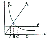
The figure shows the variation of $R$,$X_L$,and $X_C$ with frequency $f$ in a series $L-C-R$ circuit. For what frequency point is the circuit capacitive?
A
$B$
B
$D$
C
$A$
D
$C$
Solution
(C) In a series $L-C-R$ circuit,the circuit is capacitive when the capacitive reactance $X_C$ is greater than the inductive reactance $X_L$ (i.e.,$X_C > X_L$).
From the given graph,the intersection point $B$ represents the resonance frequency where $X_L = X_C$.
For frequencies less than the resonance frequency (i.e.,to the left of point $B$),the curve for $X_C$ lies above the curve for $X_L$,meaning $X_C > X_L$.
Among the given options,point $A$ lies to the left of point $B$,where $X_C > X_L$. Therefore,the circuit is capacitive at point $A$.
0 likes
View Solution116
EasyMCQ
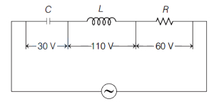
In the given circuit,the peak voltages across $C$,$L$,and $R$ are $30 \,V$,$110 \,V$,and $60 \,V$,respectively. The rms value of the applied voltage is (in $\,V$)
A
$100$
B
$200$
C
$70.7$
D
$141$
Solution
(C) Given,peak voltages are $V_{C}=30 \,V$,$V_{L}=110 \,V$,and $V_{R}=60 \,V$.
The peak voltage $(V_{0})$ across a series $L-C-R$ circuit is given by the formula:
$V_{0} = \sqrt{V_{R}^{2} + (V_{L} - V_{C})^{2}}$
Substituting the given values:
$V_{0} = \sqrt{(60)^{2} + (110 - 30)^{2}}$
$V_{0} = \sqrt{60^{2} + 80^{2}}$
$V_{0} = \sqrt{3600 + 6400} = \sqrt{10000} = 100 \,V$
The rms value of the applied voltage is related to the peak voltage by $V_{\text{rms}} = \frac{V_{0}}{\sqrt{2}}$.
$V_{\text{rms}} = \frac{100}{\sqrt{2}} \approx 70.7 \,V$.
0 likes
View Solution117
EasyMCQ
In a series $LCR$ circuit,the power dissipation occurs through
A
$R$
B
$L$
C
$C$
D
Both $L$ and $C$
Solution
(A) The instantaneous power dissipated in an electrical circuit is given by $P = I^2 R$.
In a series $LCR$ circuit,the inductor $(L)$ and the capacitor $(C)$ are reactive components that store energy in magnetic and electric fields,respectively,but they do not dissipate energy as heat.
The resistance $(R)$ is the only component that dissipates electrical energy into heat.
Therefore,the power dissipation in a series $LCR$ circuit occurs only through the resistance $R$.
0 likes
View Solution118
EasyMCQ
In an $R-L-C$ series circuit, the potential difference across each element is $20 \, V$. If the value of the resistance $R$ is doubled, what will be the potential difference across $R, L$, and $C$ respectively?
A
$20 \, V, 10 \, V, 10 \, V$
B
$20 \, V, 20 \, V, 20 \, V$
C
$20 \, V, 40 \, V, 40 \, V$
D
$10 \, V, 20 \, V, 20 \, V$
Solution
(A) Initially, the potential difference across each element is $V_R = V_L = V_C = 20 \, V$. Since $V_L = V_C$, the circuit is at resonance, meaning the impedance $Z = R$. The source voltage is $V = V_R = 20 \, V$.
When the resistance $R$ is doubled to $2R$, the new impedance becomes $Z' = \sqrt{(2R)^2 + (X_L - X_C)^2}$. Since $X_L = X_C$ at resonance, $Z' = 2R$.
The new current in the circuit is $I' = V / Z' = V / (2R) = I / 2$, where $I$ is the original current.
The new potential difference across the resistor is $V_R' = I' \times (2R) = (I/2) \times (2R) = IR = 20 \, V$.
The new potential difference across the inductor is $V_L' = I' X_L = (I/2) X_L = V_L / 2 = 20 / 2 = 10 \, V$.
The new potential difference across the capacitor is $V_C' = I' X_C = (I/2) X_C = V_C / 2 = 20 / 2 = 10 \, V$.
Thus, the new potential differences are $20 \, V, 10 \, V, 10 \, V$.
0 likes
View Solution119
MediumMCQ
An inductance of $\left(\frac{200}{\pi}\right) \text{mH}$,a capacitance of $\left(\frac{10^{-3}}{\pi}\right) \text{F}$,and a resistance of $10 \, \Omega$ are connected in series with an $AC$ source of $220 \, \text{V}, 50 \, \text{Hz}$. The phase angle of the circuit is:
A
$\frac{\pi}{6}$
B
$\frac{\pi}{4}$
C
$\frac{\pi}{2}$
D
$\frac{\pi}{3}$
Solution
(B) The phase angle $\theta$ between current $I$ and voltage $V$ in an $LCR$ series circuit is given by the formula:
$\tan \theta = \frac{X_L - X_C}{R}$
First,calculate the inductive reactance $X_L$:
$X_L = 2 \pi f L = 2 \pi \times 50 \times \left( \frac{200}{\pi} \times 10^{-3} \right) = 20 \, \Omega$
Next,calculate the capacitive reactance $X_C$:
$X_C = \frac{1}{2 \pi f C} = \frac{1}{2 \pi \times 50 \times (10^{-3} / \pi)} = \frac{1}{0.1} = 10 \, \Omega$
Given resistance $R = 10 \, \Omega$.
Substituting these values into the phase angle formula:
$\tan \theta = \frac{20 - 10}{10} = \frac{10}{10} = 1$
Since $\tan \theta = 1$,we have $\theta = \tan^{-1}(1) = \frac{\pi}{4}$ radians.
Thus,the phase angle of the circuit is $\frac{\pi}{4}$.
0 likes
View Solution120
EasyMCQ
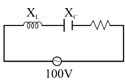
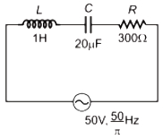
In the series $L-C-R$ circuit shown,the impedance is (in $Omega$)
A
$200$
B
$100$
C
$300$
D
$500$
Solution
(D) Given: Inductance $L = 1 \text{ H}$,Capacitance $C = 20 \mu\text{F} = 20 \times 10^{-6} \text{ F}$,Resistance $R = 300 \Omega$,Frequency $f = \frac{50}{\pi} \text{ Hz}$.
First,calculate the inductive reactance $X_{L}$:
$X_{L} = 2 \pi f L = 2 \pi \left(\frac{50}{\pi}\right) \times 1 = 100 \Omega$.
Next,calculate the capacitive reactance $X_{C}$:
$X_{C} = \frac{1}{2 \pi f C} = \frac{1}{2 \pi \left(\frac{50}{\pi}\right) \times 20 \times 10^{-6}} = \frac{1}{100 \times 20 \times 10^{-6}} = \frac{1}{2 \times 10^{-3}} = 500 \Omega$.
The impedance $Z$ of a series $L-C-R$ circuit is given by:
$Z = \sqrt{R^{2} + (X_{C} - X_{L})^{2}}$.
Substituting the values:
$Z = \sqrt{(300)^{2} + (500 - 100)^{2}} = \sqrt{300^{2} + 400^{2}} = \sqrt{90000 + 160000} = \sqrt{250000} = 500 \Omega$.
0 likes
View Solution121
EasyMCQ
$A$ capacitor and an inductance coil are connected in separate $AC$ circuits with a bulb glowing in both the circuits. The bulb glows more brightly when
A
an iron rod is introduced into the inductance coil
B
the number of turns in the inductance coil is increased
C
separation between the plates of the capacitor is increased
D
a dielectric is introduced into the gap between the plates of the capacitor
Solution
(D) The current in an $AC$ circuit containing a capacitor is given by $i = \frac{V}{\sqrt{R^2 + X_C^2}}$,where $X_C = \frac{1}{\omega C}$ is the capacitive reactance.
When a dielectric is introduced into the gap between the plates of the capacitor,the capacitance $C$ increases $(C = K C_0)$.
As $C$ increases,the capacitive reactance $X_C = \frac{1}{\omega C}$ decreases.
Since the impedance $Z = \sqrt{R^2 + X_C^2}$ decreases,the current $i$ in the circuit increases.
Consequently,the brightness of the bulb,which depends on the power dissipated $(P = i^2 R)$,increases.
0 likes
View Solution122
DifficultMCQ
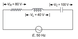
The value of the alternating emf in the given series $LCR$ circuit is: (in $V$)
A
$220$
B
$140$
C
$100$
D
$20$
Solution
(C) In a series $LCR$ circuit,the total alternating emf $(V)$ is given by the phasor sum of the individual voltages across the resistor $(V_R)$,inductor $(V_L)$,and capacitor $(V_C)$.
The formula is:
$V = \sqrt{V_R^2 + (V_L - V_C)^2}$
Given values:
$V_R = 80 \ V$
$V_L = 40 \ V$
$V_C = 100 \ V$
Substituting these values into the formula:
$V = \sqrt{(80)^2 + (40 - 100)^2}$
$V = \sqrt{6400 + (-60)^2}$
$V = \sqrt{6400 + 3600}$
$V = \sqrt{10000}$
$V = 100 \ V$
Therefore,the value of the alternating emf is $100 \ V$.
0 likes
View Solution123
EasyMCQ
$A$ resistor of resistance $40 \Omega$,a capacitor of capacitive reactance $20 \Omega$,and an inductor of inductive reactance $50 \Omega$ are connected in series to an $ac$ source of $100 \ V$. The current through the circuit is (in $A$)
A
$0.5$
B
$1$
C
$1.5$
D
$2$
Solution
(D) The impedance $Z$ of an $LCR$ series circuit is given by $Z = \sqrt{R^2 + (X_L - X_C)^2}$.
Given: $R = 40 \ \Omega$,$X_C = 20 \ \Omega$,$X_L = 50 \ \Omega$,and $V = 100 \ V$.
Substituting the values:
$Z = \sqrt{40^2 + (50 - 20)^2}$
$Z = \sqrt{1600 + 30^2} = \sqrt{1600 + 900} = \sqrt{2500} = 50 \ \Omega$.
The current $i$ in the circuit is given by $i = \frac{V}{Z}$.
$i = \frac{100 \ V}{50 \ \Omega} = 2 \ A$.
0 likes
View Solution124
EasyMCQ
In an $L-C-R$ circuit,the capacitance is changed from $C$ to $4 C$. For the same resonant frequency,the inductance should be changed from $L$ to
A
$2 L$
B
$\frac{L}{2}$
C
$\frac{L}{4}$
D
$4 L$
Solution
(C) In an $L-C-R$ circuit,the resonant frequency $f_0$ is given by the formula:
$f_0 = \frac{1}{2 \pi \sqrt{L C}}$
For the resonant frequency to remain the same,the product $LC$ must remain constant.
Let the new inductance be $L^{\prime}$ and the new capacitance be $C^{\prime} = 4C$.
Since $f_0 = f_0^{\prime}$,we have:
$L C = L^{\prime} C^{\prime}$
Substituting $C^{\prime} = 4C$ into the equation:
$L C = L^{\prime} (4 C)$
Dividing both sides by $4C$:
$L^{\prime} = \frac{L}{4}$
Therefore,the inductance should be changed from $L$ to $\frac{L}{4}$.
0 likes
View Solution125
EasyMCQ
An $R-L-C$ circuit consists of a $150 \Omega$ resistor,$20 \mu F$ capacitor,and a $500 mH$ inductor connected in series with a $100 V$ $AC$ supply. The angular frequency of the supply voltage is $400 rad s^{-1}$. The phase angle between the current and the applied voltage is
A
$\tan^{-1}(0.8)$
B
$\tan^{-1}(0.25)$
C
$\tan^{-1}(0.6)$
D
$\tan^{-1}(0.5)$
Solution
(D) In an $R-L-C$ series circuit,the given values are:
$R = 150 \Omega$
$C = 20 \mu F = 20 \times 10^{-6} F = 2 \times 10^{-5} F$
$L = 500 mH = 0.5 H$
$\omega = 400 rad s^{-1}$
First,calculate the inductive reactance $X_L$:
$X_L = \omega L = 400 \times 0.5 = 200 \Omega$
Next,calculate the capacitive reactance $X_C$:
$X_C = \frac{1}{\omega C} = \frac{1}{400 \times 2 \times 10^{-5}} = \frac{1}{800 \times 10^{-5}} = \frac{10^5}{800} = \frac{1000}{8} = 125 \Omega$
The phase angle $\phi$ is given by the formula:
$\tan \phi = \frac{X_L - X_C}{R}$
Substituting the values:
$\tan \phi = \frac{200 - 125}{150} = \frac{75}{150} = 0.5$
Therefore,the phase angle is $\phi = \tan^{-1}(0.5)$.
0 likes
View Solution126
MediumMCQ
In an $LCR$ series circuit, if the potential differences across the inductor, capacitor, and resistor are $60 \,V$, $30 \,V$, and $40 \,V$ respectively, then the $AC$ voltage applied to the circuit is: (in $\,V$)
A
$50$
B
$70$
C
$130$
D
$60$
Solution
(A) In an $LCR$ series circuit, the applied voltage $V$ is given by the phasor sum of the potential differences across the components.
The formula for the applied voltage is $V = \sqrt{V_R^2 + (V_L - V_C)^2}$.
Given values are:
$V_R = 40 \,V$
$V_L = 60 \,V$
$V_C = 30 \,V$
Substituting these values into the formula:
$V = \sqrt{40^2 + (60 - 30)^2}$
$V = \sqrt{40^2 + 30^2}$
$V = \sqrt{1600 + 900}$
$V = \sqrt{2500}$
$V = 50 \,V$.
Therefore, the applied $AC$ voltage is $50 \,V$.
0 likes
View Solution127
EasyMCQ
In a series $L-C-R$ circuit,the inductive reactance is twice the resistance and the capacitive reactance is $1/3$ rd of the inductive reactance. The power factor of the circuit is
A
$1.5$
B
$1.15$
C
$0.6$
D
$0.5$
Solution
(C) In an $L-C-R$ circuit,we are given:
$X_L = 2R$ and $X_C = \frac{X_L}{3}$.
Substituting $X_L = 2R$ into the expression for $X_C$,we get $X_C = \frac{2R}{3}$.
The impedance $Z$ of the $L-C-R$ circuit is given by the formula:
$Z = \sqrt{R^2 + (X_L - X_C)^2}$.
Substituting the values of $X_L$ and $X_C$:
$Z = \sqrt{R^2 + (2R - \frac{2R}{3})^2} = \sqrt{R^2 + (\frac{4R}{3})^2} = \sqrt{R^2 + \frac{16R^2}{9}} = \sqrt{\frac{25R^2}{9}} = \frac{5R}{3}$.
The power factor is defined as $\cos \phi = \frac{R}{Z}$.
Substituting the value of $Z$:
$\cos \phi = \frac{R}{5R/3} = \frac{3}{5} = 0.6$.
0 likes
View Solution128
EasyMCQ
An inductor and a resistor are connected in series to an $AC$ source. If the power factor of the circuit is $0.5$, the ratio of the resistance of the resistor and the reactance of the inductor is:
A
$1:1$
B
$1: \sqrt{2}$
C
$1: \sqrt{3}$
D
$1: 2$
Solution
(C) The power factor $(\cos \phi)$ of an $LR$ series circuit is given by $\cos \phi = \frac{R}{Z}$, where $R$ is the resistance and $Z$ is the impedance.
Given, $\cos \phi = 0.5 = \frac{1}{2}$.
We know that $Z = \sqrt{R^2 + X_L^2}$, where $X_L$ is the inductive reactance.
So, $\frac{R}{\sqrt{R^2 + X_L^2}} = \frac{1}{2}$.
Squaring both sides, we get $\frac{R^2}{R^2 + X_L^2} = \frac{1}{4}$.
$4R^2 = R^2 + X_L^2$.
$3R^2 = X_L^2$.
Taking the square root, $\sqrt{3}R = X_L$.
Therefore, the ratio of resistance to reactance is $\frac{R}{X_L} = \frac{1}{\sqrt{3}}$.
0 likes
View Solution129
EasyMCQ
In a series $LCR$ circuit,if the current leads the source voltage,then
A
$X_C > X_L$
B
$X_L > X_C$
C
$X_L = X_C \neq 0$
D
$X_L = X_C = 0$
Solution
(A) The phase difference $\phi$ between the current and the voltage in a series $LCR$ circuit is given by the relation:
$\tan \phi = \frac{X_L - X_C}{R}$
In a series $LCR$ circuit,the current leads the source voltage when the circuit is capacitive in nature.
This happens when the capacitive reactance $X_C$ is greater than the inductive reactance $X_L$,i.e.,$X_C > X_L$.
In this condition,the phase angle $\phi$ becomes negative,indicating that the current leads the voltage.
0 likes
View Solution130
MediumMCQ
Which of the following components of an $L-C-R$ circuit,with an $AC$ supply,dissipates energy?
A
Only $L$
B
Only $R$
C
Only $C$
D
$L$ and $C$
Solution
(B) In an $AC$ circuit,the average power dissipated is given by the formula:
$P = V_{rms} I_{rms} \cos \phi$
where $\phi$ is the phase difference between voltage and current.
For an ideal inductor $(L)$ and an ideal capacitor $(C)$,the phase difference between voltage and current is $90^{\circ}$.
Therefore,the power dissipated by $L$ or $C$ is:
$P_{L \text{ or } C} = V I \cos 90^{\circ} = 0$ (since $\cos 90^{\circ} = 0$).
For a resistor $(R)$,the voltage and current are in phase,so the phase difference $\phi = 0^{\circ}$.
Thus,the power dissipated by the resistor is $P_R = V I \cos 0^{\circ} = V I$.
Hence,only the resistor $(R)$ dissipates energy in an $L-C-R$ circuit.
0 likes
View Solution131
EasyMCQ
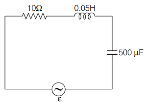
An alternating voltage $\varepsilon = 30 \sin 200 t$ (in volts) is applied to the circuit shown below. The amplitude of the current through the circuit is (in $\text{ A}$)
A
$3$
B
$2$
C
$1$
D
$0.5$
Solution
(A) Given,the applied electromotive force (emf) is $E = 30 \sin 200 t$.
Comparing this with $E = E_{\max} \sin \omega t$,we get $E_{\max} = 30 \text{ V}$ and $\omega = 200 \text{ rad s}^{-1}$.
From the circuit diagram,we have resistance $R = 10 \Omega$,inductance $L = 0.05 \text{ H}$,and capacitance $C = 500 \mu\text{F} = 500 \times 10^{-6} \text{ F}$.
First,calculate the inductive reactance: $X_L = L \omega = 0.05 \times 200 = 10 \Omega$.
Next,calculate the capacitive reactance: $X_C = \frac{1}{C \omega} = \frac{1}{500 \times 10^{-6} \times 200} = \frac{1}{0.1} = 10 \Omega$.
Since $X_L = X_C$,the circuit is in a state of electrical resonance.
In resonance,the impedance of the circuit is $Z = R = 10 \Omega$.
The amplitude of the current is given by $I_{\max} = \frac{E_{\max}}{Z} = \frac{30}{10} = 3 \text{ A}$.
0 likes
View Solution132
EasyMCQ
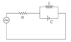
The $L-C-R$ circuit shown below is driven by an ideal $AC$ voltage source. At frequency $f=\frac{1}{2 \pi \sqrt{L C}}$,choose the correct statement.
A
The current through $R$ is zero.
B
The current through $R$ is infinite.
C
The current through $R$ depends on the value of $L$ and $C$.
D
The current through $R$ depends only on the value of $R$ and not $L$ and $C$.
Solution
(A) The circuit consists of a resistor $R$ in series with a parallel combination of an inductor $L$ and a capacitor $C$.
At the given frequency $f = \frac{1}{2 \pi \sqrt{L C}}$,the angular frequency is $\omega = 2 \pi f = \frac{1}{\sqrt{L C}}$.
This is the resonant frequency of the $L-C$ parallel circuit.
At this frequency,the inductive reactance $X_L = \omega L$ and capacitive reactance $X_C = \frac{1}{\omega C}$ are equal,i.e.,$X_L = X_C$.
For a parallel $L-C$ circuit,the equivalent impedance $Z_{LC}$ is given by $\frac{1}{Z_{LC}} = \sqrt{(\frac{1}{X_L})^2 + (\frac{1}{X_C} - \frac{1}{X_L})^2}$ is not correct here; rather,the admittance $Y = \sqrt{(\frac{1}{R_{LC}})^2 + (\frac{1}{X_L} - \frac{1}{X_C})^2}$. Since $X_L = X_C$,the net reactance of the parallel $L-C$ combination becomes infinite $(Z_{LC} \to \infty)$.
Therefore,the parallel $L-C$ combination acts as an open circuit.
Consequently,the current through the entire circuit,including the resistor $R$,becomes zero.
0 likes
View Solution133
DifficultMCQ
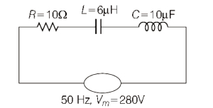
An oscillating circuit consists of a capacitor with capacitance $C = 10 \, \mu F$, a coil with inductance $L = 6.0 \, \mu H$, and active resistance $R = 10 \, \Omega$. The mean power that should be fed to the circuit to maintain undamped harmonic oscillations with an external driving source of frequency $f = 50 \, Hz$ and peak voltage $V_m = 280 \, V$ is:
A
$3.8 \, W$
B
$48 \, W$
C
$3 \, mW$
D
$48 \, mW$
Solution
(A) Given: $R = 10 \, \Omega$, $L = 6.0 \, \mu H = 6.0 \times 10^{-6} \, H$, $C = 10 \, \mu F = 10 \times 10^{-6} \, F$, $f = 50 \, Hz$, $V_m = 280 \, V$.
The angular frequency is $\omega = 2 \pi f = 2 \times 3.14 \times 50 = 314 \, rad/s$.
Capacitive reactance: $X_C = \frac{1}{\omega C} = \frac{1}{314 \times 10 \times 10^{-6}} = \frac{1}{3.14 \times 10^{-3}} \approx 318.47 \, \Omega$.
Inductive reactance: $X_L = \omega L = 314 \times 6.0 \times 10^{-6} = 1.884 \times 10^{-3} \, \Omega$.
Impedance of the circuit: $Z = \sqrt{R^2 + (X_C - X_L)^2} = \sqrt{10^2 + (318.47 - 0.001884)^2} \approx \sqrt{100 + (318.47)^2} \approx 318.63 \, \Omega$.
$RMS$ voltage: $V_{rms} = \frac{V_m}{\sqrt{2}} = \frac{280}{1.414} \approx 198 \, V$.
$RMS$ current: $I_{rms} = \frac{V_{rms}}{Z} = \frac{198}{318.63} \approx 0.621 \, A$.
Average power dissipated as heat in the resistor: $P = I_{rms}^2 R = (0.621)^2 \times 10 = 0.3856 \times 10 \approx 3.86 \, W$.
Rounding to the nearest given option, the power is $3.8 \, W$.
0 likes
View Solution134
MediumMCQ
In a circuit,$L$,$C$,and $R$ are connected in series with an alternating voltage source of frequency $f$. When the current in the circuit leads the voltage by $45^{\circ}$,the value of $C$ is
A
$\frac{1}{2 \pi f(2 \pi f L+R)}$
B
$\frac{1}{2 \pi f(2 \pi f R+L)}$
C
$\frac{2}{2 \pi f(R+L)}$
D
$\frac{2}{2 \pi f\left(R+\frac{1}{L}\right)}$
Solution
(A) In an $LCR$ series circuit,the phase difference $\phi$ between voltage and current is given by $\tan \phi = \frac{X_C - X_L}{R}$.
Since the current leads the voltage,the phase angle is $\phi = -45^{\circ}$.
Therefore,$\tan(-45^{\circ}) = \frac{X_C - X_L}{R} = -1$.
This implies $X_L - X_C = R$,or $X_C - X_L = -R$.
However,the standard convention for current leading is $\tan \phi = \frac{X_L - X_C}{R}$ where $\phi$ is the phase of voltage relative to current. If current leads,$\phi = -45^{\circ}$,so $\tan(-45^{\circ}) = -1 = \frac{X_L - X_C}{R}$,which gives $X_C - X_L = R$.
Substituting $X_C = \frac{1}{2 \pi f C}$ and $X_L = 2 \pi f L$:
$\frac{1}{2 \pi f C} - 2 \pi f L = R$
$\frac{1}{2 \pi f C} = R + 2 \pi f L$
$C = \frac{1}{2 \pi f (R + 2 \pi f L)}$.
0 likes
View Solution135
MediumMCQ
$A$ capacitance of $\left(\frac{10^{-3}}{2 \pi}\right) F$,an inductance of $\left(\frac{100}{\pi}\right) mH$,and a resistance of $10 \Omega$ are connected in series with an $AC$ voltage source of $220 V, 50 Hz$. The phase angle of the circuit is (in $^{\circ}$)
A
$60$
B
$30$
C
$45$
D
$90$
Solution
(C) Given: Capacitance $C = \frac{10^{-3}}{2 \pi} F$,Inductance $L = \frac{100}{\pi} mH = \frac{100}{\pi} \times 10^{-3} H$,Resistance $R = 10 \Omega$,and Frequency $f = 50 Hz$.
First,calculate the inductive reactance $X_L = \omega L = 2 \pi f L = 2 \pi \times 50 \times \frac{100}{\pi} \times 10^{-3} = 10 \Omega$.
Next,calculate the capacitive reactance $X_C = \frac{1}{\omega C} = \frac{1}{2 \pi f C} = \frac{1}{2 \pi \times 50 \times \frac{10^{-3}}{2 \pi}} = \frac{1}{50 \times 10^{-3}} = \frac{1000}{50} = 20 \Omega$.
The phase angle $\phi$ is given by $\tan \phi = \frac{X_C - X_L}{R}$.
Substituting the values: $\tan \phi = \frac{20 - 10}{10} = \frac{10}{10} = 1$.
Therefore,$\phi = \tan^{-1}(1) = 45^{\circ}$.
0 likes
View Solution136
MediumMCQ
$A$ coil is connected to an $AC$ source with peak emf, $8 \, V$ and frequency $\frac{30}{\pi} \, Hz$. The coil has a resistance of $8 \, \Omega$. If the average power dissipated by the coil is $0.4 \, W$, then the inductance of the coil is (in $, H$)
A
$0.8$
B
$2.0$
C
$1.4$
D
$0.4$
Solution
(D) Given: Peak emf, $V_0 = 8 \, V$, Frequency $f = \frac{30}{\pi} \, Hz$, Resistance $R = 8 \, \Omega$, Average power $P_{avg} = 0.4 \, W$.
$V_{rms} = \frac{V_0}{\sqrt{2}} = \frac{8}{\sqrt{2}} \, V$.
Average power is given by $P_{avg} = V_{rms} I_{rms} \cos \phi = V_{rms} \left(\frac{V_{rms}}{Z}\right) \left(\frac{R}{Z}\right) = \frac{V_{rms}^2 R}{Z^2}$.
Substituting the values: $0.4 = \frac{(8/\sqrt{2})^2 \times 8}{Z^2} = \frac{32 \times 8}{Z^2} = \frac{256}{Z^2}$.
$Z^2 = \frac{256}{0.4} = 640 \, \Omega^2$.
Since $Z^2 = R^2 + X_L^2$, we have $640 = 8^2 + X_L^2 = 64 + X_L^2$.
$X_L^2 = 640 - 64 = 576$, so $X_L = 24 \, \Omega$.
Using $X_L = 2 \pi f L$, we get $24 = 2 \pi (\frac{30}{\pi}) L = 60 L$.
$L = \frac{24}{60} = 0.4 \, H$.
0 likes
View Solution137
MediumMCQ
$A$ sinusoidal voltage with a frequency of $50 \ Hz$ is applied to a series $LCR$ circuit with a resistance of $5 \ \Omega$,inductance of $20 \ mH$ and a capacitance of $500 \ \mu F$. The magnitude of impedance of the circuit is close to (in $Omega$)
A
$19.2$
B
$14.4$
C
$9.6$
D
$5$
Solution
(D) The impedance $Z$ for a series $LCR$ circuit is given by the formula: $Z = \sqrt{R^2 + (X_L - X_C)^2}$.
Here,$R = 5 \ \Omega$,$L = 20 \ mH = 20 \times 10^{-3} \ H$,and $C = 500 \ \mu F = 500 \times 10^{-6} \ F$.
The angular frequency is $\omega = 2 \pi f = 2 \pi \times 50 = 100 \pi \ rad/s$.
Inductive reactance $X_L = \omega L = 100 \pi \times 20 \times 10^{-3} = 2 \pi \approx 6.28 \ \Omega$.
Capacitive reactance $X_C = \frac{1}{\omega C} = \frac{1}{100 \pi \times 500 \times 10^{-6}} = \frac{1}{0.05 \pi} = \frac{20}{\pi} \approx 6.37 \ \Omega$.
Now,$Z = \sqrt{5^2 + (6.28 - 6.37)^2} = \sqrt{25 + (-0.09)^2} = \sqrt{25 + 0.0081} = \sqrt{25.0081} \approx 5 \ \Omega$.
0 likes
View Solution138
DifficultMCQ
An inductor of $10 \text{ mH}$,capacitor of $0.1 \text{ } \mu\text{F}$ and a resistor of $100 \text{ } \Omega$ are connected in series across an $a.c.$ power supply of $220 \text{ V}$,$70 \text{ Hz}$. The power factor of the given circuit is $0.5$. The difference between the inductive reactance and capacitive reactance is $\sqrt{3}\alpha \text{ } \Omega$. The value of $\alpha$ is . . . . . . .
A
$50$
B
$100$
C
$150$
D
$200$
Solution
(B) The power factor is given by $\cos \phi = \frac{R}{Z} = 0.5$.
Since $R = 100 \text{ } \Omega$,we have $Z = \frac{R}{0.5} = \frac{100}{0.5} = 200 \text{ } \Omega$.
The impedance of an $LCR$ series circuit is given by $Z = \sqrt{R^2 + (X_L - X_C)^2}$.
Squaring both sides,$Z^2 = R^2 + (X_L - X_C)^2$.
Substituting the values,$200^2 = 100^2 + (X_L - X_C)^2$.
$40000 = 10000 + (X_L - X_C)^2$.
$(X_L - X_C)^2 = 30000$.
$|X_L - X_C| = \sqrt{30000} = 100\sqrt{3} \text{ } \Omega$.
Given that the difference is $\sqrt{3}\alpha \text{ } \Omega$,we equate $\sqrt{3}\alpha = 100\sqrt{3}$.
Therefore,$\alpha = 100$.
0 likes
View SolutionAlternating Current — Inductance, Capacitance and Resistance in Series and Parallel · Frequently Asked Questions
1Are these Alternating Current questions useful for JEE and NEET?
Yes. All questions in this section are mapped to JEE Main and NEET exam patterns. Previous year questions from JEE Main, NEET, GUJCET and state-level exams are included with full solutions.
2Can I switch to Hindi or Gujarati for these questions?
Yes. Use the language tabs in the hero section or the sidebar to view the same questions and solutions in English, Hindi or Gujarati.
3How do I generate a question paper from this subtopic?
Use the Vedclass Exam Paper Generator — select the chapter and subtopic, set difficulty, and generate Sets A, B, C, D automatically. First 3 chapters of every subject are free.
Vedclass Products
For Students
Vedclass Test Series
Mock tests in real JEE/NEET style with performance analysis. 5-day free trial.
Start Free TrialFor Teachers
Exam Paper Generator
Generate Set A/B/C/D papers from this chapter in 2 minutes. 3 chapters free.
Try FreeFor Institutes
Online Exam Module
Live online exams with unlimited students, 360° analytics & white-label branding.
See DemoFor Teachers & Institutes
Generate a Alternating Current Exam Paper in 2 Minutes
Select subtopic & difficulty — Sets A, B, C, D auto-generated with No Repeat logic.
First 3 chapters of every subject are free — no payment required.