
A English
Zener Diode Questions in English
Class 12 Physics · Semiconductor Electronics · Zener Diode
108+
Questions
English
Language
100%
With Solutions
Showing 50 of 108 questions in English
51
MediumMCQ
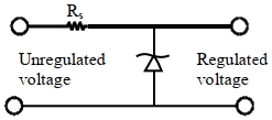
Consider the following statements $(A)$ and $(B)$ and identify the correct answer.
$(A)$ $A$ Zener diode is connected in reverse bias when used as a voltage regulator.
$(B)$ The potential barrier of a $p-n$ junction typically lies between $0.1 \, V$ to $0.3 \, V$.
$(A)$ $A$ Zener diode is connected in reverse bias when used as a voltage regulator.
$(B)$ The potential barrier of a $p-n$ junction typically lies between $0.1 \, V$ to $0.3 \, V$.
A
$(A)$ and $(B)$ both are correct.
B
$(A)$ and $(B)$ both are incorrect.
C
$(A)$ is correct and $(B)$ is incorrect.
D
$(A)$ is incorrect but $(B)$ is correct.
Solution
(C) Statement $(A)$ is correct: $A$ Zener diode is specifically designed to operate in the reverse breakdown region,making it an effective voltage regulator.
Statement $(B)$ is incorrect: The potential barrier for a Germanium $(Ge)$ $p-n$ junction is approximately $0.3 \, V$,while for a Silicon $(Si)$ $p-n$ junction,it is approximately $0.7 \, V$. Therefore,the range $0.1 \, V$ to $0.3 \, V$ is not representative of all common $p-n$ junctions,as it excludes the widely used Silicon diodes.
Statement $(B)$ is incorrect: The potential barrier for a Germanium $(Ge)$ $p-n$ junction is approximately $0.3 \, V$,while for a Silicon $(Si)$ $p-n$ junction,it is approximately $0.7 \, V$. Therefore,the range $0.1 \, V$ to $0.3 \, V$ is not representative of all common $p-n$ junctions,as it excludes the widely used Silicon diodes.
0 likes
View Solution52
MediumMCQ
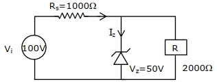
For the circuit shown below,calculate the value of ${I}_{{z}}$ : (In ${mA}$)
A
$0.15$
B
$0.05$
C
$0.1$
D
$25$
Solution
(D) The total voltage across the series resistor ${R}_{s} = 1000 \, \Omega$ is given by $V_{R} = V_{i} - V_{z} = 100 \, V - 50 \, V = 50 \, V$.
The total current flowing through the series resistor is $I = \frac{V_{R}}{R_{s}} = \frac{50 \, V}{1000 \, \Omega} = 0.05 \, A = 50 \, mA$.
The current flowing through the load resistor $R = 2000 \, \Omega$ is $I_{L} = \frac{V_{z}}{R} = \frac{50 \, V}{2000 \, \Omega} = 0.025 \, A = 25 \, mA$.
Using Kirchhoff's Current Law at the junction,the Zener current $I_{z}$ is $I_{z} = I - I_{L} = 50 \, mA - 25 \, mA = 25 \, mA$.
0 likes
View Solution53
MediumMCQ
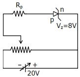
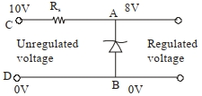
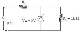
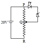
$A$ Zener diode having a Zener voltage of $8\, V$ and a power dissipation rating of $0.5\, W$ is connected across a potential divider circuit as shown in the diagram. The value of the protective resistance $R_p$ is $....\, \Omega$.
A
$123$
B
$456$
C
$192$
D
$219$
Solution
(C) The power dissipation rating of the Zener diode is given by $P = V_z \cdot I_z$,where $V_z = 8\, V$ and $P = 0.5\, W$.
Calculating the maximum current $I_z$ through the Zener diode:
$I_z = \frac{P}{V_z} = \frac{0.5}{8} = \frac{1}{16}\, A$.
In the circuit,the total voltage $E = 20\, V$ is divided between the protective resistance $R_p$ and the Zener diode.
The voltage drop across the protective resistance $R_p$ is $V_{R_p} = E - V_z = 20\, V - 8\, V = 12\, V$.
Using Ohm's law for the protective resistance $R_p = \frac{V_{R_p}}{I_z}$:
$R_p = \frac{12}{1/16} = 12 \times 16 = 192\, \Omega$.
0 likes
View Solution54
DifficultMCQ
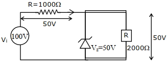
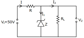
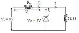
In the given circuit diagram,a $5 \,V$ Zener diode along with a series resistance $R$ is connected across a $50 \,V$ power supply. If the maximum Zener current is $90 \,mA$,the minimum value of the resistance $R$ required will be $..... \,\Omega$.
A
$100$
B
$1000$
C
$500$
D
$50$
Solution
(C) The Zener diode is connected in parallel with the load resistance $R_L$. The voltage across the Zener diode is constant at $V_Z = 5 \,V$.
The voltage drop across the series resistor $R$ is $V_R = V_i - V_Z = 50 \,V - 5 \,V = 45 \,V$.
The total current $I$ flowing through the series resistor $R$ is the sum of the Zener current $I_Z$ and the load current $I_L$,so $I = I_Z + I_L$.
To find the minimum value of $R$,we use the relation $R = \frac{V_R}{I}$. Since $V_R$ is constant,$R$ is minimum when the total current $I$ is maximum.
The current $I$ is maximum when the Zener current $I_Z$ is at its maximum value $(90 \,mA)$ and the load current $I_L$ is zero (which occurs when the load is disconnected or $R_L \rightarrow \infty$).
Thus,$I_{max} = I_{Z,max} + 0 = 90 \,mA = 90 \times 10^{-3} \,A$.
Therefore,$R_{min} = \frac{45 \,V}{90 \times 10^{-3} \,A} = \frac{45000}{90} \,\Omega = 500 \,\Omega$.
0 likes
View Solution55
EasyMCQ
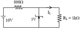
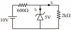
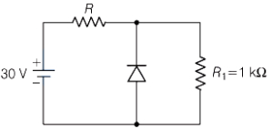
In the given circuit,the value of current $I_{L}$ will be in $mA$. (When $R_{L} = 1 \, k\Omega$)
A
$5$
B
$55$
C
$7$
D
$1$
Solution
(A) The Zener diode is connected in parallel with the load resistor $R_{L}$.
Since the Zener diode is in the breakdown region,the voltage across the load resistor $R_{L}$ is equal to the Zener breakdown voltage,which is $V_{Z} = 5 \, V$.
The load current $I_{L}$ is given by Ohm's law:
$I_{L} = \frac{V_{Z}}{R_{L}}$
Given $V_{Z} = 5 \, V$ and $R_{L} = 1 \, k\Omega = 1000 \, \Omega$.
$I_{L} = \frac{5 \, V}{1000 \, \Omega} = 0.005 \, A = 5 \, mA$.
0 likes
View Solution56
DifficultMCQ
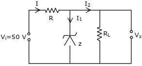
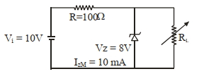
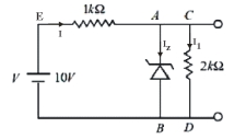
$A$ Zener diode of breakdown voltage $V_{Z} = 8\,V$ and maximum Zener current $I_{ZM} = 10\,mA$ is subjected to an input voltage $V_{i} = 10\,V$ with a series resistance $R = 100\,\Omega$. In the given circuit,$R_{L}$ represents the variable load resistance. The ratio of the maximum and minimum value of $R_{L}$ is
A
$1$
B
$2$
C
$3$
D
$4$
Solution
(B) The total current $I$ flowing through the series resistor $R$ is given by:
$I = \frac{V_{i} - V_{Z}}{R} = \frac{10\,V - 8\,V}{100\,\Omega} = \frac{2\,V}{100\,\Omega} = 20\,mA$.
For the Zener diode to operate in the breakdown region,the load current $I_{L}$ must satisfy $I = I_{Z} + I_{L}$,where $0 \le I_{Z} \le I_{ZM}$.
$1$. To find $R_{L, \max}$,we need the minimum load current $I_{L, \min}$. This occurs when the Zener current is at its maximum $(I_{Z} = I_{ZM} = 10\,mA)$.
$I_{L, \min} = I - I_{ZM} = 20\,mA - 10\,mA = 10\,mA$.
$R_{L, \max} = \frac{V_{Z}}{I_{L, \min}} = \frac{8\,V}{10\,mA} = 800\,\Omega$.
$2$. To find $R_{L, \min}$,we need the maximum load current $I_{L, \max}$. This occurs when the Zener current is at its minimum $(I_{Z} = 0)$.
$I_{L, \max} = I = 20\,mA$.
$R_{L, \min} = \frac{V_{Z}}{I_{L, \max}} = \frac{8\,V}{20\,mA} = 400\,\Omega$.
The ratio of the maximum and minimum value of $R_{L}$ is:
$\frac{R_{L, \max}}{R_{L, \min}} = \frac{800\,\Omega}{400\,\Omega} = 2$.
1 likes
View Solution57
MediumMCQ
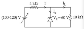
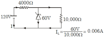
In the circuit shown below,the maximum Zener diode current will be $..... \text{mA}$.
A
$9$
B
$90$
C
$95$
D
$45$
Solution
(A) The Zener diode current $I_Z$ is given by $I_Z = I - I_L$,where $I$ is the total current from the source and $I_L$ is the load current.
To maximize $I_Z$,we must maximize the total current $I$. Since $I = \frac{V_{in} - V_Z}{R}$,$I$ is maximum when $V_{in}$ is maximum $(V_{in} = 120 \text{ V})$.
$I_{max} = \frac{120 \text{ V} - 60 \text{ V}}{4000 \ \Omega} = \frac{60 \text{ V}}{4000 \ \Omega} = 0.015 \text{ A} = 15 \text{ mA}$.
The load current $I_L$ is constant because the voltage across the load resistor is fixed at $V_Z = 60 \text{ V}$.
$I_L = \frac{V_Z}{R_L} = \frac{60 \text{ V}}{10000 \ \Omega} = 0.006 \text{ A} = 6 \text{ mA}$.
Therefore,the maximum Zener diode current is $I_{Z,max} = I_{max} - I_L = 15 \text{ mA} - 6 \text{ mA} = 9 \text{ mA}$.
0 likes
View Solution58
MediumMCQ
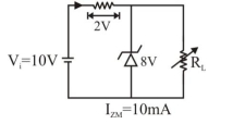
An $8\,V$ Zener diode along with a series resistance $R$ is connected across a $20\,V$ supply (as shown in the figure). If the maximum Zener current is $25\,mA$,then the minimum value of $R$ will be $\Omega$.
A
$480$
B
$441$
C
$420$
D
$460$
Solution
(A) The voltage across the series resistor $R$ is given by the difference between the supply voltage $V_{S}$ and the Zener breakdown voltage $V_{Z}$.
$V_{R} = V_{S} - V_{Z} = 20\,V - 8\,V = 12\,V$.
To find the minimum value of the series resistance $R$,we must use the maximum Zener current $I_{Z,max} = 25\,mA = 25 \times 10^{-3}\,A$.
Using Ohm's law,$V_{R} = I_{Z,max} \times R$.
$12\,V = (25 \times 10^{-3}\,A) \times R$.
$R = \frac{12}{25 \times 10^{-3}}\,\Omega = \frac{12000}{25}\,\Omega = 480\,\Omega$.
0 likes
View Solution59
MediumMCQ
$A$ certain $p-n$ junction,having a depletion region of width $20 \,\mu m$,was found to have a breakdown voltage of $100 \,V$. If the width of the depletion region is reduced to $1 \,\mu m$ during its production,then it can be used as a zener diode for voltage regulation of .......... $V$.
A
$5$
B
$10$
C
$7.5$
D
$2000$
Solution
(A) The breakdown electric field $E$ in a $p-n$ junction is a characteristic property of the material and is independent of the depletion width.
Given,the breakdown voltage $V_1 = 100 \,V$ for a depletion width $d_1 = 20 \,\mu m$.
The electric field $E$ is given by $E = \frac{V}{d}$.
Since the breakdown field $E$ remains constant,we have:
$\frac{V_1}{d_1} = \frac{V_2}{d_2}$
Substituting the given values:
$\frac{100 \,V}{20 \,\mu m} = \frac{V_2}{1 \,\mu m}$
$5 \times 10^6 \,V/m = \frac{V_2}{1 \times 10^{-6} \,m}$
$V_2 = 5 \,V$.
Thus,the Zener diode can be used for voltage regulation of $5 \,V$.
0 likes
View Solution60
EasyMCQ
The Zener diode is used for
A
Rectification
B
Amplification
C
Stabilization
D
All of these
Solution
(C) The correct option is $C$.
$A$ Zener diode is a specially designed $p-n$ junction diode that operates in the reverse breakdown region.
It is primarily used as a voltage regulator to maintain a constant output voltage across a load,regardless of fluctuations in the input voltage or load current.
This process is known as voltage stabilization.
0 likes
View Solution61
EasyMCQ
In a Zener diode,breakdown occurs in reverse bias due to
A
Impact ionization
B
Internal field emission
C
High doping concentration
D
All of these
Solution
(B) Zener diode is a heavily doped $p-n$ junction diode. When it is reverse-biased,the electric field across the depletion region becomes very strong.
This strong electric field exerts a large force on the valence electrons,pulling them out of their covalent bonds.
This process is known as internal field emission or Zener effect.
While impact ionization (avalanche breakdown) occurs in lightly doped diodes,the primary mechanism for a Zener diode specifically is internal field emission due to high doping.
Therefore,the correct option is $B$.
0 likes
View Solution62
EasyMCQ
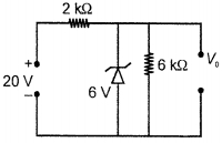
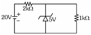
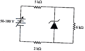
What is the value of output voltage $V_0$ in $V$ for the circuit shown in the figure?
A
$6$
B
$14$
C
$20$
D
$26$
Solution
(A) The circuit consists of a $20 \, V$ $DC$ source,a series resistor of $2 \, k\Omega$,a Zener diode with a breakdown voltage of $6 \, V$,and a load resistor of $6 \, k\Omega$ connected in parallel to the Zener diode.
When the Zener diode is in the breakdown region,it acts as a constant voltage source equal to its breakdown voltage.
Since the Zener diode is connected in parallel with the load resistor and the output terminals,the voltage across the load resistor is equal to the Zener breakdown voltage.
Therefore,the output voltage $V_0$ is equal to the Zener breakdown voltage,which is $6 \, V$.
0 likes
View Solution63
MediumMCQ
Choose the correct statement about $Zener$ diode.
A
It works as a voltage regulator in reverse bias and behaves like a simple $P-n$ junction diode in forward bias.
B
It works as a voltage regulator in both forward and reverse bias.
C
It works as a voltage regulator only in forward bias.
D
It works as a voltage regulator in forward bias and behaves like a simple $P-n$ junction diode in reverse bias.
Solution
(A) $Zener$ diode is specifically designed to operate in the reverse breakdown region.
When connected in reverse bias,it maintains a constant voltage across its terminals despite changes in the input voltage or load current,thus acting as a voltage regulator.
In forward bias,it behaves exactly like a standard $P-n$ junction diode,conducting current once the forward voltage exceeds the barrier potential.
0 likes
View Solution64
MediumMCQ
The incorrect statement about the property of a Zener diode is
A
Zener voltage remains constant at breakdown
B
It is designed to operate under reverse bias
C
Depletion region formed is very wide
D
$p$ and $n$ regions of Zener diode are heavily doped
Solution
(C) Zener diode is a special type of diode designed to operate reliably in the reverse breakdown region.
$1$. Doping: Zener diodes are heavily doped,which results in a very thin depletion region.
$2$. Depletion Region: Due to heavy doping,the depletion region is extremely thin (typically $10^{-6} \ m$),which allows for a high electric field even at low reverse voltages.
$3$. Operation: It is specifically designed to operate in the reverse bias region.
$4$. Voltage: Once the breakdown voltage is reached,the Zener voltage $(V_z)$ remains constant despite changes in the current.
Therefore,the statement that the depletion region is very wide is incorrect.
0 likes
View Solution65
MediumMCQ
$A$ Zener diode of power rating $1.6\,W$ is to be used as a voltage regulator. If the Zener diode has a breakdown voltage of $8\,V$ and it has to regulate an input voltage fluctuating between $3\,V$ and $10\,V$, the value of series resistance $R_s$ for the safe operation of the diode will be $.........\Omega$.
A
$13.3$
B
$12$
C
$10$
D
$13$
Solution
(C) The power rating of the Zener diode is $P = 1.6\,W$ and the breakdown voltage is $V_z = 8\,V$.
The maximum current that can flow through the Zener diode is $I_{z,max} = \frac{P}{V_z} = \frac{1.6\,W}{8\,V} = 0.2\,A$.
For the Zener diode to act as a voltage regulator, the input voltage $V_{in}$ must be greater than the breakdown voltage $V_z$. Here, the input voltage fluctuates between $3\,V$ and $10\,V$. The Zener diode will only regulate when $V_{in} \geq 8\,V$. Therefore, we consider the maximum input voltage $V_{in,max} = 10\,V$ to ensure the diode does not exceed its power rating.
The voltage drop across the series resistance $R_s$ at maximum input voltage is $V_{R_s} = V_{in,max} - V_z = 10\,V - 8\,V = 2\,V$.
To ensure safe operation, the current through the series resistance $R_s$ must be equal to the maximum current the Zener diode can handle (assuming no load current is connected, which is the worst-case scenario for the diode).
Thus, $R_s = \frac{V_{R_s}}{I_{z,max}} = \frac{2\,V}{0.2\,A} = 10\,\Omega$.
0 likes
View Solution66
DifficultMCQ
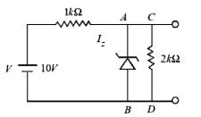
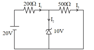
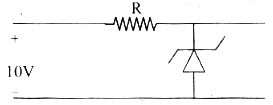
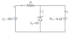
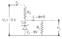
In the given circuit, the breakdown voltage of the Zener diode is $3.0 \, V$. What is the value of $I_z$ (in $ \, mA$)?
A
$3.3$
B
$5.5$
C
$10$
D
$7$
Solution
(B) Given, the breakdown voltage of the Zener diode is $V_z = 3.0 \, V$.
The total voltage supplied is $V = 10 \, V$ and the series resistance is $R_s = 1 \, k\Omega = 1000 \, \Omega$.
The current $I$ flowing through the series resistor is given by:
$I = \frac{V - V_z}{R_s} = \frac{10 \, V - 3 \, V}{1000 \, \Omega} = \frac{7 \, V}{1000 \, \Omega} = 7 \, mA$.
The load resistor is $R_L = 2 \, k\Omega = 2000 \, \Omega$. The current $I_L$ flowing through the load resistor is:
$I_L = \frac{V_z}{R_L} = \frac{3 \, V}{2000 \, \Omega} = 1.5 \, mA$.
Applying Kirchhoff's Current Law at node $A$, we have:
$I = I_z + I_L$
$I_z = I - I_L = 7 \, mA - 1.5 \, mA = 5.5 \, mA$.
Thus, the value of $I_z$ is $5.5 \, mA$.
0 likes
View Solution67
DifficultMCQ
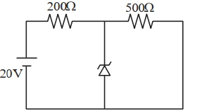
$A$ Zener diode of breakdown voltage $10 \, V$ is used as a voltage regulator as shown in the figure. The current through the Zener diode is (in $ \, mA$)
A
$50$
B
$0$
C
$30$
D
$20$
Solution
(C) The Zener diode is in the breakdown region, so the voltage across it is constant at $10 \, V$.
The current through the $500 \, \Omega$ load resistor $(I_L)$ is:
$I_L = \frac{V_Z}{R_L} = \frac{10 \, V}{500 \, \Omega} = 0.02 \, A = 20 \, mA$
The current through the series resistor $(I_S)$ is:
$I_S = \frac{V_{in} - V_Z}{R_S} = \frac{20 \, V - 10 \, V}{200 \, \Omega} = \frac{10 \, V}{200 \, \Omega} = 0.05 \, A = 50 \, mA$
Applying Kirchhoff's Current Law at the junction, the current through the Zener diode $(I_Z)$ is:
$I_Z = I_S - I_L = 50 \, mA - 20 \, mA = 30 \, mA$
0 likes
View Solution68
DifficultMCQ
In the given circuit, if the power rating of the Zener diode is $10 \, mW$, the value of series resistance $R_s$ to regulate the input unregulated supply is:
A
$0.6 \, k \Omega$
B
$10 \, \Omega$
C
$1 \, k \Omega$
D
$10 \, k \Omega$
Solution
(NONE) The voltage drop across the series resistor $R_s$ is given by:
$V_s = V_{in} - V_z = 8 \, V - 5 \, V = 3 \, V$
The current through the load resistor $R_L$ is:
$I_L = \frac{V_z}{R_L} = \frac{5 \, V}{1 \times 10^3 \, \Omega} = 5 \, mA$
The maximum current through the Zener diode is determined by its power rating $P_z = 10 \, mW$:
$I_{z,max} = \frac{P_z}{V_z} = \frac{10 \, mW}{5 \, V} = 2 \, mA$
For the Zener diode to regulate, the current through the series resistor $I_s$ must be sufficient to supply the load current and the Zener current. The total current $I_s$ is $I_L + I_z$.
To find the required $R_s$, we use the condition $I_{s} = I_L + I_z$.
For the circuit to function as a regulator, the current through the Zener diode must be between $0$ and $I_{z,max}$.
Thus, $I_{s,min} = I_L + 0 = 5 \, mA$ and $I_{s,max} = I_L + I_{z,max} = 5 \, mA + 2 \, mA = 7 \, mA$.
The resistance $R_s$ must satisfy:
$R_{s,min} = \frac{V_s}{I_{s,max}} = \frac{3 \, V}{7 \, mA} = \frac{3}{7} \, k \Omega \approx 0.43 \, k \Omega$
$R_{s,max} = \frac{V_s}{I_{s,min}} = \frac{3 \, V}{5 \, mA} = 0.6 \, k \Omega$
Given the options, none match the calculated range exactly, but $R_s$ must be chosen to ensure the Zener diode operates within its limits. Typically, such questions look for a value within the range or a specific design constraint.
0 likes
View Solution69
DifficultMCQ
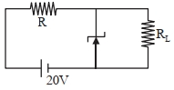
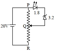
$A$ potential divider circuit is connected to a $DC$ source of $20 \,V$, a light emitting diode $(LED)$ with a glow-in voltage of $1.8 \,V$, and a Zener diode with a breakdown voltage of $3.2 \,V$. The total length $(PR)$ of the resistive wire is $20 \,cm$. The minimum length of $PQ$ required for the $LED$ to just glow is ............. $cm$.
A
$2$
B
$3$
C
$4$
D
$5$
Solution
(D) For the $LED$ to just glow, the potential difference across the segment $PQ$ must be equal to the sum of the threshold voltage of the $LED$ and the breakdown voltage of the Zener diode.
$V_{PQ} = V_{LED} + V_{Zener}$
$V_{PQ} = 1.8 \,V + 3.2 \,V = 5.0 \,V$
The potential divider circuit has a total voltage of $20 \,V$ across the total length $PR = 20 \,cm$.
Using the principle of a potential divider, the voltage across a segment is proportional to its length:
$\frac{V_{PQ}}{V_{PR}} = \frac{PQ}{PR}$
$\frac{5 \,V}{20 \,V} = \frac{PQ}{20 \,cm}$
$PQ = \left( \frac{5}{20} \right) \times 20 \,cm = 5 \,cm$
Thus, the minimum length of $PQ$ required is $5 \,cm$.
0 likes
View Solution70
DifficultMCQ
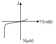
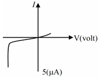
The $I-V$ characteristics of an electronic device are shown in the figure. The device is:
A
a solar cell
B
a transistor which can be used as an amplifier
C
a zener diode which can be used as a voltage regulator
D
a diode which can be used as a rectifier
Solution
(C) The given $I-V$ characteristic curve shows a sharp breakdown in the reverse bias region at a specific voltage.
This behavior is characteristic of a Zener diode.
$A$ Zener diode is specifically designed to operate in the reverse breakdown region without being damaged.
Due to this property,it is widely used as a voltage regulator to maintain a constant output voltage across a load despite variations in input voltage or load current.
0 likes
View Solution71
DifficultMCQ
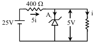
$A$ Zener diode with $5\ V$ Zener voltage is used to regulate an unregulated $DC$ voltage input of $25\ V$. For a $400\ \Omega$ resistor connected in series, the Zener current is found to be $4$ times the load current. The load current $(I_L)$ and load resistance $(R_L)$ are:
A
$I_L = 20\ mA; R_L = 250\ \Omega$
B
$I_L = 10\ A; R_L = 0.5\ \Omega$
C
$I_L = 0.02\ mA; R_L = 250\ \Omega$
D
$I_L = 10\ mA; R_L = 500\ \Omega$
Solution
(D) Let the load current be $I_L = i$.
According to the problem, the Zener current $I_Z = 4I_L = 4i$.
The total current flowing through the series resistor is $I = I_Z + I_L = 4i + i = 5i$.
The voltage across the series resistor is $V_R = V_{in} - V_Z = 25\ V - 5\ V = 20\ V$.
Using Ohm's law for the series resistor: $V_R = I \times R_s$
$20\ V = (5i) \times 400\ \Omega$
$20 = 2000i$
$i = \frac{20}{2000} = 0.01\ A = 10\ mA$.
Thus, the load current $I_L = 10\ mA$.
The load resistance $R_L$ is given by $R_L = \frac{V_L}{I_L} = \frac{5\ V}{10 \times 10^{-3}\ A} = 500\ \Omega$.
0 likes
View Solution72
MediumMCQ
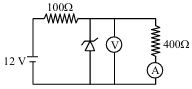
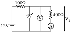
In the following circuit,the reading of the ammeter will be (Take Zener breakdown voltage $= 4 \ V$) (in $mA$)
A
$24$
B
$80$
C
$10$
D
$60$
Solution
(C) First,we check if the Zener diode is in breakdown by calculating the voltage across the parallel branch without the Zener diode:
$V_{open} = \frac{400 \ \Omega}{100 \ \Omega + 400 \ \Omega} \times 12 \ V = \frac{400}{500} \times 12 \ V = 0.8 \times 12 \ V = 9.6 \ V$.
Since the calculated voltage $9.6 \ V$ is greater than the Zener breakdown voltage $V_z = 4 \ V$,the Zener diode operates in the breakdown region.
Therefore,the voltage across the $400 \ \Omega$ resistor is fixed at the Zener voltage,$V = 4 \ V$.
The current $I$ through the ammeter is given by Ohm's law:
$I = \frac{V}{R} = \frac{4 \ V}{400 \ \Omega} = 0.01 \ A = 10 \ mA$.
0 likes
View Solution73
MediumMCQ
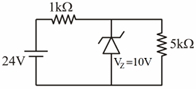
For the given circuit, the power across the Zener diode is $....... \text{mW}$.
A
$100$
B
$110$
C
$120$
D
$130$
Solution
(C) The circuit consists of a source voltage $V = 24 \text{ V}$, a series resistor $R_s = 1 \text{ k}\Omega$, a Zener diode with breakdown voltage $V_z = 10 \text{ V}$, and a load resistor $R_L = 5 \text{ k}\Omega$.
$1$. The current through the series resistor $R_s$ is given by:
$I_s = \frac{V - V_z}{R_s} = \frac{24 \text{ V} - 10 \text{ V}}{1 \times 10^3 \text{ }\Omega} = \frac{14 \text{ V}}{1000 \text{ }\Omega} = 14 \text{ mA}$.
$2$. The current through the load resistor $R_L$ is:
$I_L = \frac{V_z}{R_L} = \frac{10 \text{ V}}{5 \times 10^3 \text{ }\Omega} = 2 \text{ mA}$.
$3$. The current through the Zener diode $I_z$ is:
$I_z = I_s - I_L = 14 \text{ mA} - 2 \text{ mA} = 12 \text{ mA}$.
$4$. The power dissipated across the Zener diode $P_z$ is:
$P_z = V_z \times I_z = 10 \text{ V} \times 12 \text{ mA} = 120 \text{ mW}$.
0 likes
View Solution74
MediumMCQ
In the given circuit,the value of $I_{L}$ (in $mA$) will be: (in $.5$)
A
$2$
B
$1$
C
$3$
D
$4$
Solution
(A) The Zener diode is connected in parallel with the load resistor $R_{L} = 2 \ k\Omega = 2000 \ \Omega$.
Since the Zener diode is in the breakdown region,the voltage across the load resistor $R_{L}$ is equal to the Zener voltage $V_{Z} = 5 \ V$.
Using Ohm's law,the current through the load resistor $I_{L}$ is given by:
$I_{L} = \frac{V_{Z}}{R_{L}}$
$I_{L} = \frac{5 \ V}{2000 \ \Omega} = 0.0025 \ A$
Converting to milliamperes $(mA)$:
$I_{L} = 0.0025 \times 1000 \ mA = 2.5 \ mA$.
0 likes
View Solution75
MediumMCQ
Find the current through the Zener diode in the given circuit. (in $mA$)
A
$5$
B
$7.5$
C
$2.5$
D
$12.5$
Solution
(C) The input voltage is $V_{in} = 20 \ V$ and the series resistance is $R_s = 2 \ k\Omega$. The Zener diode maintains a constant voltage of $V_z = 5 \ V$ across the load resistor $R_L = 1 \ k\Omega$.
The total current flowing from the source is:
$I_{in} = \frac{V_{in} - V_z}{R_s} = \frac{20 \ V - 5 \ V}{2 \times 10^3 \ \Omega} = \frac{15 \ V}{2000 \ \Omega} = 7.5 \ mA$.
The current flowing through the load resistor $R_L$ is:
$I_L = \frac{V_z}{R_L} = \frac{5 \ V}{1 \times 10^3 \ \Omega} = 5 \ mA$.
Applying Kirchhoff's Current Law at the node, the current through the Zener diode $I_Z$ is:
$I_Z = I_{in} - I_L = 7.5 \ mA - 5 \ mA = 2.5 \ mA$.
0 likes
View Solution76
EasyMCQ
The $I-V$ characteristics of an electronic device are shown in the figure. The device is $:-$
A
a solar cell
B
a light emitting diode
C
a zener diode which can be used as a voltage regulator
D
None of the above
Solution
(C) The given $I-V$ characteristic curve shows a sharp breakdown in the reverse bias region (third quadrant).
This behavior is characteristic of a Zener diode.
$A$ Zener diode is specifically designed to operate in the reverse breakdown region,where it maintains a nearly constant voltage across its terminals despite changes in the current flowing through it.
Therefore,it is widely used as a voltage regulator.
0 likes
View Solution77
EasyMCQ
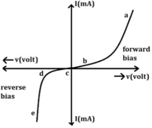
The graph given below represents $I-V$ characteristics of a Zener diode. The part of the characteristics curve that is most relevant for its operation as a voltage regulator is
A
ab
B
bc
C
cd
D
de
Solution
(D) Zener diode is a special type of diode designed to operate in the reverse breakdown region.
When a Zener diode is reverse-biased,it maintains a nearly constant voltage across its terminals even as the current through it changes significantly.
This property is utilized for voltage regulation.
In the given $I-V$ characteristic curve,the region $de$ represents the reverse breakdown region where the current increases rapidly while the voltage remains nearly constant.
Therefore,the part $de$ is most relevant for its operation as a voltage regulator.
0 likes
View Solution78
EasyMCQ
When the Zener diode is used as a voltage regulator,it is connected in
A
reverse bias and in series with load.
B
forward bias and in series with load.
C
forward bias and in parallel with load.
D
reverse bias and in parallel with load.
Solution
(D) Zener diode is specifically designed to operate in the breakdown region. When used as a voltage regulator,it is connected in reverse bias across the load. This configuration allows the Zener diode to maintain a constant voltage across the load,even if the input voltage or load current changes. Therefore,the correct connection is reverse bias and in parallel with the load.
0 likes
View Solution79
DifficultMCQ
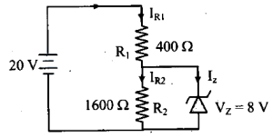
In the following circuit,the current flowing through the Zener diode is (in $\text{ mA}$)
A
$35$
B
$25$
C
$15$
D
$5$
Solution
(B) The Zener diode is connected in parallel with resistor $R_2$. Therefore,the voltage across $R_2$ is equal to the Zener breakdown voltage,$V_Z = 8 \text{ V}$.
The current flowing through resistor $R_2$ is:
$I_{R_2} = \frac{V_Z}{R_2} = \frac{8 \text{ V}}{1600 \text{ }\Omega} = 5 \times 10^{-3} \text{ A} = 5 \text{ mA} \quad \dots(i)$
The total voltage supplied is $20 \text{ V}$. The voltage drop across resistor $R_1$ is:
$V_{R_1} = V_{\text{source}} - V_Z = 20 \text{ V} - 8 \text{ V} = 12 \text{ V}$
The total current flowing through the circuit (which passes through $R_1$) is:
$I_{R_1} = \frac{V_{R_1}}{R_1} = \frac{12 \text{ V}}{400 \text{ }\Omega} = 3 \times 10^{-2} \text{ A} = 30 \text{ mA} \quad \dots(ii)$
Applying Kirchhoff's Current Law at the junction,the current through the Zener diode $I_Z$ is:
$I_Z = I_{R_1} - I_{R_2}$
$I_Z = 30 \text{ mA} - 5 \text{ mA} = 25 \text{ mA}$
0 likes
View Solution80
EasyMCQ
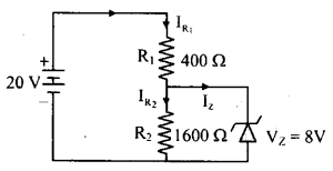
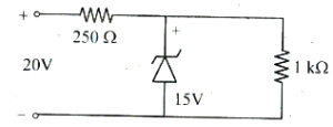
$A$ Zener diode, having a breakdown voltage of $15 \text{ V}$, is used in a voltage regulator circuit as shown. The current through the Zener diode is (in $\text{ mA}$)
A
$20$
B
$5$
C
$10$
D
$15$
Solution
(B) The Zener diode is in parallel with the load resistor of $1 \text{ k}\Omega$. Since the Zener breakdown voltage is $15 \text{ V}$, the voltage across the load resistor is $V_L = 15 \text{ V}$.
The current through the load resistor is $I_L = \frac{V_L}{R_L} = \frac{15 \text{ V}}{1000 \Omega} = 15 \times 10^{-3} \text{ A} = 15 \text{ mA}$.
The voltage drop across the series resistor $R_s = 250 \Omega$ is $V_s = V_{in} - V_L = 20 \text{ V} - 15 \text{ V} = 5 \text{ V}$.
The total current supplied by the source is $I = \frac{V_s}{R_s} = \frac{5 \text{ V}}{250 \Omega} = 0.02 \text{ A} = 20 \text{ mA}$.
Applying Kirchhoff's Current Law at the junction, the current through the Zener diode $I_z$ is $I_z = I - I_L = 20 \text{ mA} - 15 \text{ mA} = 5 \text{ mA}$.
0 likes
View Solution81
DifficultMCQ
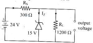
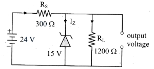
In the circuit diagram shown in the figure,the current through the zener diode is (in $mA$)
A
$30$
B
$17.5$
C
$15$
D
$12.5$
Solution
(B) The zener diode is in parallel with the load resistor $R_L = 1200 \Omega$. Since the zener breakdown voltage is $15 \text{ V}$,the voltage across the load resistor is $V_L = 15 \text{ V}$.
The current through the load resistor is $I_L = \frac{V_L}{R_L} = \frac{15 \text{ V}}{1200 \Omega} = 0.0125 \text{ A} = 12.5 \text{ mA}$.
The voltage across the series resistor $R_S = 300 \Omega$ is $V_S = V_{in} - V_L = 24 \text{ V} - 15 \text{ V} = 9 \text{ V}$.
The total current supplied by the source is $I = \frac{V_S}{R_S} = \frac{9 \text{ V}}{300 \Omega} = 0.03 \text{ A} = 30 \text{ mA}$.
Applying Kirchhoff's Current Law at the junction,the current through the zener diode $I_Z$ is given by $I_Z = I - I_L$.
$I_Z = 30 \text{ mA} - 12.5 \text{ mA} = 17.5 \text{ mA}$.
0 likes
View Solution82
EasyMCQ
In the given circuit,the Zener breakdown voltage is $8 \ V$. If the power of the Zener diode is $1.6 \ W$,the value of $R$ is (in $\Omega$)
A
$2$
B
$4$
C
$6$
D
$10$
Solution
(D) Given: Zener breakdown voltage $V_Z = 8 \ V$,Power $P = 1.6 \ W$,Input voltage $V_{in} = 10 \ V$.
$1$. Calculate the current through the Zener diode $(I_Z)$:
$P = V_Z \times I_Z$
$1.6 = 8 \times I_Z$
$I_Z = \frac{1.6}{8} = 0.2 \ A$
$2$. Calculate the voltage drop across the resistor $R$ $(V_R)$:
Since the Zener diode is in parallel with the output,the voltage across it is constant at $8 \ V$.
$V_R = V_{in} - V_Z = 10 \ V - 8 \ V = 2 \ V$
$3$. Calculate the resistance $R$:
Using Ohm's law,$V_R = I_Z \times R$
$2 = 0.2 \times R$
$R = \frac{2}{0.2} = 10 \ \Omega$
Therefore,the value of $R$ is $10 \ \Omega$.
0 likes
View Solution83
DifficultMCQ
$A$ $5.0 \, V$ stabilized power supply is required to be designed using a $12 \, V$ $DC$ power supply as an input source. The maximum power rating of the zener diode is $2.0 \, W$. The minimum value of resistance $R_{s}$ in $\Omega$ connected in series with the zener diode will be (in $.5$)
A
$16$
B
$17$
C
$18$
D
$15$
Solution
(B) The zener diode operates at a constant voltage $V_{Z} = 5.0 \, V$.
Given the input voltage $V_{S} = 12 \, V$ and the maximum power rating $P_{Z} = 2.0 \, W$.
The maximum current $I_{Z_{\max}}$ that the zener diode can handle is calculated as:
$I_{Z_{\max}} = \frac{P_{Z}}{V_{Z}} = \frac{2.0 \, W}{5.0 \, V} = 0.4 \, A = 400 \, mA$.
The series resistance $R_{S}$ is used to drop the excess voltage $(V_{S} - V_{Z})$ and limit the current to $I_{Z_{\max}}$.
$R_{S} = \frac{V_{S} - V_{Z}}{I_{Z_{\max}}} = \frac{12 \, V - 5.0 \, V}{0.4 \, A} = \frac{7}{0.4} \, \Omega = 17.5 \, \Omega$.
0 likes
View Solution84
EasyMCQ
In a Zener diode,the reverse bias voltage is $3 \ V$ and the width of the depletion region is $300 \ \mathring{A}$. The electric field intensity will be $\dots \ V/cm$.
A
$10^{4}$
B
$10^{6}$
C
$10^{8}$
D
$10^{-2}$
Solution
(B) The electric field intensity $E$ is given by the formula $E = \frac{V}{d}$,where $V$ is the potential difference and $d$ is the width of the depletion region.
Given: $V = 3 \ V$ and $d = 300 \ \mathring{A} = 300 \times 10^{-8} \ cm$.
Substituting the values:
$E = \frac{3}{300 \times 10^{-8}} \ V/cm$
$E = \frac{3}{3 \times 10^{-6}} \ V/cm$
$E = 10^{6} \ V/cm$.
Therefore,the correct option is $B$.
Given: $V = 3 \ V$ and $d = 300 \ \mathring{A} = 300 \times 10^{-8} \ cm$.
Substituting the values:
$E = \frac{3}{300 \times 10^{-8}} \ V/cm$
$E = \frac{3}{3 \times 10^{-6}} \ V/cm$
$E = 10^{6} \ V/cm$.
Therefore,the correct option is $B$.
0 likes
View Solution85
MediumMCQ
Which of the following semi-conducting devices is used as a voltage regulator?
A
Photo diode
B
$LASER$ diode
C
Zener diode
D
Solar cell
Solution
(C) voltage regulator is an electronic circuit that provides a stable $DC$ voltage independent of load current,temperature,and $AC$ line voltage variations.
Specifically,a $Zener$ diode is designed to operate in the reverse breakdown region,allowing it to maintain a constant voltage across its terminals despite changes in input voltage or load current.
Therefore,the $Zener$ diode is widely used as a voltage regulator.
Specifically,a $Zener$ diode is designed to operate in the reverse breakdown region,allowing it to maintain a constant voltage across its terminals despite changes in input voltage or load current.
Therefore,the $Zener$ diode is widely used as a voltage regulator.
0 likes
View Solution86
MediumMCQ
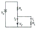
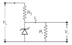
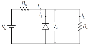
In the diagram shown,the Zener diode has a reverse breakdown voltage of $V_Z$. The current through the load resistance $R_L$ is $I_L$. The current through the Zener diode is
A
$\frac{V_0-V_Z}{R_S}$
B
$\frac{V_0-V_Z}{R_L}$
C
$\frac{V_Z}{R_L}$
D
$\left(\frac{V_0-V_Z}{R_S}\right)-I_L$
Solution
(D) From the circuit diagram,the total current $I$ flowing through the series resistor $R_S$ is given by the voltage drop across it divided by its resistance:
$I = \frac{V_0 - V_Z}{R_S}$
According to Kirchhoff's current law at the junction point,the total current $I$ splits into the Zener diode current $I_Z$ and the load current $I_L$:
$I = I_Z + I_L$
Rearranging this equation to solve for the Zener diode current $I_Z$:
$I_Z = I - I_L$
Substituting the expression for $I$:
$I_Z = \left(\frac{V_0 - V_Z}{R_S}\right) - I_L$
0 likes
View Solution87
MediumMCQ
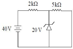
$A$ Zener diode of breakdown voltage $20 \ V$ is connected as shown in the given circuit. The current through the Zener diode is (in $mA$)
A
$10$
B
$4$
C
$6$
D
$8$
Solution
(C) The circuit consists of a $40 \ V$ $DC$ source,a series resistor $R_s = 2 \ k\Omega$,a Zener diode with breakdown voltage $V_z = 20 \ V$,and a load resistor $R_L = 5 \ k\Omega$.
First,calculate the total current $I$ flowing through the series resistor $R_s$:
$I = \frac{V_{source} - V_z}{R_s} = \frac{40 \ V - 20 \ V}{2 \ k\Omega} = \frac{20 \ V}{2 \times 10^3 \ \Omega} = 10 \times 10^{-3} \ A = 10 \ mA$.
Next,calculate the load current $I_L$ flowing through the load resistor $R_L$:
$I_L = \frac{V_z}{R_L} = \frac{20 \ V}{5 \ k\Omega} = \frac{20 \ V}{5 \times 10^3 \ \Omega} = 4 \times 10^{-3} \ A = 4 \ mA$.
The current through the Zener diode $I_z$ is given by the difference between the total current and the load current:
$I_z = I - I_L = 10 \ mA - 4 \ mA = 6 \ mA$.
Therefore,the correct option is $C$.
0 likes
View Solution88
EasyMCQ
The device used for voltage regulation is
A
Zener diode
B
photo diode
C
light emitting diode
D
solar cell
Solution
(A) $Zener$ $diode$ is a special type of $PN$ junction diode designed to operate in the reverse breakdown region.
When the reverse voltage across a $Zener$ $diode$ reaches the $Zener$ breakdown voltage,the voltage across it remains constant even if the current through it changes significantly.
This property makes it ideal for use as a voltage regulator in electronic circuits to maintain a stable output voltage.
0 likes
View Solution89
EasyMCQ
$A$ reverse biased Zener diode when operated in the breakdown region works as
A
an amplifier
B
an oscillator
C
a voltage regulator
D
a rectifier
Solution
(C) When a Zener diode is reverse biased and operated in the breakdown region,the voltage across it remains constant even if the current through it changes significantly.
Due to this property,it is widely used as a voltage regulator to maintain a steady output voltage across a load.
Due to this property,it is widely used as a voltage regulator to maintain a steady output voltage across a load.
0 likes
View Solution90
EasyMCQ
If the current in the Zener diode is five times the current in $R_1$ and the breakdown voltage of the diode is $6 \text{ V}$,find the value of $R$.
A
$2000 \text{ } \Omega$
B
$\frac{2000}{3} \text{ } \Omega$
C
$1000 \text{ } \Omega$
D
$\frac{1000}{3} \text{ } \Omega$
Solution
(B) Given that,$R_1 = 1 \text{ k}\Omega = 1000 \text{ } \Omega$,and Zener breakdown voltage $V_z = 6 \text{ V}$.
Let $I_1$ be the current through $R_1$ and $I_z$ be the current through the Zener diode.
Since $R_1$ is in parallel with the Zener diode,the voltage across $R_1$ is $V_z = 6 \text{ V}$.
Therefore,$I_1 = \frac{V_z}{R_1} = \frac{6 \text{ V}}{1000 \text{ } \Omega} = 6 \times 10^{-3} \text{ A}$.
According to the given condition,the Zener current is $I_z = 5 I_1 = 5 \times (6 \times 10^{-3} \text{ A}) = 30 \times 10^{-3} \text{ A}$.
The total current $I$ drawn from the source $V_s = 30 \text{ V}$ is $I = I_1 + I_z = 6 \times 10^{-3} + 30 \times 10^{-3} = 36 \times 10^{-3} \text{ A}$.
Also,the voltage drop across $R$ is $V_s - V_z = 30 \text{ V} - 6 \text{ V} = 24 \text{ V}$.
Using Ohm's law,$R = \frac{V_s - V_z}{I} = \frac{24}{36 \times 10^{-3}} = \frac{24000}{36} \text{ } \Omega = \frac{2000}{3} \text{ } \Omega$.
0 likes
View Solution91
EasyMCQ
$A$ Zener diode is made by
A
heavily doping both $p$- and $n$-sides of a $p-n$ junction diode
B
heavily doping the $p$-side and lightly doping the $n$-side of a $p-n$ junction diode
C
lightly doping the $p$-side and heavily doping the $n$-side of a $p-n$ junction diode
D
lightly doping both $p$- and $n$-sides of a $p-n$ junction diode
Solution
(A) Zener diode is designed to operate in the reverse breakdown region.
To achieve this, the $p-n$ junction is heavily doped on both sides.
Due to this heavy doping, the depletion region becomes extremely thin (less than $10^{-6} \,m$).
This thin depletion layer results in a very high electric field across the junction even for a small reverse bias voltage, which facilitates Zener breakdown.
0 likes
View Solution92
EasyMCQ
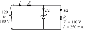
$A$ Zener diode voltage regulator operated in the range $120 \, V - 180 \, V$ produces a constant supply of $110 \, V$ and $250 \, mA$ to the load. If the maximum current is equally shared between the load and the Zener diode, then the values of load resistance $(R_L)$ and series resistance $(R_S)$ are respectively
A
$R_L = 280 \, \Omega, R_S = 70 \, \Omega$
B
$R_L = 440 \, \Omega, R_S = 140 \, \Omega$
C
$R_L = 70 \, \Omega, R_S = 280 \, \Omega$
D
$R_L = 440 \, \Omega, R_S = 1400 \, \Omega$
Solution
(B) The load resistance $R_L$ is given by $R_L = \frac{V_L}{I_L} = \frac{110 \, V}{250 \times 10^{-3} \, A} = 440 \, \Omega$.
Given that the maximum current $I$ is equally shared between the load and the Zener diode, we have $I_Z = I_L = 250 \, mA$.
Therefore, the total maximum current is $I = I_L + I_Z = 250 \, mA + 250 \, mA = 500 \, mA = 0.5 \, A$.
The series resistance $R_S$ is calculated at the maximum input voltage $V_{in,max} = 180 \, V$ as $R_S = \frac{V_{in,max} - V_L}{I} = \frac{180 \, V - 110 \, V}{0.5 \, A} = \frac{70 \, V}{0.5 \, A} = 140 \, \Omega$.
Thus, $R_L = 440 \, \Omega$ and $R_S = 140 \, \Omega$.
0 likes
View Solution93
EasyMCQ
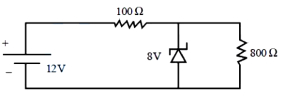
In the following circuit,the power dissipated in the Zener diode is (in $W$)
A
$0.12$
B
$0.18$
C
$0.24$
D
$0.36$
Solution
(C) Given: Source voltage $V_s = 12 \ V$,series resistance $R_s = 100 \ \Omega$,Zener voltage $V_z = 8 \ V$,load resistance $R_L = 800 \ \Omega$.
The current through the series resistor $R_s$ is given by:
$I_s = \frac{V_s - V_z}{R_s} = \frac{12 \ V - 8 \ V}{100 \ \Omega} = \frac{4 \ V}{100 \ \Omega} = 0.04 \ A = 40 \ mA$.
The current through the load resistor $R_L$ is:
$I_L = \frac{V_z}{R_L} = \frac{8 \ V}{800 \ \Omega} = 0.01 \ A = 10 \ mA$.
The current through the Zener diode $I_z$ is:
$I_z = I_s - I_L = 40 \ mA - 10 \ mA = 30 \ mA = 0.03 \ A$.
The power dissipated in the Zener diode is:
$P_z = V_z \times I_z = 8 \ V \times 0.03 \ A = 0.24 \ W$.
0 likes
View Solution94
EasyMCQ
$A$ Zener diode with a Zener voltage of $30 \text{ V}$ is connected in a circuit as shown in the figure. The maximum current through the Zener diode is: (in $\text{ mA}$)
A
$5$
B
$14$
C
$9$
D
$7$
Solution
(A) Step $1$: Current through Load Resistor $(I_L)$
Since the Zener diode regulates the voltage at $30 \text{ V}$,the voltage across the load resistor $(R_L = 6 \text{ k}\Omega)$ will also be $30 \text{ V}$.
The current through the load resistor,$I_L$,is:
$I_L = \frac{V_Z}{R_L} = \frac{30 \text{ V}}{6 \text{ k}\Omega} = 5 \text{ mA}$
Step $2$: Total Current in the Circuit $(I_{\text{total}})$
The total current supplied by the source,$I_{\text{total}}$,is given by:
$I_{\text{total}} = \frac{V_{\text{in}} - V_Z}{R_{\text{total}}}$
where $R_{\text{total}} = 5 \text{ k}\Omega + 2 \text{ k}\Omega = 7 \text{ k}\Omega$.
For maximum $I_{\text{total}}$,we use the maximum input voltage $V_{\text{in}} = 100 \text{ V}$:
$I_{\text{total}} = \frac{100 \text{ V} - 30 \text{ V}}{7 \text{ k}\Omega} = \frac{70 \text{ V}}{7 \text{ k}\Omega} = 10 \text{ mA}$
Step $3$: Maximum Zener Diode Current $(I_{Z \max})$
The Zener diode current $I_Z$ is the difference between the total current and the load current:
$I_{Z \max} = I_{\text{total}} - I_L = 10 \text{ mA} - 5 \text{ mA} = 5 \text{ mA}$
Final Answer:
The maximum current through the Zener diode is $5 \text{ mA}$.
0 likes
View Solution95
MediumMCQ
In a Zener regulated power supply, a Zener diode with $V_z = 6 \, V$ is used for regulation. The load current is $4 \, mA$ and the unregulated input voltage is $10 \, V$. To get a Zener current five times the load current, the value of the series resistor $R_S$ is nearly:
A
$150 \, \Omega$
B
$167 \, \Omega$
C
$175 \, \Omega$
D
$159 \, \Omega$
Solution
(B) Given: Zener voltage $V_z = 6 \, V$, load current $I_L = 4 \, mA$, and input voltage $V_{in} = 10 \, V$.
We are given that the Zener current $I_Z$ is five times the load current $I_L$.
So, $I_Z = 5 \times I_L = 5 \times 4 \, mA = 20 \, mA$.
The total current $I_S$ flowing through the series resistor $R_S$ is the sum of the Zener current and the load current:
$I_S = I_Z + I_L = 20 \, mA + 4 \, mA = 24 \, mA = 24 \times 10^{-3} \, A$.
The potential drop across the series resistor $R_S$ is the difference between the input voltage and the Zener voltage:
$V_S = V_{in} - V_z = 10 \, V - 6 \, V = 4 \, V$.
Using Ohm's law, the value of the series resistor $R_S$ is:
$R_S = \frac{V_S}{I_S} = \frac{4 \, V}{24 \times 10^{-3} \, A} = \frac{4000}{24} \, \Omega \approx 166.67 \, \Omega$.
Rounding to the nearest value, we get $R_S \approx 167 \, \Omega$.
0 likes
View Solution96
EasyMCQ
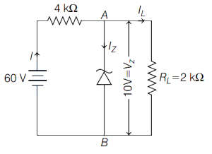
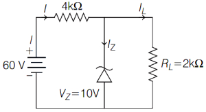
$A$ Zener diode is connected to a battery and a load resistance as shown below. The currents $I, I_Z$ and $I_L$ respectively are:
A
$10 \text{ mA}, 5 \text{ mA}, 5 \text{ mA}$
B
$15 \text{ mA}, 7.5 \text{ mA}, 7.5 \text{ mA}$
C
$12.5 \text{ mA}, 5 \text{ mA}, 7.5 \text{ mA}$
D
$12.5 \text{ mA}, 7.5 \text{ mA}, 5 \text{ mA}$
Solution
(D) The circuit is given as shown in the figure.
Potential drop across the load resistance $R_L$ is $V_L = V_Z = 10 \text{ V}$.
Potential drop across the $4 \text{ k}\Omega$ series resistance is $V_R = 60 \text{ V} - 10 \text{ V} = 50 \text{ V}$.
Current through the $4 \text{ k}\Omega$ resistance is $I = \frac{V_R}{R} = \frac{50 \text{ V}}{4 \times 10^3 \Omega} = 12.5 \times 10^{-3} \text{ A} = 12.5 \text{ mA}$.
Current through the load resistance $I_L$ is $I_L = \frac{V_L}{R_L} = \frac{10 \text{ V}}{2 \times 10^3 \Omega} = 5 \text{ mA}$.
Using Kirchhoff's current law at the node,$I = I_Z + I_L$,therefore $I_Z = I - I_L = 12.5 \text{ mA} - 5 \text{ mA} = 7.5 \text{ mA}$.
Thus,the currents are $I = 12.5 \text{ mA}$,$I_Z = 7.5 \text{ mA}$,and $I_L = 5 \text{ mA}$.
0 likes
View Solution97
EasyMCQ
In a Zener diode,
A
only $p$-region is heavily doped
B
only $n$-region is heavily doped
C
Both $p$ and $n$ regions are heavily doped
D
Both $p$ and $n$ regions are lightly doped
Solution
(C) Zener diode is a special type of semiconductor diode designed to operate in the reverse breakdown region.
To achieve a sharp breakdown voltage,both the $p$-region and the $n$-region of the Zener diode are heavily doped.
This heavy doping results in a very thin depletion layer.
When a reverse bias voltage is applied and reaches the breakdown voltage,the high electric field across the thin depletion layer causes a rapid increase in current due to Zener breakdown.
0 likes
View Solution98
MediumMCQ
When a Zener diode is used as a regulator with a Zener voltage of $10 \, V$, nearly five times the load current passes through the Zener diode. What should be the series resistance for the Zener diode if the load resistance is $2 \, k\Omega$ and the unregulated voltage supplied is $16 \, V$?
A
$500 \, \Omega$
B
$100 \, \Omega$
C
$200 \, \Omega$
D
$800 \, \Omega$
Solution
(C) The circuit diagram of a Zener diode as a voltage regulator is shown in the figure.
Given: Supply voltage $V_s = 16 \, V$, Zener voltage $V_Z = 10 \, V$, Zener current $I_Z = 5 I_L$, and load resistance $R_L = 2 \, k\Omega = 2000 \, \Omega$.
The current through the load resistance is:
$I_L = \frac{V_Z}{R_L} = \frac{10 \, V}{2000 \, \Omega} = 5 \times 10^{-3} \, A = 5 \, mA$.
The total current through the series resistance is:
$I = I_Z + I_L = 5 I_L + I_L = 6 I_L$.
$I = 6 \times (5 \, mA) = 30 \, mA = 3 \times 10^{-2} \, A$.
The series resistance $R_S$ is given by:
$R_S = \frac{V_S - V_Z}{I} = \frac{16 \, V - 10 \, V}{3 \times 10^{-2} \, A} = \frac{6 \, V}{0.03 \, A} = 200 \, \Omega$.
Thus, the series resistance for the Zener diode is $200 \, \Omega$.
0 likes
View Solution99
MediumMCQ
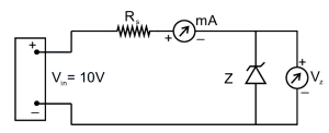
Manufacturers supply a zener diode with zener voltage $V_{z}=5.6 \, V$ and maximum power dissipation $P_{z \max }=\frac{1}{4} \, W$. This zener diode is used in the following circuit. Calculate the minimum value of the resistance $R_s$ in the circuit so that the zener diode will not burn when the input voltage is $V_{in}=10 \, V$. (in $\Omega$)
A
$98.56$
B
$170.52$
C
$306.21$
D
$412.37$
Solution
(A) Given:
Zener voltage $V_z = 5.6 \, V$
Maximum power dissipation $P_{z \max} = \frac{1}{4} \, W = 0.25 \, W$
Input voltage $V_{in} = 10 \, V$
The maximum current $I_z$ that the zener diode can handle is given by:
$P_{z \max} = V_z \times I_z$
$0.25 = 5.6 \times I_z$
$I_z = \frac{0.25}{5.6} \, A$
In the circuit, the current through the series resistance $R_s$ is $I_s = I_z$. The voltage drop across the resistance $R_s$ is:
$V_{R_s} = V_{in} - V_z = 10 \, V - 5.6 \, V = 4.4 \, V$
Using Ohm's law for the resistance $R_s$:
$R_s = \frac{V_{R_s}}{I_s} = \frac{4.4}{I_z} = \frac{4.4}{(0.25 / 5.6)}$
$R_s = \frac{4.4 \times 5.6}{0.25} = 4.4 \times 5.6 \times 4 = 98.56 \, \Omega$
Thus, the minimum value of the resistance $R_s$ is $98.56 \, \Omega$.
0 likes
View Solution100
EasyMCQ
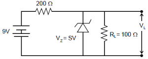
In the given circuit, find the voltage drop $V_L$ across the load resistance $R_L$. (in $V$)
A
$5$
B
$3$
C
$9$
D
$6$
Solution
(B) To determine if the Zener diode is conducting, we first calculate the voltage across the load resistance $R_L$ assuming the diode is open-circuited.
Using the voltage divider rule, the voltage $V_{ab}$ across the load resistance $R_L = 100 \, \Omega$ is given by:
$V_{ab} = V_{source} \times \frac{R_L}{R + R_L}$
$V_{ab} = 9 \, V \times \frac{100 \, \Omega}{200 \, \Omega + 100 \, \Omega} = 9 \, V \times \frac{100}{300} = 3 \, V$
Since the calculated voltage $V_{ab} = 3 \, V$ is less than the Zener breakdown voltage $V_Z = 5 \, V$, the Zener diode does not enter the breakdown region and remains in the non-conducting $(OFF)$ state.
Therefore, the circuit behaves as a simple series circuit, and the voltage drop across the load resistance $R_L$ is $V_L = 3 \, V$.
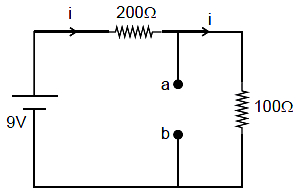
0 likes
View SolutionSemiconductor Electronics — Zener Diode · Frequently Asked Questions
1Are these Semiconductor Electronics questions useful for JEE and NEET?
Yes. All questions in this section are mapped to JEE Main and NEET exam patterns. Previous year questions from JEE Main, NEET, GUJCET and state-level exams are included with full solutions.
2Can I switch to Hindi or Gujarati for these questions?
Yes. Use the language tabs in the hero section or the sidebar to view the same questions and solutions in English, Hindi or Gujarati.
3How do I generate a question paper from this subtopic?
Use the Vedclass Exam Paper Generator — select the chapter and subtopic, set difficulty, and generate Sets A, B, C, D automatically. First 3 chapters of every subject are free.
Vedclass Products
For Students
Vedclass Test Series
Mock tests in real JEE/NEET style with performance analysis. 5-day free trial.
Start Free TrialFor Teachers
Exam Paper Generator
Generate Set A/B/C/D papers from this chapter in 2 minutes. 3 chapters free.
Try FreeFor Institutes
Online Exam Module
Live online exams with unlimited students, 360° analytics & white-label branding.
See DemoFor Teachers & Institutes
Generate a Semiconductor Electronics Exam Paper in 2 Minutes
Select subtopic & difficulty — Sets A, B, C, D auto-generated with No Repeat logic.
First 3 chapters of every subject are free — no payment required.