
A English
Zener Diode Questions in English
Class 12 Physics · Semiconductor Electronics · Zener Diode
108+
Questions
English
Language
100%
With Solutions
Showing 8 of 108 questions in English
101
EasyMCQ
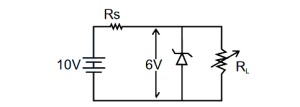
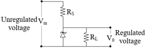
$A$ Zener diode having breakdown voltage $V_z = 6 \, V$ is used in a voltage regulator circuit as shown in the figure. The minimum current required to pass through the Zener to act as a voltage regulator is $10 \, mA$ and the maximum allowed current through the Zener is $40 \, mA$. The maximum value of $R_s$ for the Zener to act as a voltage regulator is (in $\Omega$)
A
$100$
B
$400$
C
$0.4$
D
$950$
Solution
(B) The voltage across the series resistor $R_s$ is given by $V_{R_s} = V_{in} - V_z = 10 \, V - 6 \, V = 4 \, V$.
For the Zener diode to act as a voltage regulator, it must maintain a minimum current $I_{z,min} = 10 \, mA$ even when the load current $I_L$ is zero.
The total current $I$ flowing through $R_s$ is $I = I_z + I_L$.
To find the maximum value of $R_s$, we consider the condition where the load current $I_L$ is minimum (i.e., $I_L = 0$).
Thus, $I = I_{z,min} = 10 \, mA$.
Using Ohm's law, $R_s = \frac{V_{R_s}}{I} = \frac{4 \, V}{10 \, mA} = \frac{4 \, V}{10 \times 10^{-3} \, A} = 400 \, \Omega$.
Therefore, the maximum value of $R_s$ is $400 \, \Omega$.
0 likes
View Solution102
EasyMCQ
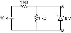
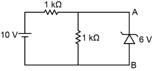
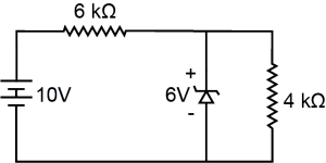
In the circuit shown, what will be the current through the $6 V$ zener diode?
A
$6 mA$, from $A$ to $B$
B
$2 mA$, from $A$ to $B$
C
$2 mA$, from $B$ to $A$
D
Zero
Solution
(D) To determine if the Zener diode is in breakdown, we first calculate the voltage across the parallel combination of the $1 k\Omega$ resistor and the Zener diode without the Zener diode connected.
Using the voltage divider rule, the voltage $V_{AB}$ across the $1 k\Omega$ resistor is:
$V_{AB} = V_s \times \frac{R_{parallel}}{R_s + R_{parallel}} = 10 V \times \frac{1 k\Omega}{1 k\Omega + 1 k\Omega} = 10 V \times \frac{1}{2} = 5 V$.
Since the voltage across the terminals $A$ and $B$ is $5 V$, which is less than the Zener breakdown voltage of $6 V$, the Zener diode does not conduct.
Therefore, the current through the Zener diode is $0 A$ (Zero).
0 likes
View Solution103
EasyMCQ
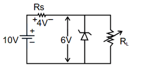
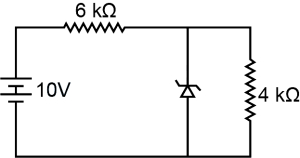
What will be the current flowing through the $6 \text{ k}\Omega$ resistor in the circuit shown,where the breakdown voltage of the Zener diode is $6 \text{ V}$?
A
$\frac{2}{3} \text{ mA}$
B
$1 \text{ mA}$
C
$10 \text{ mA}$
D
$\frac{3}{2} \text{ mA}$
Solution
(A) In the given circuit,the Zener diode is connected in parallel with the $4 \text{ k}\Omega$ resistor. Since the Zener diode is operating in its breakdown region,the voltage across it is constant at $6 \text{ V}$.
Because the Zener diode and the $4 \text{ k}\Omega$ resistor are in parallel,the voltage across the $4 \text{ k}\Omega$ resistor is also $6 \text{ V}$.
The total voltage in the circuit is $10 \text{ V}$. The voltage drop across the $6 \text{ k}\Omega$ series resistor is the difference between the source voltage and the Zener breakdown voltage:
$V_{6\text{k}\Omega} = 10 \text{ V} - 6 \text{ V} = 4 \text{ V}$.
The current flowing through the $6 \text{ k}\Omega$ resistor is given by Ohm's law:
$I = \frac{V_{6\text{k}\Omega}}{R} = \frac{4 \text{ V}}{6 \text{ k}\Omega} = \frac{4}{6} \text{ mA} = \frac{2}{3} \text{ mA}$.
0 likes
View Solution104
MediumMCQ
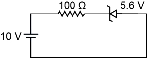
$A$ Zener diode having a breakdown voltage of $5.6 \ V$ is connected in reverse bias with a battery of emf $10 \ V$ and a resistance of $100 \ \Omega$ in series. The current flowing through the Zener diode is (in $mA$)
A
$88$
B
$0.88$
C
$4.4$
D
$44$
Solution
(D) The Zener diode is connected in series with a resistor $R = 100 \ \Omega$ and a battery of emf $V = 10 \ V$.
When the Zener diode is in the breakdown region,it maintains a constant voltage across it equal to its breakdown voltage,$V_Z = 5.6 \ V$.
The potential difference across the resistor $R$ is given by $\Delta V = V - V_Z = 10 \ V - 5.6 \ V = 4.4 \ V$.
Using Ohm's law,the current $I$ flowing through the circuit (and thus through the Zener diode) is:
$I = \frac{\Delta V}{R} = \frac{4.4 \ V}{100 \ \Omega} = 0.044 \ A$.
Converting this to milliamperes:
$I = 0.044 \times 1000 \ mA = 44 \ mA$.
0 likes
View Solution105
MediumMCQ
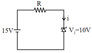
$A$ voltage regulating circuit consisting of a Zener diode,having a breakdown voltage of $10 \ V$ and a maximum power dissipation of $0.4 \ W$,is operated at $15 \ V$. The approximate value of the protective resistance in this circuit is . . . . . . $\Omega$.
A
$100$
B
$150$
C
$125$
D
$200$
Solution
(C) The Zener diode is used for voltage regulation. The power dissipation $P_D$ of the Zener diode is given by $P_D = V_Z \times i$,where $V_Z$ is the breakdown voltage and $i$ is the current through the diode.
Given $P_D = 0.4 \ W$ and $V_Z = 10 \ V$,we have:
$0.4 = 10 \times i$
$i = \frac{0.4}{10} = 0.04 \ A$
The protective resistance $R$ is connected in series with the Zener diode. The voltage drop across the resistance $R$ is $V_R = V_{source} - V_Z = 15 \ V - 10 \ V = 5 \ V$.
Using Ohm's law,$V_R = i \times R$,we get:
$R = \frac{V_R}{i} = \frac{5 \ V}{0.04 \ A} = 125 \ \Omega$.
0 likes
View Solution106
DifficultMCQ
The following diagram shows a Zener diode as a voltage regulator. The Zener diode is rated at $V_Z = 5 \text{ V}$ and the desired current in the load is $5 \text{ mA}$. The unregulated voltage source can supply up to $25 \text{ V}$. Considering the Zener diode can withstand four times the load current,the value of resistor $R_S$ (shown in the circuit) should be . . . . . . $\Omega$. (in $\text{ } \Omega$)
A
$4000$
B
$10$
C
$100$
D
$800$
Solution
(D) Given: Zener voltage $V_Z = 5 \text{ V}$,load current $I_L = 5 \text{ mA}$.
Maximum Zener current $I_Z = 4 \times I_L = 4 \times 5 \text{ mA} = 20 \text{ mA}$.
Total current through the series resistor $R_S$ is $I = I_L + I_Z = 5 \text{ mA} + 20 \text{ mA} = 25 \text{ mA} = 25 \times 10^{-3} \text{ A}$.
Maximum input voltage $V_{\text{in}} = 25 \text{ V}$.
The voltage drop across the series resistor $R_S$ is $V_{R_S} = V_{\text{in}} - V_Z = 25 \text{ V} - 5 \text{ V} = 20 \text{ V}$.
Using Ohm's law,$R_S = \frac{V_{R_S}}{I} = \frac{20 \text{ V}}{25 \times 10^{-3} \text{ A}} = 800 \Omega$.
0 likes
View Solution107
DifficultMCQ
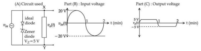
For the given circuit (shown in part $(A)$),the time-dependent input voltage $v_{in}(t)$ and the corresponding output voltage $v_{o}(t)$ are shown in part $(B)$ and part $(C)$,respectively. Identify the components that are used in the circuit between points $X$ and $Y$.
A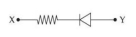
B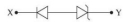
C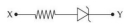
D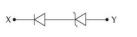
Solution
(B) The circuit in $(A)$ consists of an ideal diode and a Zener diode connected in series,which acts as a voltage clipper.
From part $(C)$,the output voltage $v_{o}(t)$ is clipped at $+5 \text{ V}$ and $-5 \text{ V}$ (since the Zener breakdown voltage $V_Z = 5 \text{ V}$).
The input voltage $v_{in}(t)$ (part $B$) is a sine wave with an amplitude of $20 \text{ V}$.
When the input is positive,the Zener diode operates in the breakdown region,clamping the output to $+5 \text{ V}$.
When the input is negative,the ideal diode is forward-biased and the Zener diode is reverse-biased,clamping the output to $-5 \text{ V}$.
Thus,the circuit between points $X$ and $Y$ consists of an ideal diode and a Zener diode connected in series. Among the given options,the configuration that represents this behavior is the series combination of two diodes (one ideal and one Zener,though the diagram in option $B$ shows two standard diodes,the question implies identifying the series combination of the two components shown in the circuit). However,based on the standard interpretation of such problems,the correct arrangement is the series connection of the two diodes.
0 likes
View Solution108
DifficultMCQ
$A$ diode has Zener voltage of $10 \text{ V}$ and maximum power dissipation of $0.5 \text{ W}$. The minimum resistance to be used in series with this diode for safety when it is connected to a $25 \text{ V}$ power supply is . . . . . . $\Omega$.
A
$300$
B
$400$
C
$500$
D
$600$
Solution
(A) The maximum current $I_{max}$ that the Zener diode can handle is given by $P = V_z I_{max}$.
Therefore,$I_{max} = \frac{P}{V_z} = \frac{0.5 \text{ W}}{10 \text{ V}} = 0.05 \text{ A}$.
The voltage across the series resistor $R$ is $V_R = V_{supply} - V_z = 25 \text{ V} - 10 \text{ V} = 15 \text{ V}$.
For safety,the minimum resistance $R_{min}$ is calculated using Ohm's law: $R_{min} = \frac{V_R}{I_{max}} = \frac{15 \text{ V}}{0.05 \text{ A}} = 300 \text{ } \Omega$.
0 likes
View SolutionSemiconductor Electronics — Zener Diode · Frequently Asked Questions
1Are these Semiconductor Electronics questions useful for JEE and NEET?
Yes. All questions in this section are mapped to JEE Main and NEET exam patterns. Previous year questions from JEE Main, NEET, GUJCET and state-level exams are included with full solutions.
2Can I switch to Hindi or Gujarati for these questions?
Yes. Use the language tabs in the hero section or the sidebar to view the same questions and solutions in English, Hindi or Gujarati.
3How do I generate a question paper from this subtopic?
Use the Vedclass Exam Paper Generator — select the chapter and subtopic, set difficulty, and generate Sets A, B, C, D automatically. First 3 chapters of every subject are free.
Vedclass Products
For Students
Vedclass Test Series
Mock tests in real JEE/NEET style with performance analysis. 5-day free trial.
Start Free TrialFor Teachers
Exam Paper Generator
Generate Set A/B/C/D papers from this chapter in 2 minutes. 3 chapters free.
Try FreeFor Institutes
Online Exam Module
Live online exams with unlimited students, 360° analytics & white-label branding.
See DemoFor Teachers & Institutes
Generate a Semiconductor Electronics Exam Paper in 2 Minutes
Select subtopic & difficulty — Sets A, B, C, D auto-generated with No Repeat logic.
First 3 chapters of every subject are free — no payment required.