
A English
R-L D.C. Circuit Questions in English
Class 12 Physics · Electromagnetic Induction · R-L D.C. Circuit
135+
Questions
English
Language
100%
With Solutions
Showing 50 of 135 questions in English
51
MediumMCQ
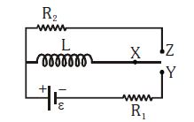
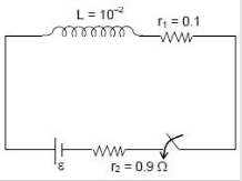
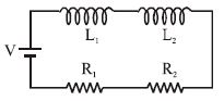
In the circuit shown,$X$ is joined to $Y$ for a long time,and then $X$ is joined to $Z$. The total heat produced in $R_2$ is
A
$\frac{L\varepsilon^2}{2R_1^2}$
B
$\frac{L\varepsilon^2}{2R_2^2}$
C
$\frac{L\varepsilon^2}{2R_1R_2}$
D
$\frac{L\varepsilon^2R_2}{2R_1^3}$
Solution
(A) When $X$ is joined to $Y$ for a long time,the inductor $L$ acts as a short circuit in the steady state.
The steady-state current flowing through the inductor is $i_0 = \frac{\varepsilon}{R_1}$.
The energy stored in the magnetic field of the inductor is $U = \frac{1}{2}Li_0^2 = \frac{1}{2}L\left(\frac{\varepsilon}{R_1}\right)^2 = \frac{L\varepsilon^2}{2R_1^2}$.
When $X$ is joined to $Z$,the battery is disconnected and the inductor discharges through the resistor $R_2$.
Since the entire energy stored in the inductor is dissipated as heat in the circuit during the discharge process,the total heat produced in $R_2$ is equal to the initial stored energy $U = \frac{L\varepsilon^2}{2R_1^2}$.
0 likes
View Solution52
DifficultMCQ
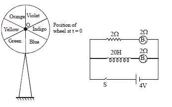
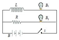
The figure shows $2$ identical bulbs $B_1$ and $B_2$ and a spinning wheel game divided into $6$ equal parts of different colors as shown. At $t = 0$,switch $S$ is closed and simultaneously the wheel is set to rotate about its center $O$ in a clockwise direction with an initial angular velocity of $2.5\pi \text{ rad/s}$. Find the color on which a student should place a bet if the color appearing on the pointer at the instant when both bulbs give the same illumination is selected for winning. Given: angular retardation of the wheel due to friction and other effects is $2\text{ rad/s}^2$ and take $\ln 2 = 0.7$.
A
Yellow
B
Blue
C
Green
D
Indigo
Solution
(C) The current in bulb $B_1$ is $I_1 = V/R = 4\text{V} / 2\Omega = 2\text{A}$.
The current in the circuit containing bulb $B_2$ and inductor $L$ is given by $I_2(t) = I_{max}(1 - e^{-t/\tau})$,where $I_{max} = 4\text{V} / 2\Omega = 2\text{A}$ and $\tau = L/R = 20\text{H} / 2\Omega = 10\text{s}$.
For the same illumination,the current in both bulbs must be the same. Since $B_1$ is purely resistive,its current is constant at $2\text{A}$. However,the problem implies the bulbs have the same illumination when the transient current in $B_2$ reaches the steady-state value of $B_1$. Re-evaluating: $I_1 = 2\text{A}$. For $I_2(t) = I_1$,we need $2(1 - e^{-t/10}) = 2$,which is impossible. Looking at the circuit,$B_1$ is in a branch with $2\Omega$ resistance. $B_2$ is in a branch with $2\Omega$ resistance and $20\text{H}$ inductor. The steady state current in both is $2\text{A}$. The question likely implies the time constant $\tau = L/R = 20/2 = 10\text{s}$. If the illumination is same at $I_2 = 1\text{A}$,then $1 = 2(1 - e^{-t/10}) \Rightarrow 0.5 = 1 - e^{-t/10} \Rightarrow e^{-t/10} = 0.5 \Rightarrow t = 10 \ln 2 = 7\text{s}$.
Angle rotated by the wheel: $\theta = \omega_i t - \frac{1}{2} \alpha t^2 = (2.5\pi)(7) - \frac{1}{2}(2)(7)^2 = 17.5\pi - 49 \text{ rad}$.
$17.5\pi \approx 54.978$. $\theta = 54.978 - 49 = 5.978 \text{ rad}$.
$5.978 \text{ rad} \times (180/\pi) \approx 342.5^{\circ}$.
Since the wheel starts at the vertical pointer (between Violet and Indigo),$342.5^{\circ}$ clockwise rotation places the pointer in the Green sector.
0 likes
View Solution53
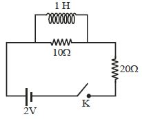
DifficultMCQ
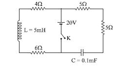
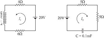
In the circuit shown,the key $(K)$ is closed at $t = 0$. Find the current through the key at the instant $t = 10^{-3} \ln 2 \, s$.
A
$1.5 \, A$
B
$2.5 \, A$
C
$4 \, A$
D
$2/3 \, A$
Solution
(B) The circuit can be analyzed by splitting it into two independent loops connected to the battery.
Loop $1$ (Left loop): Contains the battery $(20 \, V)$,inductor $(L = 5 \, mH)$,and resistors ($4 \, \Omega$ and $6 \, \Omega$). The total resistance is $R_1 = 4 + 6 = 10 \, \Omega$. The time constant is $\tau_1 = L/R_1 = 5 \times 10^{-3} / 10 = 5 \times 10^{-4} \, s$. The current $I_1(t) = \frac{V}{R_1} (1 - e^{-t/\tau_1}) = \frac{20}{10} (1 - e^{-t / (5 \times 10^{-4})}) = 2 (1 - e^{-2000t})$.
Loop $2$ (Right loop): Contains the battery $(20 \, V)$,capacitor $(C = 0.1 \, mF = 10^{-4} \, F)$,and resistors ($5 \, \Omega$ and $5 \, \Omega$). The total resistance is $R_2 = 5 + 5 = 10 \, \Omega$. The time constant is $\tau_2 = R_2 C = 10 \times 10^{-4} = 10^{-3} \, s$. The current $I_2(t) = \frac{V}{R_2} e^{-t/\tau_2} = \frac{20}{10} e^{-t/10^{-3}} = 2 e^{-1000t}$.
At $t = 10^{-3} \ln 2 \, s$:
$I_1 = 2 (1 - e^{-2000 \times 10^{-3} \ln 2}) = 2 (1 - e^{-2 \ln 2}) = 2 (1 - e^{\ln(2^{-2})}) = 2 (1 - 1/4) = 2(3/4) = 1.5 \, A$.
$I_2 = 2 e^{-1000 \times 10^{-3} \ln 2} = 2 e^{-\ln 2} = 2 (1/2) = 1 \, A$.
The total current through the key $K$ is $I = I_1 + I_2 = 1.5 + 1 = 2.5 \, A$.
0 likes
View Solution54
MediumMCQ
In the given $L-R$ circuit,which of the following statements is correct?
A
The magnitude of the rate of change of current is $\frac{\varepsilon}{2L}$ when the energy stored in the inductor is $\frac{L\varepsilon^2}{8R^2}$.
B
The magnitude of the rate of change of current is $\frac{\varepsilon}{L}$ when the energy stored in the inductor is $\frac{L\varepsilon^2}{4R^2}$.
C
The magnitude of the rate of change of current is $\frac{\varepsilon}{2L}$ when the energy stored in the inductor is $\frac{L\varepsilon^2}{4R^2}$.
D
All the options may be correct.
Solution
(A) For an $L-R$ circuit connected to a $DC$ source $\varepsilon$,the Kirchhoff's voltage law equation is $\varepsilon = L \frac{dI}{dt} + IR$.
The energy stored in the inductor is given by $U = \frac{1}{2} LI^2$.
For option $A$,the energy is $U = \frac{L\varepsilon^2}{8R^2}$.
Equating this to $\frac{1}{2} LI^2$,we get $\frac{1}{2} LI^2 = \frac{L\varepsilon^2}{8R^2}$,which simplifies to $I^2 = \frac{\varepsilon^2}{4R^2}$,so $I = \frac{\varepsilon}{2R}$.
Substituting $I$ into the circuit equation: $\varepsilon = L \frac{dI}{dt} + (\frac{\varepsilon}{2R})R = L \frac{dI}{dt} + \frac{\varepsilon}{2}$.
This gives $L \frac{dI}{dt} = \frac{\varepsilon}{2}$,or $\frac{dI}{dt} = \frac{\varepsilon}{2L}$.
Thus,option $A$ is correct.
0 likes
View Solution55
MediumMCQ
Calculate the current,a long time after the closing of the key $K$ in a circuit containing a battery of $10 \ V$,a resistor of $2 \ \Omega$,and an inductor of $5 \ H$. (in $A$)
A
$2.5$
B
$5$
C
$7$
D
$3$
Solution
(B) When the key $K$ is closed,the inductor opposes the change in current. However,after a long time,the current reaches a steady state.
In the steady state,the inductor acts as a simple wire with zero resistance (ideal inductor).
The circuit behaves as a simple $DC$ circuit with only the battery and the resistor.
Using Ohm's Law: $I = \frac{V}{R}$.
Given $V = 10 \ V$ and $R = 2 \ \Omega$.
Therefore,$I = \frac{10}{2} = 5 \ A$.
In the steady state,the inductor acts as a simple wire with zero resistance (ideal inductor).
The circuit behaves as a simple $DC$ circuit with only the battery and the resistor.
Using Ohm's Law: $I = \frac{V}{R}$.
Given $V = 10 \ V$ and $R = 2 \ \Omega$.
Therefore,$I = \frac{10}{2} = 5 \ A$.
0 likes
View Solution56
EasyMCQ
An inductor with an iron core is connected in series with a resistor $R$ across an ideal $DC$ source. The circuit is in a steady state. If the iron core is removed, what happens to the current flowing through the inductor immediately after the removal of the core?
A
Increases
B
Decreases
C
Remains unchanged
D
First increases then decreases
Solution
(A) In an inductor, the magnetic flux $\phi = LI$ cannot change instantaneously.
Initially, the inductor has an iron core, so its inductance is $L_1 = L_{core}$. The steady-state current is $I_1 = V/R$.
The magnetic flux linked with the inductor is $\phi_1 = L_1 I_1$.
When the iron core is removed, the inductance changes to $L_2$ (where $L_2 < L_1$).
Since the flux cannot change instantaneously, the current $I_2$ immediately after removal must satisfy $\phi_1 = \phi_2$, which means $L_1 I_1 = L_2 I_2$.
Since $L_2 < L_1$, it follows that $I_2 = (L_1/L_2) I_1 > I_1$.
Therefore, the current flowing through the inductor increases immediately after the removal of the iron core.
0 likes
View Solution57
MediumMCQ
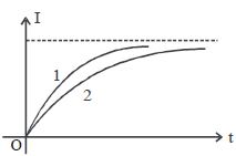
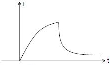
When a certain circuit consisting of an emf $E$,an inductance $L$,and a resistance $R$ is closed,the current in it increases with time according to curve $1$. After one parameter ($L$ or $R$) is changed,the increase in the current follows curve $2$,when the circuit is closed a second time. Which parameter was changed?
A
$L$ is increased
B
$L$ is decreased
C
$R$ is increased
D
$R$ is decreased
Solution
(A) The current in an $LR$ circuit at time $t$ is given by $I(t) = \frac{E}{R}(1 - e^{-Rt/L})$.
As $t \to \infty$,the steady-state current is $I_{max} = \frac{E}{R}$.
From the graph,both curves approach the same steady-state current value,which implies that the resistance $R$ remains unchanged.
The time constant of the circuit is $\tau = \frac{L}{R}$.
Curve $2$ reaches the steady-state value more slowly than curve $1$,which means the time constant for curve $2$ is larger than that for curve $1$ $(\tau_2 > \tau_1)$.
Since $\tau = \frac{L}{R}$ and $R$ is constant,an increase in the time constant $\tau$ implies that the inductance $L$ must have been increased.
0 likes
View Solution58
DifficultMCQ
The time constant of an $LR$ circuit is $10 \, s$. When a resistance of $10 \, \Omega$ is connected in series with the existing circuit,the time constant becomes $2 \, s$. The self-inductance of the circuit is ..... $H$.
A
$2.5$
B
$5$
C
$15$
D
$25$
Solution
(D) The time constant $\tau$ of an $LR$ circuit is given by $\tau = \frac{L}{R}$.
Initially,$\frac{L}{R} = 10$,which implies $L = 10R$ --- $(1)$.
When a resistance of $10 \, \Omega$ is added in series,the new resistance becomes $(R + 10) \, \Omega$. The new time constant is $\frac{L}{R + 10} = 2$,which implies $L = 2(R + 10) = 2R + 20$ --- $(2)$.
Equating $(1)$ and $(2)$:
$10R = 2R + 20$
$8R = 20$
$R = 2.5 \, \Omega$.
Substituting $R$ into equation $(1)$:
$L = 10 \times 2.5 = 25 \, H$.
0 likes
View Solution59
DifficultMCQ
The current in an $LR$ circuit builds up to $3/4$ of its steady state value in $4 \, s$. The time constant of this circuit is:
A
$\frac{1}{\ln 2} \, s$
B
$\frac{2}{\ln 2} \, s$
C
$\frac{3}{\ln 2} \, s$
D
$\frac{4}{\ln 2} \, s$
Solution
(B) The growth of current in an $LR$ circuit is given by the formula: $I = I_0(1 - e^{-t/\tau})$,where $\tau$ is the time constant.
Given that at $t = 4 \, s$,$I = \frac{3}{4} I_0$.
Substituting these values into the equation:
$\frac{3}{4} I_0 = I_0(1 - e^{-4/\tau})$
$\frac{3}{4} = 1 - e^{-4/\tau}$
$e^{-4/\tau} = 1 - \frac{3}{4} = \frac{1}{4}$
Taking the natural logarithm on both sides:
$-\frac{4}{\tau} = \ln(\frac{1}{4})$
$-\frac{4}{\tau} = -\ln(4) = -\ln(2^2) = -2 \ln 2$
$\tau = \frac{4}{2 \ln 2} = \frac{2}{\ln 2} \, s$.
0 likes
View Solution60
DifficultMCQ
Find the time constant of the following circuit.
A
$\frac{3}{2}\frac{L}{R}$
B
$\frac{3}{2}\frac{R}{L}$
C
$\frac{2}{3}\frac{L}{R}$
D
$\frac{2}{3}\frac{R}{L}$
Solution
(C) To find the time constant $\tau$ of an $LR$ circuit,we need to determine the equivalent resistance $R_{eq}$ as seen from the terminals of the inductor $L$ by short-circuiting the voltage source $E$.
$1$. Short-circuit the voltage source $E$. The circuit now consists of two resistors $R$ in parallel with each other,and this combination is in series with the third resistor $R$.
$2$. The two resistors $R$ connected in parallel have an equivalent resistance of $R_p = \frac{R \times R}{R + R} = \frac{R}{2}$.
$3$. This parallel combination is in series with the remaining resistor $R$. Therefore,the total equivalent resistance $R_{eq}$ seen by the inductor is $R_{eq} = R + \frac{R}{2} = \frac{3}{2}R$.
$4$. The time constant $\tau$ for an $LR$ circuit is given by $\tau = \frac{L}{R_{eq}}$.
$5$. Substituting the value of $R_{eq}$,we get $\tau = \frac{L}{\frac{3}{2}R} = \frac{2L}{3R}$.
0 likes
View Solution61
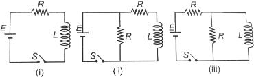
DifficultMCQ
In which of the following circuits is the current maximum just after the switch $S$ is closed?
A
$(i)$
B
$(ii)$
C
$(iii)$
D
Both $(ii)$ and $(iii)$
Solution
(D) At $t=0$,the inductor $L$ opposes any change in current,so it acts as an open circuit (current through it is zero).
For circuit $(i)$: The entire circuit is open,so the current $i_1 = 0$.
For circuit $(ii)$: The inductor $L$ is in series with resistor $R$. At $t=0$,the branch containing $L$ is open. The current flows through the parallel resistor $R$ connected directly to the source $E$. Thus,$i_2 = E/R$.
For circuit $(iii)$: The inductor $L$ is in parallel with resistor $R$. At $t=0$,the branch containing $L$ is open. The current flows through the resistor $R$ in parallel. Thus,$i_3 = E/R$.
Comparing the currents,$i_2 = i_3 = E/R$,which is greater than $i_1 = 0$. Therefore,the current is maximum in both circuits $(ii)$ and $(iii)$.
0 likes
View Solution62
DifficultMCQ
An inductor $(L = 100 \, mH)$,a resistor $(R = 100 \, \Omega)$ and a battery $(E = 100 \, V)$ are initially connected in series as shown in the figure. After a long time,the battery is disconnected by short-circuiting the points $A$ and $B$. The current in the circuit $1 \, ms$ after the short circuit is
A
$1/e \, A$
B
$e \, A$
C
$0.1 \, A$
D
$1 \, A$
Solution
(A) When the circuit is connected for a long time,the inductor acts as a short circuit,and the steady-state current $I_0$ is given by:
$I_0 = \frac{E}{R} = \frac{100 \, V}{100 \, \Omega} = 1 \, A$
When the battery is disconnected and points $A$ and $B$ are short-circuited,the circuit becomes a decaying $LR$ circuit. The current at time $t$ is given by:
$I(t) = I_0 e^{-t/\tau}$
Here,the time constant $\tau$ is:
$\tau = \frac{L}{R} = \frac{100 \times 10^{-3} \, H}{100 \, \Omega} = 1 \times 10^{-3} \, s = 1 \, ms$
Given $t = 1 \, ms$,the current is:
$I = 1 \times e^{-1 \, ms / 1 \, ms} = 1 \times e^{-1} = \frac{1}{e} \, A$
0 likes
View Solution63
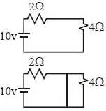
MediumMCQ
The current in the $2\, \Omega$ resistance shown in the figure is:
$(a)$ Just after the closing of the key.
$(b)$ $A$ long time after the closing of the key.
$(a)$ Just after the closing of the key.
$(b)$ $A$ long time after the closing of the key.
A
$5\, A, \frac{5}{3}\, A$
B
$\frac{10}{6}\, A, 0$
C
$\frac{5}{3}\, A, 5\, A$
D
$0, 5\, A$
Solution
(C) At $t = 0$, the inductor acts as an open circuit because it opposes any sudden change in current. The circuit consists of the $10\, V$ battery, $2\, \Omega$ resistor, and $4\, \Omega$ resistor in series.
Total resistance $R_{eq} = 2\, \Omega + 4\, \Omega = 6\, \Omega$.
The current $I = \frac{V}{R_{eq}} = \frac{10\, V}{6\, \Omega} = \frac{5}{3}\, A$.
At $t = \infty$, the inductor acts as a short circuit (a wire with zero resistance) because the current has reached a steady state. The $4\, \Omega$ resistor is bypassed by the short-circuited inductor.
The circuit now consists of only the $10\, V$ battery and the $2\, \Omega$ resistor.
The current $I = \frac{10\, V}{2\, \Omega} = 5\, A$.
Thus, the currents are $\frac{5}{3}\, A$ and $5\, A$ respectively.
0 likes
View Solution64
MediumMCQ
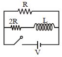
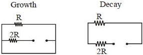
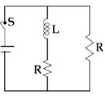
The ratio of time constants during growth and decay of current in the circuit is
A
$1 : 1$
B
$3 : 2$
C
$2 : 3$
D
$1 : 3$
Solution
(B) For the growth of current,the switch is closed. The inductor $L$ is in series with the resistor $2R$. The resistor $R$ is in parallel with the series combination of $2R$ and $L$. The equivalent resistance $R_{eq}$ seen by the inductor during growth is $2R$ (since the battery acts as a short circuit for the ideal case or is considered part of the loop). Thus,the time constant for growth is $\tau_{growth} = \frac{L}{2R}$.
For the decay of current,the switch is opened. The inductor $L$ now forms a closed loop with the resistors $R$ and $2R$ in series. The equivalent resistance $R_{eq}$ seen by the inductor during decay is $R + 2R = 3R$. Thus,the time constant for decay is $\tau_{decay} = \frac{L}{3R}$.
The ratio of time constants during growth and decay is $\frac{\tau_{growth}}{\tau_{decay}} = \frac{L/2R}{L/3R} = \frac{3R}{2R} = \frac{3}{2}$ or $3 : 2$.
0 likes
View Solution65
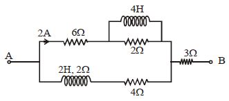
MediumMCQ
Find $V_A - V_B$ in steady state. (in $, V$)
A
$8$
B
$16$
C
$24$
D
$28$
Solution
(C) In steady state,the inductor acts as a short circuit (zero resistance).
The upper branch has a $6 \, \Omega$ resistor in series with a parallel combination of a $4 \, H$ inductor and a $2 \, \Omega$ resistor. Since the inductor is a short circuit,the $2 \, \Omega$ resistor is bypassed. Thus,the resistance of the upper branch is $6 \, \Omega$.
The lower branch has a $2 \, H$ inductor in series with a $2 \, \Omega$ resistor and a $4 \, \Omega$ resistor. The inductor acts as a short circuit,so the resistance of the lower branch is $2 \, \Omega + 4 \, \Omega = 6 \, \Omega$.
The total current entering the parallel combination is $2 \, A$ in the upper branch. Since both branches have equal resistance $(6 \, \Omega)$,the current in the lower branch is also $2 \, A$.
The total current flowing through the $3 \, \Omega$ resistor is $I_{total} = 2 \, A + 2 \, A = 4 \, A$.
The potential difference $V_A - V_B$ is the sum of the potential drop across the upper branch and the $3 \, \Omega$ resistor: $V_A - V_B = (I_{upper} \times R_{upper}) + (I_{total} \times R_{series}) = (2 \, A \times 6 \, \Omega) + (4 \, A \times 3 \, \Omega) = 12 \, V + 12 \, V = 24 \, V$.
0 likes
View Solution66
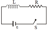
DifficultMCQ
An inductor $(L)$ - resistance $(R)$ battery circuit is switched on at $t = 0$. If the $e.m.f.$ of the battery is $E$,what is the charge passing through the battery in time constant $T$?
A
$\frac{ET}{eR}$
B
$\frac{eET}{R}$
C
$\frac{ET}{R \pi e}$
D
$\frac{2ET}{eR}$
Solution
(A) The current in an $LR$ circuit at time $t$ is given by $I(t) = \frac{E}{R}(1 - e^{-t/T})$,where $T = L/R$ is the time constant.
The charge $q$ passing through the battery in time $T$ is the integral of current with respect to time:
$q = \int_{0}^{T} I(t) dt = \int_{0}^{T} \frac{E}{R}(1 - e^{-t/T}) dt$
Integrating the expression:
$q = \frac{E}{R} \left[ t - (-T)e^{-t/T} \right]_{0}^{T}$
$q = \frac{E}{R} \left[ t + Te^{-t/T} \right]_{0}^{T}$
Substituting the limits:
$q = \frac{E}{R} \left[ (T + Te^{-T/T}) - (0 + Te^{0}) \right]$
$q = \frac{E}{R} \left[ T + \frac{T}{e} - T \right]$
$q = \frac{ET}{eR}$
0 likes
View Solution67
MediumMCQ
An inductor coil carries a steady-state current of $2.0 \ A$ when connected across an ideal battery of $emf$ $4.0 \ V$. If its inductance is $1.0 \ H$,find the time constant of the circuit in $sec$.
A
$0.5$
B
$0.2$
C
$1$
D
$2$
Solution
(A) In a steady-state condition,an inductor acts as a short circuit (ideal wire) because the current is constant $(di/dt = 0)$.
Given: Steady-state current $I = 2.0 \ A$,$emf$ $E = 4.0 \ V$,and inductance $L = 1.0 \ H$.
Using Ohm's law for the steady state: $R = E / I = 4.0 / 2.0 = 2.0 \ \Omega$.
The time constant $\tau$ of an $LR$ circuit is given by the formula: $\tau = L / R$.
Substituting the values: $\tau = 1.0 \ H / 2.0 \ \Omega = 0.5 \ s$.
Therefore,the time constant of the circuit is $0.5 \ s$.
0 likes
View Solution68
DifficultMCQ
In the circuits $(a)$ and $(b)$,switches $S_1$ and $S_2$ are closed at $t = 0$ and are kept closed for a long time. The variations of current in the two circuits for $t \ge 0$ are roughly shown by which figure? (Figures are schematic and not drawn to scale.)
A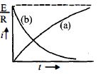
B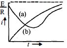
C
D
Solution
(D) In circuit $(a)$,we have an $RC$ series circuit. When the switch is closed at $t=0$,the capacitor starts charging. The current in the circuit is given by $i(t) = \frac{E}{R} e^{-t/RC}$. This shows that the current starts at a maximum value of $\frac{E}{R}$ and decays exponentially to zero as $t \to \infty$.
In circuit $(b)$,we have an $RL$ series circuit. When the switch is closed at $t=0$,the inductor opposes the change in current. The current in the circuit is given by $i(t) = \frac{E}{R} (1 - e^{-Rt/L})$. This shows that the current starts at $0$ and increases exponentially to a maximum steady-state value of $\frac{E}{R}$ as $t \to \infty$.
Comparing these behaviors with the given options,figure $(d)$ shows curve $(a)$ starting at $\frac{E}{R}$ and decaying,and curve $(b)$ starting at $0$ and increasing to $\frac{E}{R}$. Thus,figure $(d)$ is the correct representation.
0 likes
View Solution69
MediumMCQ
In the circuit shown,the switch $S_1$ is closed at time $t = 0$ and the switch $S_2$ is kept open. At some later time $t_0$,the switch $S_1$ is opened and $S_2$ is closed. The behavior of the current $I$ as a function of time $t$ is given by:
A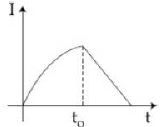
B
C
D
None of these
Solution
(A) For $0 \le t < t_0$,the circuit consists of a battery,resistor $R$,and inductor $L$ in series. The current grows exponentially as $I(t) = \frac{\epsilon}{R}(1 - e^{-Rt/L})$.
At $t = t_0$,the current reaches a value $I_0 = \frac{\epsilon}{R}(1 - e^{-Rt_0/L})$.
For $t \ge t_0$,the switch $S_1$ is opened and $S_2$ is closed. The battery is removed,and the inductor $L$ discharges through the resistor $R$. The current decays exponentially as $I(t) = I_0 e^{-R(t-t_0)/L}$.
The correct graph shows exponential growth followed by exponential decay to zero,which matches the provided solution image.
0 likes
View Solution70
MediumMCQ
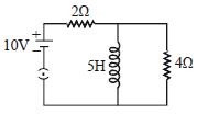
In the figure shown,a circuit contains two identical resistors with resistance $R = 5\,\Omega$ and an inductance with $L = 2\, mH$. An ideal battery of $15\, V$ is connected in the circuit. What will be the current through the battery long after the switch $S$ is closed (in $, A$)?
A
$5.5$
B
$7.5$
C
$3$
D
$6$
Solution
(D) After a long time,the inductor acts as a short circuit (a wire with zero resistance) because the current becomes steady.
The circuit now consists of two resistors of $5\,\Omega$ each,connected in parallel across the $15\, V$ battery.
The equivalent resistance $R_{eq}$ of the two parallel resistors is given by:
$R_{eq} = \frac{R \times R}{R + R} = \frac{5 \times 5}{5 + 5} = \frac{25}{10} = 2.5\,\Omega$
The current $i$ through the battery is given by Ohm's law:
$i = \frac{V}{R_{eq}} = \frac{15}{2.5} = 6\, A$
0 likes
View Solution71
DifficultMCQ
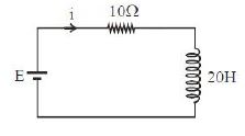
$A$ $20 \, H$ inductor coil is connected to a $10 \, \Omega$ resistance in series as shown in the figure. The time at which the rate of dissipation of energy (Joule's heat) across the resistance is equal to the rate at which magnetic energy is stored in the inductor is:
A
$\frac{2}{\ln 2} \, s$
B
$\ln 2 \, s$
C
$\frac{1}{2} \ln 2 \, s$
D
$2 \ln 2 \, s$
Solution
(D) The current in an $LR$ circuit at time $t$ is given by $I = I_0(1 - e^{-t/\tau})$,where $I_0 = E/R$ and $\tau = L/R$.
Given $L = 20 \, H$ and $R = 10 \, \Omega$,the time constant $\tau = 20/10 = 2 \, s$.
So,$I = \frac{E}{10}(1 - e^{-t/2})$.
The rate of dissipation of energy (Joule's heat) across the resistance is $P_R = I^2 R = I^2 \times 10$.
The rate at which magnetic energy is stored in the inductor is $P_L = \frac{d}{dt}(\frac{1}{2} L I^2) = L I \frac{dI}{dt}$.
Equating $P_R = P_L$,we get $I^2 R = L I \frac{dI}{dt}$,which simplifies to $I R = L \frac{dI}{dt}$.
Substituting $I = \frac{E}{10}(1 - e^{-t/2})$ and $\frac{dI}{dt} = \frac{E}{10} \times \frac{1}{2} e^{-t/2}$:
$\frac{E}{10}(1 - e^{-t/2}) \times 10 = 20 \times \frac{E}{20} e^{-t/2}$.
$1 - e^{-t/2} = e^{-t/2}$.
$1 = 2 e^{-t/2} \implies e^{-t/2} = 1/2$.
Taking the natural logarithm on both sides: $-t/2 = \ln(1/2) = -\ln 2$.
Therefore,$t = 2 \ln 2 \, s$.
0 likes
View Solution72
DifficultMCQ
$A$ coil of self-inductance $10\,mH$ and resistance $0.1\,\Omega$ is connected through a switch to a battery of internal resistance $0.9\,\Omega$. After the switch is closed,the time taken for the current to attain $80\%$ of its saturation value is: [take $ln\,5 = 1.6$] (in $,s$)
A
$0.016$
B
$0.324$
C
$0.002$
D
$0.103$
Solution
(A) Given: Self-inductance $L = 10\,mH = 10 \times 10^{-3}\,H$,coil resistance $r_1 = 0.1\,\Omega$,internal resistance $r_2 = 0.9\,\Omega$.
The total resistance of the circuit is $R = r_1 + r_2 = 0.1 + 0.9 = 1.0\,\Omega$.
The time constant of the $LR$ circuit is $\tau = \frac{L}{R} = \frac{10 \times 10^{-3}}{1.0} = 10^{-2}\,s$.
The current at any time $t$ is given by $i = i_0(1 - e^{-t/\tau})$,where $i_0$ is the saturation current.
We want to find $t$ when $i = 0.8 i_0$.
$0.8 i_0 = i_0(1 - e^{-t/\tau})$
$0.8 = 1 - e^{-t/\tau}$
$e^{-t/\tau} = 0.2 = \frac{1}{5}$
$e^{t/\tau} = 5$
Taking natural logarithm on both sides: $\frac{t}{\tau} = \ln 5$.
Given $\ln 5 = 1.6$,so $t = 1.6 \times \tau = 1.6 \times 10^{-2}\,s = 0.016\,s$.
0 likes
View Solution73
DifficultMCQ
Consider the $LR$ circuit shown in the figure. If the switch $S$ is closed at $t = 0$, then the amount of charge that passes through the battery between $t = 0$ and $t = \frac{L}{R}$ is
A
$\frac{EL}{7.3R^2}$
B
$\frac{EL}{2.7R^2}$
C
$\frac{7.3EL}{R^2}$
D
$\frac{2.7EL}{R^2}$
Solution
(B) The current in an $LR$ circuit as a function of time $t$ after closing the switch is given by
$i(t) = \frac{E}{R}\left(1 - e^{-\frac{Rt}{L}}\right)$.
The charge $q$ that passes through the battery in time interval $t = 0$ to $t = \frac{L}{R}$ is given by the integral of current with respect to time:
$q = \int_{0}^{\frac{L}{R}} i(t)\, dt = \int_{0}^{\frac{L}{R}} \frac{E}{R}\left(1 - e^{-\frac{Rt}{L}}\right) dt$
$q = \frac{E}{R} \int_{0}^{\frac{L}{R}} \left(1 - e^{-\frac{Rt}{L}}\right) dt$
$q = \frac{E}{R} \left[ t + \frac{L}{R} e^{-\frac{Rt}{L}} \right]_{0}^{\frac{L}{R}}$
$q = \frac{E}{R} \left[ \left(\frac{L}{R} + \frac{L}{R} e^{-1}\right) - \left(0 + \frac{L}{R} e^{0}\right) \right]$
$q = \frac{E}{R} \left[ \frac{L}{R} + \frac{L}{Re} - \frac{L}{R} \right]$
$q = \frac{E}{R} \cdot \frac{L}{Re} = \frac{EL}{eR^2}$
Since $e \approx 2.718$, we have:
$q = \frac{EL}{2.7R^2}$
0 likes
View Solution74
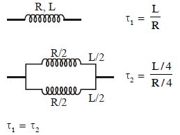
MediumMCQ
An inductance coil has a time constant of $4 \, sec$. If it is cut into two equal parts and connected in parallel,then the new time constant of the circuit is.....$sec$.
A
$4$
B
$2$
C
$1$
D
$0.5$
Solution
(A) The time constant of an $LR$ circuit is given by $\tau = \frac{L}{R}$.
Initially,$\tau_1 = \frac{L}{R} = 4 \, sec$.
When the coil is cut into two equal parts,the resistance and inductance of each part become half of the original values,i.e.,$R' = \frac{R}{2}$ and $L' = \frac{L}{2}$.
When these two parts are connected in parallel,the equivalent resistance $R_{eq}$ is given by $\frac{1}{R_{eq}} = \frac{1}{R'} + \frac{1}{R'} = \frac{2}{R'} = \frac{2}{R/2} = \frac{4}{R}$,so $R_{eq} = \frac{R}{4}$.
The equivalent inductance $L_{eq}$ for two inductors in parallel is $\frac{1}{L_{eq}} = \frac{1}{L'} + \frac{1}{L'} = \frac{2}{L'} = \frac{2}{L/2} = \frac{4}{L}$,so $L_{eq} = \frac{L}{4}$.
The new time constant is $\tau_2 = \frac{L_{eq}}{R_{eq}} = \frac{L/4}{R/4} = \frac{L}{R} = \tau_1$.
Therefore,the new time constant is $4 \, sec$.
0 likes
View Solution75
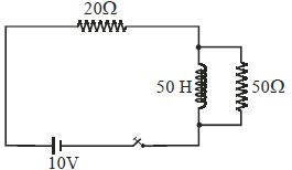
MediumMCQ
Two resistances $20\,\Omega$ and $50\,\Omega$ and a pure inductance of $50\,H$ are connected to a $10\,V$ battery through a key as shown in the figure. The key is closed at $t = 0$. Find the final value of current in the $50\,\Omega$ resistor.
A
$0$
B
$1/7$
C
$1/10$
D
$0.5$
Solution
(A) In a $DC$ circuit,after a long time $(t \to \infty)$,the inductor acts as a short circuit (a wire with zero resistance) because the current becomes steady and the induced $EMF$ across the inductor becomes zero.
Since the $50\,\Omega$ resistor is connected in parallel with the pure inductor,the entire current will flow through the path of least resistance,which is the inductor.
Therefore,the potential difference across the $50\,\Omega$ resistor becomes zero.
Consequently,the final current flowing through the $50\,\Omega$ resistor is $0\,A$.
0 likes
View Solution76
MediumMCQ
In the given circuit,the switch is in position $a$. For what value of $R$ will the circuit have a time constant of $10\,\mu s$ in $K\Omega$?
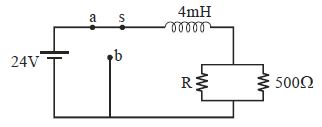
A
$2$
B
$2.5$
C
$1$
D
None of these
Solution
(A) The time constant $\tau$ for an $RL$ circuit is given by $\tau = \frac{L}{R_{eq}}$.
When the switch is in position $a$,the inductor $L = 4\,mH$ is in series with the parallel combination of resistors $R$ and $500\,\Omega$.
The equivalent resistance $R_{eq}$ is the resistance seen by the inductor,which is $R_{eq} = \frac{R \times 500}{R + 500}$.
Given $\tau = 10\,\mu s = 10 \times 10^{-6}\,s$ and $L = 4\,mH = 4 \times 10^{-3}\,H$.
Substituting these values into the formula:
$10 \times 10^{-6} = \frac{4 \times 10^{-3}}{\left(\frac{R \times 500}{R + 500}\right)}$
$10 \times 10^{-6} = \frac{4 \times 10^{-3} \times (R + 500)}{500R}$
$10^{-5} = \frac{4 \times 10^{-3} \times (R + 500)}{500R}$
$500R \times 10^{-5} = 4 \times 10^{-3} \times (R + 500)$
$5 \times 10^{-3} R = 4 \times 10^{-3} R + 2000 \times 10^{-3}$
$10^{-3} R = 2$
$R = 2000\,\Omega = 2\,K\Omega$.
0 likes
View Solution77
DifficultMCQ
$A$ solenoid has an inductance of $60\, H$ and a resistance of $30\, \Omega$. If it is connected to a $100\, V$ battery,how long will it take for the current to reach $\frac{e - 1}{e} \approx 63.2\%$ of its final value?
A
$1$
B
$2$
C
$e$
D
$2e$
Solution
(B) The current in an $LR$ circuit at time $t$ is given by the formula: $I(t) = I_0(1 - e^{-\frac{R}{L}t})$.
We are given that the current reaches $\frac{e-1}{e}$ of its final value $I_0$.
So,$I(t) = \left(\frac{e-1}{e}\right)I_0 = I_0(1 - e^{-1})$.
Comparing this with the formula,we get $e^{-\frac{R}{L}t} = e^{-1}$.
This implies $\frac{R}{L}t = 1$,or $t = \frac{L}{R}$.
Given $L = 60\, H$ and $R = 30\, \Omega$,we have $t = \frac{60}{30} = 2\, s$.
0 likes
View Solution78
MediumMCQ
An inductor coil stores $U$ energy when $I$ current is passed through it and dissipates energy at the rate of $P$. The time constant of the circuit,when this coil is connected across a battery of zero internal resistance,is
A
$\frac{4U}{P}$
B
$\frac{U}{P}$
C
$\frac{2U}{P}$
D
$\frac{2P}{U}$
Solution
(C) The energy stored in an inductor is given by $U = \frac{1}{2} L I^2$,where $L$ is the inductance and $I$ is the current.
From this,we can express the inductance as $L = \frac{2U}{I^2}$.
The rate of energy dissipation (power loss) in the inductor due to its internal resistance $R$ is given by $P = I^2 R$.
From this,we can express the resistance as $R = \frac{P}{I^2}$.
The time constant $\tau$ of an $LR$ circuit is defined as $\tau = \frac{L}{R}$.
Substituting the expressions for $L$ and $R$:
$\tau = \frac{2U / I^2}{P / I^2} = \frac{2U}{P}$.
Therefore,the time constant is $\frac{2U}{P}$.
0 likes
View Solution79
DifficultMCQ
The resistance in the following circuit is increased at a particular instant. At this instant,the value of resistance is $10\,\Omega$. The current in the circuit will be
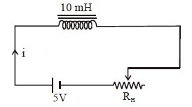
A
$i = 0.5\,A$
B
$i > 0.5\,A$
C
$i < 0.5\,A$
D
$i = 0$
Solution
(B) The circuit consists of a battery of $5\,V$,an inductor of $10\,mH$,and a variable resistor $R_H$.
According to Kirchhoff's voltage law,the equation for the circuit is $V = iR + L\frac{di}{dt}$.
If the resistance $R$ were constant at $10\,\Omega$,the steady-state current would be $i = \frac{V}{R} = \frac{5}{10} = 0.5\,A$.
However,the resistance is increasing,which means $\frac{dR}{dt} > 0$. As the resistance increases,the current $i$ tends to decrease.
According to Lenz's law,the inductor opposes this change by inducing an electromotive force $(EMF)$ that tries to maintain the current.
The induced $EMF$ is given by $\varepsilon = -L\frac{di}{dt}$. Since the current is decreasing,$\frac{di}{dt}$ is negative,making the induced $EMF$ positive in the direction of the main current.
This induced $EMF$ acts as a source that adds to the current,causing the actual current to be higher than the value it would have if the resistance were constant.
Therefore,$i > 0.5\,A$.
0 likes
View Solution80
DifficultMCQ
In a decaying $L-R$ circuit,the time after which energy stored in the inductor reduces to one-fourth of its initial value is
A
$(\ln 2) \frac{L}{R}$
B
$0.5 \frac{L}{R}$
C
$\sqrt{2} \frac{L}{R}$
D
$\left( \frac{\sqrt{2}}{\sqrt{2}-1} \right) \frac{L}{R}$
Solution
(A) The current in a decaying $L-R$ circuit is given by $i = i_0 e^{-t/\tau}$,where $\tau = L/R$ is the time constant.
The energy stored in the inductor is $U = \frac{1}{2} L i^2$.
Let $U_0$ be the initial energy,$U_0 = \frac{1}{2} L i_0^2$.
We are given that the energy reduces to one-fourth of its initial value,so $U = \frac{1}{4} U_0$.
Substituting the expressions for energy: $\frac{1}{2} L i^2 = \frac{1}{4} (\frac{1}{2} L i_0^2)$.
This simplifies to $i^2 = \frac{1}{4} i_0^2$,or $i = \frac{1}{2} i_0$.
Substituting $i = i_0 e^{-t/\tau}$,we get $i_0 e^{-t/\tau} = \frac{1}{2} i_0$.
$e^{-t/\tau} = \frac{1}{2} \Rightarrow e^{t/\tau} = 2$.
Taking the natural logarithm on both sides: $t/\tau = \ln 2$.
Therefore,$t = \tau \ln 2 = \frac{L}{R} \ln 2$.
0 likes
View Solution81
MediumMCQ
Switch $S$ of the circuit shown in the figure is closed at $t = 0$. If $e$ denotes the induced $emf$ in $L$ and $i$ the current flowing through the circuit at time $t$,which of the following graphs is correct?
A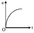
B
C
D
Solution
(B) When the switch $S$ is closed at $t=0$,the current $i$ in the $RL$ circuit grows according to the equation:
$i = \frac{E}{R} (1 - e^{-tR/L})$
This is an increasing exponential function starting from $i=0$ at $t=0$ and approaching $i=E/R$ as $t \to \infty$. This behavior is represented by graph $D$.
The induced $emf$ $e$ across the inductor $L$ is given by:
$e = L \frac{di}{dt} = L \frac{d}{dt} [\frac{E}{R} (1 - e^{-tR/L})] = L \cdot \frac{E}{R} \cdot \frac{R}{L} e^{-tR/L} = E e^{-tR/L}$
At $t=0$,$e=E$,and as $t \to \infty$,$e \to 0$. This is a decreasing exponential function,which is represented by graph $C$.
Therefore,graph $C$ represents $e$ and graph $D$ represents $i$.
0 likes
View Solution82
MediumMCQ
$A$ coil carrying a steady current is short-circuited. The current in it decreases $\alpha$ times in $t_0$. The time constant of the circuit is:-
A
$\tau = t_0 \log_e \alpha$
B
$\tau = \frac{t_0}{\log_e \alpha}$
C
$\tau = \frac{t_0}{\alpha}$
D
$\tau = \frac{t_0}{\alpha - 1}$
Solution
(B) For a short-circuited $RL$ circuit,the current at time $t$ is given by $I = I_0 e^{-t/\tau}$,where $\tau$ is the time constant.
Given that at $t = t_0$,the current becomes $I = \frac{I_0}{\alpha}$.
Substituting these values into the equation:
$\frac{I_0}{\alpha} = I_0 e^{-t_0/\tau}$
$\frac{1}{\alpha} = e^{-t_0/\tau}$
Taking the natural logarithm on both sides:
$\ln(1/\alpha) = -t_0/\tau$
$-\ln(\alpha) = -t_0/\tau$
$\ln(\alpha) = t_0/\tau$
Therefore,the time constant is $\tau = \frac{t_0}{\ln(\alpha)}$ or $\tau = \frac{t_0}{\log_e \alpha}$.
0 likes
View Solution83
EasyMCQ
In the circuit shown,the final current through the $30\, \Omega$ resistance when the circuit is completed is ......... $A$.
A
$3$
B
$0.1$
C
$5$
D
$0.5$
Solution
(B) When the switch $K$ is closed,the circuit reaches a steady state after a long time.
In the steady state,the inductor acts as a short circuit (ideal inductor with zero resistance).
Since the inductor is connected in parallel with the $20\, \Omega$ resistor,the entire current will flow through the inductor,effectively short-circuiting the $20\, \Omega$ resistor.
Therefore,the equivalent resistance of the circuit is only the $30\, \Omega$ resistor.
The current $I$ flowing through the $30\, \Omega$ resistor is given by Ohm's law:
$I = \frac{V}{R} = \frac{3\, V}{30\, \Omega} = 0.1\, A$.
0 likes
View Solution84
MediumMCQ
$A$ coil of inductance $0.20 \, H$ is connected in series with a switch and a cell of $emf$ $1.6 \, V$. The total resistance of the circuit is $4.0 \, \Omega$. What is the initial rate of growth of the current when the switch is closed? (in $A \, s^{-1}$)
A
$0.050$
B
$0.40$
C
$0.13$
D
$8$
Solution
(D) The equation for an $LR$ circuit is given by $V = IR + L \frac{dI}{dt}$.
At the instant the switch is closed $(t = 0)$,the current $I$ in the circuit is $0$.
Substituting $I = 0$ into the equation,we get $V = L \frac{dI}{dt}$.
Therefore,the initial rate of growth of the current is $\frac{dI}{dt} = \frac{V}{L}$.
Given $V = 1.6 \, V$ and $L = 0.20 \, H$,we have $\frac{dI}{dt} = \frac{1.6}{0.20} = 8 \, A \, s^{-1}$.
0 likes
View Solution85
EasyMCQ
The total heat produced in resistor $R$ in an $RL$ circuit when the current in the inductor decreases from $I_0$ to $0$ is
A
$LI_0^2$
B
$\frac{1}{2}LI_0^2$
C
$\frac{3}{2}LI_0^2$
D
$\frac{1}{3}LI_0^2$
Solution
(B) The power dissipated in the resistor is given by $P = I^2 R$.
Since the current through the resistor varies with time,we must integrate the power over time to find the total heat energy $W$.
$W = \int_{0}^{\infty} I^2 R \, dt$
The current in an $RL$ circuit during decay is given by $I = I_0 e^{-(R/L)t}$.
Substituting this into the integral:
$W = \int_{0}^{\infty} (I_0 e^{-(R/L)t})^2 R \, dt = \int_{0}^{\infty} I_0^2 R e^{-(2R/L)t} \, dt$
$W = I_0^2 R \left[ \frac{e^{-(2R/L)t}}{-(2R/L)} \right]_{0}^{\infty} = I_0^2 R \left( 0 - \left( -\frac{L}{2R} \right) \right) = \frac{1}{2} L I_0^2$.
Alternatively,by the law of conservation of energy,the total heat produced in the resistor must equal the total energy initially stored in the magnetic field of the inductor,which is $U = \frac{1}{2} L I_0^2$.
0 likes
View Solution86
MediumMCQ
Given $L_1 = 1\, mH, R_1 = 1\,\Omega, L_2 = 2\,mH, R_2 = 2\,\Omega$. Neglecting mutual inductance,find the time constant (in $ms$) for the circuit shown.
A
$1$
B
$2$
C
$3$
D
$4$
Solution
(A) The circuit consists of two inductors $L_1$ and $L_2$ in series and two resistors $R_1$ and $R_2$ in series.
For inductors in series,the equivalent inductance is $L = L_1 + L_2 = 1\, mH + 2\, mH = 3\, mH$.
For resistors in series,the equivalent resistance is $R = R_1 + R_2 = 1\, \Omega + 2\, \Omega = 3\, \Omega$.
The time constant $\tau$ for an $RL$ circuit is given by $\tau = \frac{L}{R}$.
Substituting the values,we get $\tau = \frac{3\, mH}{3\, \Omega} = 1\, ms$.
0 likes
View Solution87
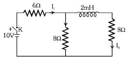
DifficultMCQ
In the circuit shown in the figure, what is the value of $I_1$ just after pressing the key $K$?
A
$\frac{5}{7} \, A$
B
$\frac{5}{11} \, A$
C
$1 \, A$
D
None of the above
Solution
(A) Just after pressing the key $K$ (at $t = 0$), the inductor acts as an open circuit because it opposes any instantaneous change in current.
Therefore, the branch containing the inductor and the $8 \, \Omega$ resistor is effectively disconnected.
The circuit simplifies to a $10 \, V$ battery in series with a $6 \, \Omega$ resistor and an $8 \, \Omega$ resistor connected in parallel to the source.
However, since the inductor branch is open, the current $I_1$ flows through the $6 \, \Omega$ resistor and then entirely through the $8 \, \Omega$ resistor connected in parallel.
The equivalent resistance of the circuit is $R_{eq} = 6 \, \Omega + 8 \, \Omega = 14 \, \Omega$.
The current $I_1$ is given by $I_1 = \frac{V}{R_{eq}} = \frac{10 \, V}{14 \, \Omega} = \frac{5}{7} \, A$.
0 likes
View Solution88
MediumMCQ
In an $LR$ circuit,the current increases to one-fourth of its maximum value in $4 \, sec$. What is the time constant of the circuit?
A
$2 \, \log_e 2$
B
$\frac{4}{\log_e 2}$
C
$\frac{4}{\log_e (4/3)}$
D
$\frac{\log_e 2}{2}$
Solution
(C) The growth of current in an $LR$ circuit is given by $I = I_0 (1 - e^{-t/\tau})$,where $\tau$ is the time constant.
Given that at $t = 4 \, sec$,$I = \frac{I_0}{4}$.
Substituting these values: $\frac{I_0}{4} = I_0 (1 - e^{-4/\tau})$.
$\frac{1}{4} = 1 - e^{-4/\tau} \implies e^{-4/\tau} = 1 - \frac{1}{4} = \frac{3}{4}$.
Taking the natural logarithm on both sides: $-\frac{4}{\tau} = \log_e (3/4)$.
$-\frac{4}{\tau} = \log_e 3 - \log_e 4$.
$\frac{4}{\tau} = \log_e 4 - \log_e 3 = \log_e (4/3)$.
Therefore,$\tau = \frac{4}{\log_e (4/3)} \, sec$.
0 likes
View Solution89
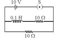
MediumMCQ
In the circuit shown,the switch $S$ is initially open. The switch $S$ is closed at $t = 0$. The difference between the maximum and minimum current that can flow in the circuit is.....$A$.
A
$2$
B
$3$
C
$1$
D
Nothing can be concluded
Solution
(C) The circuit consists of two parallel branches connected to a $10 \, V$ battery.
Branch $1$ contains an inductor $(0.1 \, H)$ and a resistor $(10 \, \Omega)$ in series.
Branch $2$ contains a resistor $(10 \, \Omega)$.
At $t = 0$ (just after closing the switch),the inductor acts as an open circuit due to the back $EMF$. Thus,no current flows through the first branch. The total current in the circuit is only through the second branch: $i_{min} = \frac{10 \, V}{10 \, \Omega} = 1 \, A$.
At $t = \infty$ (long after closing the switch),the inductor acts as a short circuit (zero resistance). The total current is the sum of currents in both branches: $i_{branch1} = \frac{10 \, V}{10 \, \Omega} = 1 \, A$ and $i_{branch2} = \frac{10 \, V}{10 \, \Omega} = 1 \, A$.
Thus,$i_{max} = 1 \, A + 1 \, A = 2 \, A$.
The difference between the maximum and minimum current is $i_{max} - i_{min} = 2 \, A - 1 \, A = 1 \, A$.
0 likes
View Solution90
MediumMCQ
An inductor $L$,a resistance $R$,and two identical bulbs $B_1$ and $B_2$ are connected to a battery through a switch $S$ as shown in the figure. The resistance $R$ is the same as that of the coil that makes $L$. Which of the following statements gives the correct description of the happenings when the switch $S$ is closed?
A
The bulb $B_2$ lights up earlier than $B_1$ and finally both the bulbs shine equally bright.
B
$B_1$ lights up earlier and finally both the bulbs acquire equal brightness.
C
$B_2$ lights up earlier and finally $B_1$ shines brighter than $B_2$.
D
$B_1$ and $B_2$ light up together with equal brightness all the time.
Solution
(A) When the switch $S$ is closed,the current in the circuit containing the inductor $L$ grows gradually due to the back $EMF$ induced in the inductor,which opposes the change in current $(e = -L \frac{di}{dt})$.
In the branch containing the resistor $R$,the current reaches its steady-state value almost instantaneously.
Therefore,the bulb $B_2$ (in the resistor branch) lights up earlier than the bulb $B_1$ (in the inductor branch).
As time passes,the current in the inductor branch increases and eventually reaches the same steady-state value as the resistor branch,because the resistance of the inductor coil is equal to $R$.
Thus,finally,both bulbs shine with equal brightness.
0 likes
View Solution91
MediumMCQ
In the following figure,what is the final value of current in the $10 \, \Omega$ resistor when the plug of key $K$ is inserted?
A
$(2/20) \, A$
B
$(2/30) \, A$
C
$(2/10) \, A$
D
Zero
Solution
(D) When the key $K$ is closed,the circuit reaches a steady state.
In a steady state,an ideal inductor acts as a short circuit (zero resistance).
Since the inductor is connected in parallel with the $10 \, \Omega$ resistor,the entire current will flow through the inductor path,bypassing the $10 \, \Omega$ resistor.
Therefore,the final current flowing through the $10 \, \Omega$ resistor is $0 \, A$.
0 likes
View Solution92
DifficultMCQ
The time constant of a circuit is $10 \, s$. When a resistance of $10 \, \Omega$ is connected in series to the circuit,the time constant becomes $2 \, s$. The self-inductance of the circuit is ....... $H$.
A
$2.5$
B
$5$
C
$15$
D
$25$
Solution
(D) The time constant $\tau$ of an $LR$ circuit is given by $\tau = \frac{L}{R}$.
Initially,$\frac{L}{R} = 10$,which implies $L = 10R$ .......... $(1)$
When a resistance of $10 \, \Omega$ is added in series,the new resistance becomes $(R + 10) \, \Omega$.
The new time constant is $\frac{L}{R + 10} = 2$,which implies $L = 2(R + 10) = 2R + 20$ .......... $(2)$
Equating $(1)$ and $(2)$:
$10R = 2R + 20$
$8R = 20$
$R = 2.5 \, \Omega$
Substituting $R$ into equation $(1)$:
$L = 10 \times 2.5 = 25 \, H$.
0 likes
View Solution93
EasyMCQ
Assertion : The resistance offered by an inductor in a $d.c.$ circuit is always constant.
Reason : The resistance of an inductor in a steady state is non-zero.
Reason : The resistance of an inductor in a steady state is non-zero.
A
If both Assertion and Reason are correct and the Reason is a correct explanation of the Assertion.
B
If both Assertion and Reason are correct but Reason is not a correct explanation of the Assertion.
C
If the Assertion is correct but Reason is incorrect.
D
If both the Assertion and Reason are incorrect.
Solution
(D) An inductor in a $d.c.$ circuit behaves as an open circuit at $t = 0$ (infinite resistance) and as a short circuit at steady state ($t \to \infty$,zero resistance).
Since the resistance changes from infinity to zero,the assertion that it is 'always constant' is incorrect.
In a steady state,an ideal inductor has zero resistance,so the statement that it is 'non-zero' is also incorrect.
Therefore,both the Assertion and the Reason are incorrect.
Since the resistance changes from infinity to zero,the assertion that it is 'always constant' is incorrect.
In a steady state,an ideal inductor has zero resistance,so the statement that it is 'non-zero' is also incorrect.
Therefore,both the Assertion and the Reason are incorrect.
0 likes
View Solution94
MediumMCQ
An emf of $20\; V$ is applied at time $t=0$ to a circuit containing in series $10\; mH$ inductor and $5\; \Omega$ resistor. The ratio of the currents at time $t=\infty$ and at $t=40\; ms$ is close to: (Take $e^{2}=7.389$)
A
$1.06$
B
$1.15$
C
$1.46$
D
$0.84$
Solution
(B) The current in an $RL$ circuit at time $t$ is given by $i(t) = i_0(1 - e^{-Rt/L})$,where $i_0 = V/R$ is the steady-state current at $t = \infty$.
Given $V = 20\; V$,$R = 5\; \Omega$,and $L = 10\; mH = 10 \times 10^{-3}\; H = 0.01\; H$.
The time constant $\tau = L/R = 0.01 / 5 = 0.002\; s = 2\; ms$.
At $t = 40\; ms$,the exponent is $-Rt/L = -t/\tau = -40\; ms / 2\; ms = -20$.
Wait,checking the time provided: if $t = 40\; ms$,then $t/\tau = 20$. If $t = 40\; s$,then $t/\tau = 20000$. Assuming the question implies $t = 4\; ms$ to match the $e^2$ hint: $t/\tau = 4\; ms / 2\; ms = 2$.
Then $i(4\; ms) = i_0(1 - e^{-2})$.
The ratio $i(\infty) / i(4\; ms) = i_0 / [i_0(1 - e^{-2})] = 1 / (1 - 1/e^2) = e^2 / (e^2 - 1)$.
Using $e^2 = 7.389$,the ratio is $7.389 / (7.389 - 1) = 7.389 / 6.389 \approx 1.156$.
0 likes
View Solution95
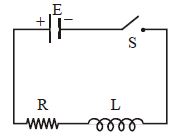
DifficultMCQ
As shown in the figure,a battery of $emf \; \varepsilon$ is connected to an inductor $L$ and resistance $R$ in series. The switch $S$ is closed at $t=0$. The total charge that flows from the battery between $t=0$ and $t=t_{c}$ ($t_{c}$ is the time constant of the circuit) is
A
$\frac{\varepsilon L}{R^{2}}\left(1-\frac{1}{e}\right)$
B
$\frac{\varepsilon L}{e R^{2}}$
C
$\frac{\varepsilon L}{R^{2}}$
D
$\frac{\varepsilon R}{e L^{2}}$
Solution
(B) The current in an $LR$ circuit at time $t$ is given by $i(t) = \frac{\varepsilon}{R} (1 - e^{-Rt/L})$.
Let $T_c = \frac{L}{R}$ be the time constant. Then $i(t) = \frac{\varepsilon}{R} (1 - e^{-t/T_c})$.
The total charge $q$ flowing from $t=0$ to $t=T_c$ is given by the integral of current with respect to time:
$q = \int_{0}^{T_c} i(t) dt = \int_{0}^{T_c} \frac{\varepsilon}{R} (1 - e^{-t/T_c}) dt$
$q = \frac{\varepsilon}{R} \left[ t - \frac{e^{-t/T_c}}{-1/T_c} \right]_{0}^{T_c} = \frac{\varepsilon}{R} \left[ t + T_c e^{-t/T_c} \right]_{0}^{T_c}$
$q = \frac{\varepsilon}{R} \left[ (T_c + T_c e^{-1}) - (0 + T_c e^{0}) \right]$
$q = \frac{\varepsilon}{R} [T_c + T_c e^{-1} - T_c] = \frac{\varepsilon}{R} T_c e^{-1}$
Substituting $T_c = \frac{L}{R}$:
$q = \frac{\varepsilon}{R} \cdot \frac{L}{R} \cdot \frac{1}{e} = \frac{\varepsilon L}{e R^2}$.
0 likes
View Solution96
Difficult
Find the current in the sliding rod $AB$ (resistance $= R$) for the arrangement shown in the figure. The magnetic field $\vec{B}$ is constant and directed out of the paper. The parallel wires have no resistance,and the velocity $v$ is constant. The switch $S$ is closed at time $t = 0$.
Solution
(N/A) rod of length $d$ moves with velocity $v$ perpendicular to a magnetic field $B$,inducing an electromotive force (emf) $\varepsilon = Bvd$ between its ends.
When the switch $S$ is closed at $t = 0$,the capacitor begins to charge. Let $Q(t)$ be the charge on the capacitor at time $t$.
Applying Kirchhoff's voltage law to the circuit:
$\varepsilon = V_R + V_C$
$Bvd = IR + \frac{Q}{C}$
Since $I = \frac{dQ}{dt}$,we have:
$R \frac{dQ}{dt} + \frac{Q}{C} = Bvd$
$\frac{dQ}{dt} + \frac{Q}{RC} = \frac{Bvd}{R}$
This is a first-order linear differential equation. The general solution for $Q(t)$ is:
$Q(t) = BvdC + A e^{-t/RC}$
At $t = 0$,the charge $Q(0) = 0$,so $0 = BvdC + A$,which gives $A = -BvdC$.
Thus,$Q(t) = BvdC(1 - e^{-t/RC})$.
The current $I(t)$ is the derivative of charge with respect to time:
$I(t) = \frac{dQ}{dt} = \frac{d}{dt} [BvdC(1 - e^{-t/RC})]$
$I(t) = BvdC \cdot \left( \frac{1}{RC} \right) e^{-t/RC}$
$I(t) = \frac{Bvd}{R} e^{-t/RC}$
0 likes
View Solution97
Difficult
Find the current in the sliding rod $AB$ (resistance $= R$) for the arrangement shown in the figure. $\vec{B}$ is constant and is directed out of the paper. The parallel wires have no resistance. $v$ is constant. The switch $S$ is closed at time $t = 0$.
Solution
(N/A) When a rod of length $d$ moves with velocity $v$ perpendicular to a magnetic field,an electromotive force (emf) is induced between the two ends of the rod.
The induced emf is $\varepsilon = Bvd$.
When the switch $S$ is closed at $t = 0$,the current in the inductor starts to increase.
Let the current in the circuit be $I$ at time $t$. According to Kirchhoff's voltage law:
$\varepsilon = V_R + V_L$
$Bvd = IR + L \frac{dI}{dt}$
Rearranging the terms,we get the linear differential equation:
$\frac{dI}{dt} + \frac{R}{L}I = \frac{Bvd}{L}$
The solution to this linear differential equation is of the form:
$I(t) = \frac{Bvd}{R} + A e^{-\frac{R}{L}t}$
Using the initial condition that at $t = 0$,$I = 0$:
$0 = \frac{Bvd}{R} + A \implies A = -\frac{Bvd}{R}$
Substituting $A$ back into the equation:
$I(t) = \frac{Bvd}{R} \left(1 - e^{-\frac{R}{L}t}\right)$
This is the required expression for the current in the rod as a function of time.
0 likes
View Solution98
DifficultMCQ
$A$ series $L-R$ circuit is connected to a battery of emf $V$. If the circuit is switched on at $t = 0$,then the time at which the energy stored in the inductor reaches $\left(\frac{1}{n}\right)$ times of its maximum value,is
A
$\frac{L}{R} \ln \left(\frac{\sqrt{n}}{\sqrt{n}-1}\right)$
B
$\frac{L}{R} \ln \left(\frac{\sqrt{n}}{\sqrt{n}+1}\right)$
C
$\frac{L}{R} \ln \left(\frac{\sqrt{n}}{\sqrt{n-1}}\right)$
D
$\frac{L}{R} \ln \left(\frac{\sqrt{n}+1}{\sqrt{n}-1}\right)$
Solution
(A) The maximum energy stored in the inductor is $U_{\max} = \frac{1}{2} L I_{\max}^2$.
The current in the $L-R$ circuit at time $t$ is given by $i = I_{\max}(1 - e^{-Rt/L})$.
We want the energy $U$ to be $\frac{U_{\max}}{n}$. Since $U = \frac{1}{2} L i^2$,this implies $\frac{1}{2} L i^2 = \frac{1}{n} \left(\frac{1}{2} L I_{\max}^2\right)$,which simplifies to $i = \frac{I_{\max}}{\sqrt{n}}$.
Substituting this into the current equation: $\frac{I_{\max}}{\sqrt{n}} = I_{\max}(1 - e^{-Rt/L})$.
Dividing by $I_{\max}$,we get $\frac{1}{\sqrt{n}} = 1 - e^{-Rt/L}$,or $e^{-Rt/L} = 1 - \frac{1}{\sqrt{n}} = \frac{\sqrt{n}-1}{\sqrt{n}}$.
Taking the natural logarithm on both sides: $-\frac{Rt}{L} = \ln \left(\frac{\sqrt{n}-1}{\sqrt{n}}\right)$.
Multiplying by $-1$ and rearranging: $\frac{Rt}{L} = -\ln \left(\frac{\sqrt{n}-1}{\sqrt{n}}\right) = \ln \left(\frac{\sqrt{n}}{\sqrt{n}-1}\right)$.
Therefore,$t = \frac{L}{R} \ln \left(\frac{\sqrt{n}}{\sqrt{n}-1}\right)$.
0 likes
View Solution99
DifficultMCQ
The time taken for the magnetic energy to reach $25\%$ of its maximum value,when a solenoid of resistance $R$ and inductance $L$ is connected to a battery,is:
A
$\frac{L}{R} \ln 5$
B
infinite
C
$\frac{L}{R} \ln 2$
D
$\frac{L}{R} \ln 10$
Solution
(C) The magnetic energy stored in an inductor is given by $U = \frac{1}{2} L i^2$.
Let $U_{max}$ be the maximum energy,which occurs when the current reaches its maximum value $i_0$. Thus,$U_{max} = \frac{1}{2} L i_0^2$.
We are given that the energy reaches $25\%$ of its maximum value:
$U = 0.25 U_{max} = \frac{1}{4} (\frac{1}{2} L i_0^2) = \frac{1}{2} L (\frac{i_0}{2})^2$.
Comparing this with $U = \frac{1}{2} L i^2$,we find that the current $i$ must be $\frac{i_0}{2}$.
The expression for current in an $RL$ circuit during charging is $i = i_0 (1 - e^{-Rt/L})$.
Setting $i = \frac{i_0}{2}$,we get: $\frac{i_0}{2} = i_0 (1 - e^{-Rt/L})$.
$\frac{1}{2} = 1 - e^{-Rt/L} \Rightarrow e^{-Rt/L} = \frac{1}{2}$.
Taking the natural logarithm on both sides: $-\frac{Rt}{L} = \ln(\frac{1}{2}) = -\ln 2$.
Therefore,$t = \frac{L}{R} \ln 2$.
0 likes
View Solution100
DifficultMCQ
The current $(i)$ at time $t = 0$ and $t = \infty$ respectively for the given circuit is
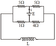
A
$\frac{18 E }{55}, \frac{5 E }{18}$
B
$\frac{10 E }{33}, \frac{5 E }{18}$
C
$\frac{5 E }{18}, \frac{18 E }{55}$
D
$\frac{5 E }{18}, \frac{10 E }{33}$
Solution
(D) At $t = 0$,the inductor acts as an open circuit (infinite resistance). The circuit simplifies to two parallel branches: one with $(5 \Omega + 1 \Omega) = 6 \Omega$ and the other with $(5 \Omega + 4 \Omega) = 9 \Omega$.
These two branches are in parallel,so the equivalent resistance is $R_{eq} = (6 \times 9) / (6 + 9) = 54 / 15 = 18 / 5 \ \Omega$.
The current $i$ at $t = 0$ is $i_1 = E / R_{eq} = E / (18 / 5) = 5E / 18$.
At $t = \infty$,the inductor acts as a short circuit (zero resistance). The circuit becomes a bridge-like structure where the $5 \Omega$ and $5 \Omega$ resistors are in parallel,and the $1 \Omega$ and $4 \Omega$ resistors are in parallel.
The equivalent resistance is $R_{eq} = (5 \parallel 5) + (1 \parallel 4) = (2.5) + (4 / 5) = 2.5 + 0.8 = 3.3 \ \Omega = 33 / 10 \ \Omega$.
The current $i$ at $t = \infty$ is $i_2 = E / R_{eq} = E / (33 / 10) = 10E / 33$.

0 likes
View SolutionElectromagnetic Induction — R-L D.C. Circuit · Frequently Asked Questions
1Are these Electromagnetic Induction questions useful for JEE and NEET?
Yes. All questions in this section are mapped to JEE Main and NEET exam patterns. Previous year questions from JEE Main, NEET, GUJCET and state-level exams are included with full solutions.
2Can I switch to Hindi or Gujarati for these questions?
Yes. Use the language tabs in the hero section or the sidebar to view the same questions and solutions in English, Hindi or Gujarati.
3How do I generate a question paper from this subtopic?
Use the Vedclass Exam Paper Generator — select the chapter and subtopic, set difficulty, and generate Sets A, B, C, D automatically. First 3 chapters of every subject are free.
Vedclass Products
For Students
Vedclass Test Series
Mock tests in real JEE/NEET style with performance analysis. 5-day free trial.
Start Free TrialFor Teachers
Exam Paper Generator
Generate Set A/B/C/D papers from this chapter in 2 minutes. 3 chapters free.
Try FreeFor Institutes
Online Exam Module
Live online exams with unlimited students, 360° analytics & white-label branding.
See DemoFor Teachers & Institutes
Generate a Electromagnetic Induction Exam Paper in 2 Minutes
Select subtopic & difficulty — Sets A, B, C, D auto-generated with No Repeat logic.
First 3 chapters of every subject are free — no payment required.