
A English
R-L D.C. Circuit Questions in English
Class 12 Physics · Electromagnetic Induction · R-L D.C. Circuit
135+
Questions
English
Language
100%
With Solutions
Showing 33 of 135 questions in English
101
DifficultMCQ
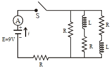
The figure shows a circuit that contains three resistors with resistance $R = 2.0 \, \Omega$, two inductors with inductance $L = 2.0 \, mH$, and an ideal battery with $emf$ $E = 9 \, V$. The current $i$ just after the switch $S$ is closed will be .... $A$.
A
$2.25$
B
$3.0$
C
$3.37$
D
$9.0$
Solution
(A) Just after the switch $S$ is closed, the current through the inductors cannot change instantaneously. Since the current was zero before closing the switch, it remains zero immediately after closing the switch.
Therefore, the branches containing inductors act as open circuits (infinite resistance).
The circuit simplifies to a series combination of the battery and two resistors of resistance $R$ each.
The equivalent resistance of the circuit is $R_{eq} = R + R = 2.0 \, \Omega + 2.0 \, \Omega = 4.0 \, \Omega$.
The current $i$ in the circuit is given by Ohm's law:
$i = \frac{E}{R_{eq}} = \frac{9 \, V}{4.0 \, \Omega} = 2.25 \, A$.
0 likes
View Solution102
DifficultMCQ
An inductor coil stores $64 \, J$ of magnetic field energy and dissipates energy at the rate of $640 \, W$ when a current of $8 \, A$ is passed through it. If this coil is joined across an ideal battery,find the time constant of the circuit in seconds.
A
$0.4$
B
$0.8$
C
$0.125$
D
$0.2$
Solution
(D) The energy stored in an inductor is given by $U = \frac{1}{2} L i^2$. Given $U = 64 \, J$ and $i = 8 \, A$,we have $64 = \frac{1}{2} \times L \times (8)^2$. This simplifies to $64 = 32L$,so $L = 2 \, H$.
The rate of energy dissipation (power) is given by $P = i^2 R$. Given $P = 640 \, W$ and $i = 8 \, A$,we have $640 = (8)^2 \times R$. This simplifies to $640 = 64R$,so $R = 10 \, \Omega$.
The time constant $\tau$ of an $LR$ circuit is given by $\tau = \frac{L}{R}$. Substituting the values,$\tau = \frac{2}{10} = 0.2 \, s$.
0 likes
View Solution103
DifficultMCQ
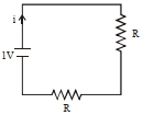
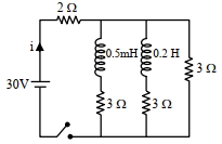
For the given circuit,the current $i$ through the battery when the key is closed and the steady state has been reached is .....$A$.
A
$6$
B
$25$
C
$10$
D
$0$
Solution
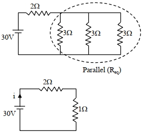
(C) In steady state,an inductor behaves as a conducting wire (short circuit).
Therefore,the two inductors in the circuit act as simple wires.
The circuit now consists of three resistors of $3 \, \Omega$ each,connected in parallel.
The equivalent resistance of these three parallel resistors is given by:
$\frac{1}{R_{p}} = \frac{1}{3} + \frac{1}{3} + \frac{1}{3} = \frac{3}{3} = 1 \, \Omega^{-1}$
$\Rightarrow R_{p} = 1 \, \Omega$
This parallel combination is in series with the $2 \, \Omega$ resistor.
Total equivalent resistance of the circuit is $R_{eq} = 2 \, \Omega + R_{p} = 2 \, \Omega + 1 \, \Omega = 3 \, \Omega$.
The current $i$ through the battery is given by Ohm's law:
$i = \frac{V}{R_{eq}} = \frac{30 \, V}{3 \, \Omega} = 10 \, A$.
0 likes
View Solution104
DifficultMCQ
An inductor of $10\, \text{mH}$ is connected to a $20\, \text{V}$ battery through a resistor of $10\, \text{k}\Omega$ and a switch. After a long time,when maximum current is set up in the circuit,the current is switched off. The current in the circuit after $1\, \mu\text{s}$ is $\frac{x}{100}\, \text{mA}$. Then $x$ is equal to ...... . (Take $e^{-1} = 0.37$)
A
$71$
B
$73$
C
$74$
D
$80$
Solution
(C) The maximum current $I_{\max}$ in the $LR$ circuit is given by $I_{\max} = \frac{V}{R} = \frac{20\, \text{V}}{10 \times 10^3\, \Omega} = 2 \times 10^{-3}\, \text{A} = 2\, \text{mA}$.
When the switch is opened,the circuit acts as an $LR$ decay circuit. The current at time $t$ is given by $I(t) = I_{\max} e^{-Rt/L}$.
Given $R = 10^4\, \Omega$,$L = 10 \times 10^{-3}\, \text{H}$,and $t = 1 \times 10^{-6}\, \text{s}$.
The exponent is $-\frac{Rt}{L} = -\frac{10^4 \times 10^{-6}}{10 \times 10^{-3}} = -\frac{10^{-2}}{10^{-2}} = -1$.
Thus,$I = 2 \times e^{-1}\, \text{mA}$.
Using $e^{-1} = 0.37$,we get $I = 2 \times 0.37\, \text{mA} = 0.74\, \text{mA}$.
Expressing this as $\frac{x}{100}\, \text{mA}$,we have $\frac{x}{100} = 0.74$,which implies $x = 74$.
1 likes
View Solution105
DifficultMCQ
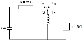
Consider an electrical circuit containing a two-way switch $S$. Initially,$S$ is open and then $T_{1}$ is connected to $T_{2}$. As the current in $R = 6 \, \Omega$ attains a maximum value of steady-state level,$T_{1}$ is disconnected from $T_{2}$ and immediately connected to $T_{3}$. The potential drop across the $r = 3 \, \Omega$ resistor immediately after $T_{1}$ is connected to $T_{3}$ is $.... \, V$. (Round off to the nearest integer)
A
$2$
B
$3$
C
$5$
D
$7$
Solution
(B) $1$. When $T_{1}$ and $T_{2}$ are connected,the circuit consists of the $6 \, V$ battery,the $R = 6 \, \Omega$ resistor,and the inductor $L$ in series.
$2$. At steady state,the inductor acts as a short circuit (zero resistance). The steady-state current $I$ flowing through the inductor is given by $I = \frac{V}{R} = \frac{6 \, V}{6 \, \Omega} = 1 \, A$.
$3$. When $T_{1}$ is disconnected from $T_{2}$ and immediately connected to $T_{3}$,the inductor $L$ is now in series with the $r = 3 \, \Omega$ resistor. Because the current through an inductor cannot change instantaneously,the current $I = 1 \, A$ continues to flow through the new circuit loop.
$4$. The potential drop $V_{r}$ across the $r = 3 \, \Omega$ resistor immediately after the switch is flipped is $V_{r} = I \times r = 1 \, A \times 3 \, \Omega = 3 \, V$.
0 likes
View Solution106
MediumMCQ
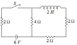
For the given circuit,the current through the battery of $6\,V$ just after closing the switch $S$ will be $.......A$.
A
$3$
B
$2$
C
$0$
D
$1$
Solution
(D) Just after closing the switch $S$ $(t = 0)$,the inductor opposes any change in current,so it behaves as an open circuit (infinite resistance).
Therefore,the branch containing the inductor carries no current.
The circuit simplifies to the $6\,V$ battery in series with the $2\,\Omega$ resistor and the $4\,\Omega$ resistor.
The total resistance of the circuit is $R_{eq} = 2\,\Omega + 4\,\Omega = 6\,\Omega$.
Using Ohm's law,the current through the battery is $I = \frac{V}{R_{eq}} = \frac{6\,V}{6\,\Omega} = 1\,A$.
0 likes
View Solution107
DifficultMCQ
$A$ coil of inductance $1\,H$ and resistance $100\,\Omega$ is connected to a battery of $6\,V$. Determine approximately:
$(a)$ The time elapsed before the current acquires half of its steady-state value.
$(b)$ The energy stored in the magnetic field associated with the coil at an instant $15\,ms$ after the circuit is switched on. (Given $\ln 2 = 0.693$,$e^{-3/2} = 0.25$)
$(a)$ The time elapsed before the current acquires half of its steady-state value.
$(b)$ The energy stored in the magnetic field associated with the coil at an instant $15\,ms$ after the circuit is switched on. (Given $\ln 2 = 0.693$,$e^{-3/2} = 0.25$)
A
$t = 10\,ms; U = 2\,mJ$
B
$t = 10\,ms; U = 1\,mJ$
C
$t = 7\,ms; U = 1\,mJ$
D
$t = 7\,ms; U = 2\,mJ$
Solution
(C) The current in an $LR$ circuit is given by $i = \frac{E}{R}(1 - e^{-t/\tau})$,where $\tau = \frac{L}{R} = \frac{1}{100} = 0.01\,s = 10\,ms$.
$(a)$ For the current to reach half its steady-state value $(i = \frac{E}{2R})$:
$\frac{E}{2R} = \frac{E}{R}(1 - e^{-t/\tau})$
$0.5 = 1 - e^{-t/\tau} \implies e^{-t/\tau} = 0.5$
$t = \tau \ln 2 = 10\,ms \times 0.693 = 6.93\,ms \approx 7\,ms$.
$(b)$ At $t = 15\,ms$,$t/\tau = 15/10 = 1.5$:
$i = \frac{6}{100}(1 - e^{-1.5}) = 0.06(1 - 0.25) = 0.06 \times 0.75 = 0.045\,A$.
The energy stored is $U = \frac{1}{2}Li^2 = \frac{1}{2} \times 1 \times (0.045)^2 = 0.5 \times 0.002025 \approx 0.001\,J = 1\,mJ$.
2 likes
View Solution108
DifficultMCQ
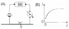
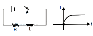
$A$ blackbox $(BB)$ which may contain a combination of electrical circuit elements (resistor, capacitor or inductor) is connected with other external circuit elements as shown in figure $(A)$. After the switch $S$ is closed at time $t=0$, the current $I$ as a function of time $t$ is shown in figure $(B)$. From this, we can infer that the blackbox contains:
A
a resistor and a capacitor in series
B
a resistor and a capacitor in parallel
C
a resistor and an inductor in series
D
a resistor and an inductor in parallel
Solution
(C) The graph in figure $(B)$ shows that the current $I$ starts from $0$ at $t=0$ and increases exponentially with time, eventually reaching a steady-state value.
In a series $RC$ circuit, the current decreases exponentially after the switch is closed.
In a series $RL$ circuit, the current $I$ is given by $I(t) = \frac{V}{R}(1 - e^{-Rt/L})$.
At $t=0$, $I(0) = 0$, and as $t \to \infty$, $I \to V/R$, which matches the behavior shown in the graph.
Therefore, the blackbox contains a resistor and an inductor in series.
0 likes
View Solution109
DifficultMCQ
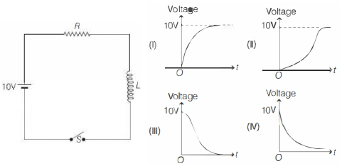
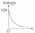
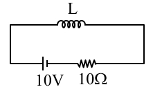
In the circuit shown below,the switch is closed at time $t=0$. Which of the graphs shown below best represents the voltage across the inductor,as seen on an oscilloscope?
A
$I$
B
$II$
C
$III$
D
$IV$
Solution
(D) The correct answer is $IV$.
At $t=0$,when the switch is closed,the current in the circuit is zero because the inductor opposes any instantaneous change in current. Therefore,the potential drop across the resistor $(V_R = iR)$ is zero.
By Kirchhoff's voltage law,the entire source voltage of $10 \, V$ appears across the inductor at $t=0$. Thus,the initial voltage across the inductor is $10 \, V$.
As time passes,the current $i$ in the circuit grows exponentially according to the equation $i(t) = \frac{V}{R} (1 - e^{-Rt/L})$.
The voltage across the inductor is given by $V_L = L \frac{di}{dt} = V e^{-Rt/L}$.
As $t$ increases,the current increases,and the potential drop across the resistor increases,while the potential drop across the inductor decreases exponentially from $10 \, V$ to $0 \, V$.
When the current reaches its maximum steady value,the rate of change of current becomes zero,and the potential drop across the inductor tends to zero. This exponential decay is best represented by graph $IV$.
0 likes
View Solution110
MediumMCQ
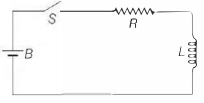
The circuit shown consists of a switch $S$,a battery $B$ of emf $E$,a resistance $R$,and an inductor $L$. What is the current in the circuit at the instant the switch $S$ is closed?
A
$E / R$
B
$E / R(1 - e^{-1})$
C
$\infty$
D
$0$
Solution
(D) When the switch $S$ is closed at time $t = 0$,the inductor $L$ opposes any change in the current flowing through it.
According to Lenz's law,the induced emf in the inductor is given by $\varepsilon = -L(di/dt)$.
At the instant $t = 0$,the current in the circuit is zero,and the inductor acts as an open circuit (infinite resistance) to prevent the sudden change in current.
Therefore,the current in the circuit at the instant the switch is closed is $i = 0$.
0 likes
View Solution111
MediumMCQ
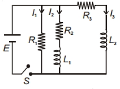
The figure shows an $L-R$ circuit. When the switch $S$ is closed,the currents through resistors $R_1, R_2$ and $R_3$ are $I_1, I_2$ and $I_3$ respectively. The values of $I_1, I_2$ and $I_3$ at $t=0 \, s$ are:
A
$I_1=I_2=I_3=0$
B
$I_1=\frac{E}{R_1}, I_2=I_3=0$
C
$I_1=0, I_2=\frac{E}{R_2}, I_3=\frac{E}{R_3}$
D
$I_1=\frac{E}{R_1}, I_2=\frac{E}{R_2+L_1}, I_3=\frac{E}{R_3+L_3}$
Solution
(B) At $t=0 \, s$,the inductor opposes any sudden change in current. Therefore,it acts as an open circuit (infinite resistance) at the instant the switch is closed.
$1$. The branch containing $R_1$ is purely resistive,so the current $I_1$ flows immediately: $I_1 = \frac{E}{R_1}$.
$2$. The branches containing $L_1$ and $L_2$ act as open circuits at $t=0 \, s$ due to the back electromotive force induced in the inductors.
$3$. Consequently,no current flows through the branches containing inductors at $t=0 \, s$,meaning $I_2 = 0$ and $I_3 = 0$.
Thus,the correct values are $I_1 = \frac{E}{R_1}, I_2 = 0, I_3 = 0$.
0 likes
View Solution112
DifficultMCQ
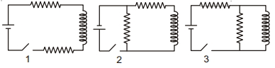
The figure shows three circuits with identical batteries,inductors,and resistors. Rank the circuits according to the currents through the battery just after the switch is closed,greatest first.
A
$I_2 > I_3 > I_1$
B
$I_2 > I_1 > I_3$
C
$I_1 > I_2 > I_3$
D
$I_1 > I_3 > I_2$
Solution
(A) Just after the switch is closed,the inductor acts as an open circuit (infinite resistance) because it opposes any change in current ($I = 0$ through the inductor branch).
For circuit $1$: The inductor is in series with the battery. Thus,the current $I_1 = 0$.
For circuit $2$: The resistor is in parallel with the series combination of the inductor and another resistor. The inductor branch has infinite resistance,so the current flows only through the parallel resistor. Thus,$I_2 = \frac{\varepsilon}{R}$.
For circuit $3$: The inductor is in parallel with a resistor. The inductor branch acts as an open circuit. The battery sees two resistors in series (the one in the main branch and the one in parallel). Thus,$I_3 = \frac{\varepsilon}{2R}$.
Comparing the currents: $I_2 = \frac{\varepsilon}{R}$,$I_3 = \frac{\varepsilon}{2R}$,and $I_1 = 0$.
Therefore,the ranking is $I_2 > I_3 > I_1$.
0 likes
View Solution113
MediumMCQ
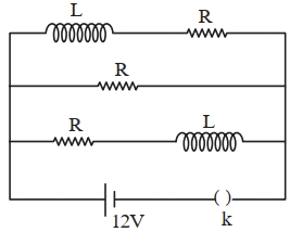
Three identical resistors with resistance $R = 12\,\Omega$ and two identical inductors with self-inductance $L = 5\,mH$ are connected to an ideal battery with an emf of $12\,V$ as shown in the figure. The current through the battery long after the switch has been closed will be $......A$.
A
$1$
B
$2$
C
$3$
D
$4$
Solution
(C) After a long time,an inductor in a $DC$ circuit behaves as a short circuit (a wire with zero resistance).
In the given circuit,there are three parallel branches:
$1$. The top branch contains an inductor $L$ and a resistor $R$. Since the inductor acts as a short circuit,the effective resistance of this branch is $R = 12\,\Omega$.
$2$. The middle branch contains only a resistor $R = 12\,\Omega$.
$3$. The bottom branch contains a resistor $R$ and an inductor $L$. Similarly,the effective resistance of this branch is $R = 12\,\Omega$.
Since all three branches are in parallel and each has an effective resistance of $12\,\Omega$,the equivalent resistance $R_{eq}$ of the circuit is:
$\frac{1}{R_{eq}} = \frac{1}{R} + \frac{1}{R} + \frac{1}{R} = \frac{3}{R}$
$R_{eq} = \frac{R}{3} = \frac{12\,\Omega}{3} = 4\,\Omega$
The current $I$ through the battery is given by Ohm's law:
$I = \frac{V}{R_{eq}} = \frac{12\,V}{4\,\Omega} = 3\,A$.
0 likes
View Solution114
DifficultMCQ
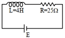
In the given figure,an inductor of $L = 4 \, H$ and a resistor of $R = 25 \, \Omega$ are connected in series with a battery of emf $E$ volt. $\frac{E^a}{2b} \, J/s$ represents the maximum rate at which energy is stored in the magnetic field of the inductor. The numerical value of $\frac{b}{a}$ is ............
A
$24$
B
$23$
C
$25$
D
$22$
Solution
(C) The energy stored in an inductor is given by $U = \frac{1}{2} L I^2$.
The rate of energy storage is $P = \frac{dU}{dt} = L I \frac{dI}{dt}$.
For an $R-L$ circuit,the current at time $t$ is $I = \frac{E}{R} (1 - e^{-tR/L})$.
The rate of change of current is $\frac{dI}{dt} = \frac{E}{L} e^{-tR/L}$.
Substituting these into the power equation:
$P = L \left[ \frac{E}{R} (1 - e^{-tR/L}) \right] \left[ \frac{E}{L} e^{-tR/L} \right] = \frac{E^2}{R} (e^{-tR/L} - e^{-2tR/L})$.
To find the maximum rate,we differentiate $P$ with respect to $t$ and set it to zero:
$\frac{dP}{dt} = \frac{E^2}{R} \left( -\frac{R}{L} e^{-tR/L} + \frac{2R}{L} e^{-2tR/L} \right) = 0$.
This implies $e^{-tR/L} = 2 e^{-2tR/L}$,so $e^{tR/L} = 2$,or $t = \frac{L}{R} \ln 2$.
At this time,$e^{-tR/L} = \frac{1}{2}$.
Substituting this back into the power equation:
$P_{max} = \frac{E^2}{R} \left( \frac{1}{2} - (\frac{1}{2})^2 \right) = \frac{E^2}{R} (\frac{1}{4}) = \frac{E^2}{4R}$.
Given $R = 25 \, \Omega$,we have $P_{max} = \frac{E^2}{4 \times 25} = \frac{E^2}{100}$.
Comparing this with $\frac{E^a}{2b}$,we get $a = 2$ and $b = 50$.
Therefore,$\frac{b}{a} = \frac{50}{2} = 25$.
0 likes
View Solution115
Advanced
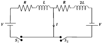
In the figure below,the switches $S_1$ and $S_2$ are closed simultaneously at $t=0$ and a current starts to flow in the circuit. Both the batteries have the same magnitude of the electromotive force (emf) $V$ and the polarities are as indicated in the figure. Ignore mutual inductance between the inductors. The current $I$ in the middle wire reaches its maximum magnitude $I_{\max}$ at time $t=T$. Which of the following statements is (are) true?
$(A)$ $I_{\max}=\frac{V}{2R}$
$(B)$ $I_{\max}=\frac{V}{4R}$
$(C)$ $T=\frac{L}{R} \ln 2$
$(D)$ $T=\frac{2L}{R} \ln 2$
$(A)$ $I_{\max}=\frac{V}{2R}$
$(B)$ $I_{\max}=\frac{V}{4R}$
$(C)$ $T=\frac{L}{R} \ln 2$
$(D)$ $T=\frac{2L}{R} \ln 2$
Solution
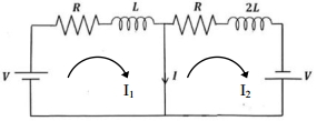
(D) Let $I_1$ be the current in the left loop and $I_2$ be the current in the right loop. The current $I$ in the middle wire is $I = I_2 - I_1$.
For the left loop: $V - I_1 R - L \frac{dI_1}{dt} = 0 \implies I_1(t) = \frac{V}{R}(1 - e^{-(R/L)t})$.
For the right loop: $V - I_2 R - 2L \frac{dI_2}{dt} = 0 \implies I_2(t) = \frac{V}{R}(1 - e^{-(R/2L)t})$.
The current in the middle wire is $I(t) = I_2(t) - I_1(t) = \frac{V}{R} [e^{-(R/L)t} - e^{-(R/2L)t}]$.
To find the maximum current,set $\frac{dI}{dt} = 0$:
$\frac{dI}{dt} = \frac{V}{R} [-\frac{R}{L} e^{-(R/L)t} + \frac{R}{2L} e^{-(R/2L)t}] = 0$.
$\frac{1}{L} e^{-(R/L)t} = \frac{1}{2L} e^{-(R/2L)t} \implies e^{-(R/2L)t} = \frac{1}{2}$.
Taking the natural logarithm on both sides: $-\frac{R}{2L} T = \ln(1/2) = -\ln 2 \implies T = \frac{2L}{R} \ln 2$.
Substituting $T$ back into the expression for $I(t)$:
$I_{\max} = \frac{V}{R} [e^{-(R/L) \cdot (2L/R) \ln 2} - e^{-(R/2L) \cdot (2L/R) \ln 2}] = \frac{V}{R} [e^{-2 \ln 2} - e^{-\ln 2}] = \frac{V}{R} [\frac{1}{4} - \frac{1}{2}] = -\frac{V}{4R}$.
The magnitude is $I_{\max} = \frac{V}{4R}$.
Thus,statements $(B)$ and $(D)$ are true.
0 likes
View Solution116
AdvancedMCQ
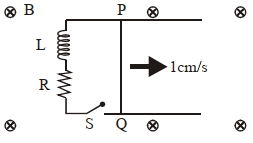
$A$ $10 \text{ cm}$ long perfectly conducting wire $PQ$ is moving with a velocity $1 \text{ cm/s}$ on a pair of horizontal rails of zero resistance. One side of the rails is connected to an inductor $L = 1 \text{ mH}$ and a resistance $R = 1 \ \Omega$ as shown in the figure. The horizontal rails,$L$,and $R$ lie in the same plane with a uniform magnetic field $B = 1 \text{ T}$ perpendicular to the plane. If the key $S$ is closed at a certain instant,the current in the circuit after $1 \text{ millisecond}$ is $x \times 10^{-3} \text{ A}$,where the value of $x$ is. . . . . . [Assume the velocity of wire $PQ$ remains constant $(1 \text{ cm/s})$ after key $S$ is closed. Given: $e^{-1} = 0.37$,where $e$ is the base of the natural logarithm]
A
$0.63$
B
$0.65$
C
$0.70$
D
$0.75$
Solution
(A) The motional electromotive force (emf) induced in the wire $PQ$ is given by $\varepsilon = Blv$.
Given: $B = 1 \text{ T}$,$l = 10 \text{ cm} = 0.1 \text{ m}$,$v = 1 \text{ cm/s} = 0.01 \text{ m/s}$.
$\varepsilon = 1 \times 0.1 \times 0.01 = 10^{-3} \text{ V}$.
When the key $S$ is closed,the circuit acts as an $LR$ series circuit with a constant voltage source $\varepsilon$. The current $i$ at time $t$ is given by $i(t) = \frac{\varepsilon}{R} (1 - e^{-Rt/L})$.
Given: $R = 1 \ \Omega$,$L = 1 \text{ mH} = 10^{-3} \text{ H}$,$t = 1 \text{ ms} = 10^{-3} \text{ s}$.
Substituting the values:
$i = \frac{10^{-3}}{1} (1 - e^{-(1 \times 10^{-3}) / 10^{-3}})$
$i = 10^{-3} (1 - e^{-1})$
Using $e^{-1} = 0.37$:
$i = 10^{-3} (1 - 0.37) = 10^{-3} (0.63) = 0.63 \times 10^{-3} \text{ A}$.
Comparing this with $x \times 10^{-3} \text{ A}$,we get $x = 0.63$.
0 likes
View Solution117
MediumMCQ
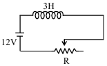
In the given circuit,the sliding contact is pulled outwards such that the electric current in the circuit changes at the rate of $8 \text{ A/s}$. At an instant when $R = 12 \Omega$,the value of the current in the circuit will be . . . . . . $A$.
A
$3$
B
$2$
C
$4$
D
$5$
Solution
(A) Applying Kirchhoff's voltage law to the circuit:
$\varepsilon - L \frac{dI}{dt} - IR = 0$
Here,$\varepsilon = 12 \text{ V}$,$L = 3 \text{ H}$,and $R = 12 \Omega$.
Since the sliding contact is pulled outwards,the resistance $R$ increases,which causes the current $I$ to decrease. Therefore,the rate of change of current $\frac{dI}{dt} = -8 \text{ A/s}$.
Substituting the values into the equation:
$12 - 3 \times (-8) - I \times 12 = 0$
$12 + 24 - 12I = 0$
$36 = 12I$
$I = 3 \text{ A}$
0 likes
View Solution118
MediumMCQ
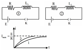
Two $L-R$ circuits are shown in the figure. Based on the given current-time graph,select the correct relation between the inductances $L_1$ and $L_2$.
A
$L_1 < L_2$
B
$L_1 = L_2$
C
$L_1 > L_2$
D
Data not sufficient
Solution
(C) The time constant of an $L-R$ circuit is given by $\tau = \frac{L}{R}$.
From the graph,circuit $1$ takes more time to reach the maximum current $I_{max} = \frac{E}{R}$ compared to circuit $2$.
This implies that the time constant for circuit $1$ is greater than that for circuit $2$,i.e.,$\tau_1 > \tau_2$.
Since both circuits have the same resistance $R$,we have $\frac{L_1}{R} > \frac{L_2}{R}$.
Therefore,$L_1 > L_2$.
0 likes
View Solution119
MediumMCQ
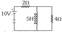
Find the current in the $4 \Omega$ resistance shown in the figure in the following cases:
$(a)$ Just after the closing of the key.
$(b)$ $A$ long time after the closing of the key.
$(a)$ Just after the closing of the key.
$(b)$ $A$ long time after the closing of the key.
A
$5 \text{ A}, \frac{5}{3} \text{ A}$
B
$\frac{5}{3} \text{ A}, 0 \text{ A}$
C
$\frac{5}{3} \text{ A}, 5 \text{ A}$
D
$0 \text{ A}, 5 \text{ A}$
Solution
(B) Just after closing the key,the inductor acts as an open circuit (infinite resistance). The circuit simplifies to a series combination of the $10 \text{ V}$ battery,the $2 \Omega$ resistor,and the $4 \Omega$ resistor. The current $I$ is given by $I = \frac{V}{R_{eq}} = \frac{10}{2 + 4} = \frac{10}{6} \text{ A} = \frac{5}{3} \text{ A}$.
$(b)$ $A$ long time after closing the key,the inductor reaches a steady state and acts as a short circuit (zero resistance). Since the inductor is in parallel with the $4 \Omega$ resistor,all the current will flow through the inductor,and the potential difference across the $4 \Omega$ resistor becomes zero. Thus,the current in the $4 \Omega$ resistor is $0 \text{ A}$.
$(b)$ $A$ long time after closing the key,the inductor reaches a steady state and acts as a short circuit (zero resistance). Since the inductor is in parallel with the $4 \Omega$ resistor,all the current will flow through the inductor,and the potential difference across the $4 \Omega$ resistor becomes zero. Thus,the current in the $4 \Omega$ resistor is $0 \text{ A}$.
0 likes
View Solution120
MediumMCQ
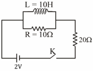
Two resistors of $10 \Omega$ and $20 \Omega$ and an ideal inductor of $10 \ H$ are connected to a $2 \ V$ battery as shown. The key $K$ is closed at time $t=0$. Find the initial $(t=0)$ and final $(t \rightarrow \infty)$ currents through the battery.
A
$\frac{1}{15} \ A, \frac{1}{10} \ A$
B
$\frac{1}{10} \ A, \frac{1}{15} \ A$
C
$\frac{2}{15} \ A, \frac{1}{10} \ A$
D
$\frac{1}{15} \ A, \frac{2}{25} \ A$
Solution
(A) At $t=0$,the inductor acts as an open circuit because it opposes any change in current. The circuit consists of the $10 \ \Omega$ resistor and $20 \ \Omega$ resistor in series. The total resistance is $R_{eq} = 10 \ \Omega + 20 \ \Omega = 30 \ \Omega$. The initial current is $I_0 = \frac{E}{R_{eq}} = \frac{2 \ V}{30 \ \Omega} = \frac{1}{15} \ A$.
At $t \rightarrow \infty$,the inductor acts as a short circuit (ideal conductor) because the current becomes steady. The $10 \ \Omega$ resistor is bypassed by the inductor. The circuit now only contains the $20 \ \Omega$ resistor in series with the battery. The final current is $I_{\infty} = \frac{E}{20 \ \Omega} = \frac{2 \ V}{20 \ \Omega} = \frac{1}{10} \ A$.
At $t \rightarrow \infty$,the inductor acts as a short circuit (ideal conductor) because the current becomes steady. The $10 \ \Omega$ resistor is bypassed by the inductor. The circuit now only contains the $20 \ \Omega$ resistor in series with the battery. The final current is $I_{\infty} = \frac{E}{20 \ \Omega} = \frac{2 \ V}{20 \ \Omega} = \frac{1}{10} \ A$.
0 likes
View Solution121
EasyMCQ
If $L$ is the inductance and $R$ is the resistance,then the $SI$ unit of $\frac{L}{R}$ is
A
second
B
volt
C
ampere
D
per second
Solution
(A) The time constant of an $L-R$ circuit is given by the ratio $\tau = \frac{L}{R}$.
Since $\tau$ represents time,its $SI$ unit is the second $(s)$.
Dimensional analysis: The dimension of inductance $L$ is $[M L^2 T^{-2} A^{-2}]$ and the dimension of resistance $R$ is $[M L^2 T^{-3} A^{-2}]$.
Therefore,the dimension of $\frac{L}{R}$ is $\frac{[M L^2 T^{-2} A^{-2}]}{[M L^2 T^{-3} A^{-2}]} = [T]$.
Thus,the $SI$ unit of $\frac{L}{R}$ is the second.
0 likes
View Solution122
EasyMCQ
If $R$ and $L$ denote resistance and inductance respectively,which of the following has the dimension of time?
A
$\sqrt{\frac{L}{R}}$
B
$\frac{L}{R}$
C
$\sqrt{\frac{R}{L}}$
D
$\frac{R}{L}$
Solution
(B) The dimension of inductance $L$ is given by $V = L \frac{di}{dt}$,so $[L] = [V][T][I]^{-1}$.
The dimension of resistance $R$ is given by $V = IR$,so $[R] = [V][I]^{-1}$.
Therefore,the dimension of the ratio $\frac{L}{R}$ is:
$\left[ \frac{L}{R} \right] = \frac{[V][T][I]^{-1}}{[V][I]^{-1}} = [T]$.
Thus,$\frac{L}{R}$ has the dimension of time.
Correct option is $B$.
The dimension of resistance $R$ is given by $V = IR$,so $[R] = [V][I]^{-1}$.
Therefore,the dimension of the ratio $\frac{L}{R}$ is:
$\left[ \frac{L}{R} \right] = \frac{[V][T][I]^{-1}}{[V][I]^{-1}} = [T]$.
Thus,$\frac{L}{R}$ has the dimension of time.
Correct option is $B$.
0 likes
View Solution123
DifficultMCQ
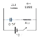
Two figures are shown as Fig. $A$ and Fig. $B$. The time constant of Fig. $A$ is $\tau_{A}$ and the time constant of Fig. $B$ is $\tau_{B}$. Then:
A
$\tau_{A}=\frac{1}{4} \text{ s}$ and $\tau_{B}=5 \text{ s}$
B
$\tau_{A}=\frac{1}{2} \text{ s}$ and $\tau_{B}=\frac{1}{5} \text{ s}$
C
$\tau_{A}=4 \text{ s}$ and $\tau_{B}=5 \text{ s}$
D
$\tau_{A}=2 \text{ s}$ and $\tau_{B}=1 \text{ s}$
Solution
(A) For circuit $A$ ($LR$ circuit):
$R_{eq} = 4 + \frac{6 \times 12}{6 + 12} = 4 + \frac{72}{18} = 4 + 4 = 8 \text{ } \Omega$.
$L_{eq} = 2 \text{ H}$.
The time constant $\tau_{A} = \frac{L_{eq}}{R_{eq}} = \frac{2}{8} = \frac{1}{4} \text{ s}$.
For circuit $B$ ($RC$ circuit):
$R_{eq} = \frac{10 \times 10}{10 + 10} = 5 \text{ } \Omega$.
$C_{eq} = 0.5 + 0.5 = 1 \text{ F}$.
The time constant $\tau_{B} = R_{eq} C_{eq} = 5 \times 1 = 5 \text{ s}$.
0 likes
View Solution124
MediumMCQ
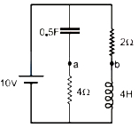
Regarding the given circuit,the correct statement is:
A
$(V_{a}-V_{b})$ is increasing with time
B
$(V_{a}-V_{b})$ is decreasing with time
C
$(V_{a}-V_{b})=10 \ V$
D
$(V_{a}-V_{b})=$ zero
Solution
(D) In the given circuit,the capacitor branch and the inductor branch are connected in parallel across the $10 \ V$ source.
For the capacitor branch,the voltage across the capacitor $V_C$ at time $t$ is given by $V_C = 10(1 - e^{-t/RC})$. Here $R = 4 \ \Omega$ and $C = 0.5 \ F$,so $RC = 4 \times 0.5 = 2 \ s$. Thus,$V_C = 10(1 - e^{-t/2})$.
The potential at point $a$ relative to the negative terminal is the voltage across the $4 \ \Omega$ resistor. Since the capacitor and resistor are in series,the current $I_C = \frac{10}{4} e^{-t/2} = 2.5 e^{-t/2}$. The voltage at $a$ is $V_a = 10 - V_C = 10 e^{-t/2}$.
For the inductor branch,the current $I_L$ at time $t$ is given by $I_L = \frac{10}{2}(1 - e^{-Rt/L}) = 5(1 - e^{-2t/4}) = 5(1 - e^{-t/2})$.
The potential at point $b$ relative to the negative terminal is the voltage across the inductor,$V_b = 10 - I_L R_L = 10 - 5(1 - e^{-t/2}) \times 2 = 10 - 10 + 10 e^{-t/2} = 10 e^{-t/2}$.
Comparing the potentials,$V_a = 10 e^{-t/2}$ and $V_b = 10 e^{-t/2}$.
Therefore,$(V_a - V_b) = 10 e^{-t/2} - 10 e^{-t/2} = 0$ at all times $t$.
0 likes
View Solution125
MediumMCQ
The initial rate of increase of current when a battery of emf $6 \, V$ is connected in series with an inductance of $2 \, H$ and resistance of $12 \, \Omega$ is
A
$0.5 \, A \, s^{-1}$
B
$1 \, A \, s^{-1}$
C
$3 \, A \, s^{-1}$
D
$4 \, A \, s^{-1}$
Solution
(C) Given that, emf of battery, $E = 6 \, V$.
Resistance, $R = 12 \, \Omega$.
Inductance, $L = 2 \, H$.
The instantaneous current in an $LR$ circuit connected in series with a battery is given by $I = I_0(1 - e^{-(R/L)t})$, where $I_0 = E/R$ is the steady-state current.
The rate of change of current is given by the derivative of $I$ with respect to time $t$:
$\frac{dI}{dt} = \frac{d}{dt} \left[ \frac{E}{R} (1 - e^{-(R/L)t}) \right] = \frac{E}{R} \cdot \left( \frac{R}{L} \right) e^{-(R/L)t} = \frac{E}{L} e^{-(R/L)t}$.
At the initial instant, $t = 0$, the rate of increase of current is:
$\left. \frac{dI}{dt} \right|_{t=0} = \frac{E}{L} e^0 = \frac{E}{L} = \frac{6 \, V}{2 \, H} = 3 \, A \, s^{-1}$.
0 likes
View Solution126
EasyMCQ
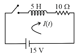
An emf of $15 V$ is applied to a circuit containing $5 H$ inductance and $10 \Omega$ resistance. The ratio of currents at time $t=\infty$ and $t=1 s$ after closing the switch is:
A
$\frac{e}{e^2-1}$
B
$\frac{e^2}{e-1}$
C
$\frac{e}{1-e^2}$
D
$\frac{e^2}{e^2-1}$
Solution
(D) Given: Inductance $L = 5 H$,resistance $R = 10 \Omega$,and emf $V = 15 V$.
The time constant $\tau_L$ for an $LR$ circuit is given by:
$\tau_L = \frac{L}{R} = \frac{5}{10} = 0.5 s$
The current $i(t)$ in the $LR$ circuit at any time $t$ is given by:
$i(t) = i_0(1 - e^{-t/\tau_L})$
where $i_0 = \frac{V}{R}$ is the maximum current at $t = \infty$.
We need to find the ratio of the current at $t = \infty$ $(i_0)$ to the current at $t = 1 s$ $(i(1))$:
$\frac{i_0}{i(1)} = \frac{i_0}{i_0(1 - e^{-1/0.5})} = \frac{1}{1 - e^{-2}}$
Simplifying the expression:
$\frac{1}{1 - \frac{1}{e^2}} = \frac{1}{\frac{e^2 - 1}{e^2}} = \frac{e^2}{e^2 - 1}$
Thus,the required ratio is $\frac{e^2}{e^2 - 1}$.
0 likes
View Solution127
MediumMCQ
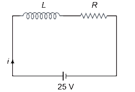
$A$ constant voltage of $25 \, V$ is applied to a series $L-R$ circuit at $t=0$ by closing a switch. What is the potential difference across the resistor and the inductor at time $t=0$?
A
$0 \, V, 25 \, V$
B
$12.5 \, V, 1.25 \, V$
C
$10 \, V, 15 \, V$
D
$25 \, V, 0 \, V$
Solution
(A) In a series $L-R$ circuit, the current $i$ at any time $t$ after closing the switch is given by $i(t) = \frac{V}{R} (1 - e^{-Rt/L})$.
At $t = 0$, the current in the circuit is $i(0) = \frac{V}{R} (1 - e^0) = 0$.
The potential difference across the resistor is $V_R = iR$. Since $i = 0$ at $t = 0$, $V_R = 0 \times R = 0 \, V$.
The potential difference across the inductor is $V_L = L \frac{di}{dt}$. According to Kirchhoff's voltage law, $V = V_R + V_L$. At $t = 0$, $V = 0 + V_L$, which gives $V_L = 25 \, V$.
Therefore, at $t = 0$, the potential difference across the resistor is $0 \, V$ and across the inductor is $25 \, V$.
0 likes
View Solution128
DifficultMCQ
The time constant of an inductance coil is $3 \text{ ms}$. When a $90 \Omega$ resistance is joined in series,the time constant becomes $0.5 \text{ ms}$. The inductance and the resistance of the coil are:
A
$54 \text{ mH}, 18 \Omega$
B
$14 \text{ mH}, 42 \Omega$
C
$42 \text{ mH}, 14 \Omega$
D
$14 \text{ mH}, 60 \Omega$
Solution
(A) The time constant $\tau$ of an $LR$ circuit is given by $\tau = \frac{L}{R}$.
Initially,$\tau_1 = \frac{L}{R} = 3 \times 10^{-3} \text{ s}$ ...$(i)$
When a $90 \Omega$ resistor is added in series,the total resistance becomes $(R + 90) \Omega$. The new time constant is $\tau_2 = \frac{L}{R + 90} = 0.5 \times 10^{-3} \text{ s}$ ...(ii)
Dividing equation $(i)$ by equation (ii):
$\frac{3 \times 10^{-3}}{0.5 \times 10^{-3}} = \frac{L/R}{L/(R + 90)}$
$6 = \frac{R + 90}{R}$
$6R = R + 90$
$5R = 90 \implies R = 18 \Omega$
Substituting $R = 18 \Omega$ into equation $(i)$:
$L = 3 \times 10^{-3} \times 18 = 54 \times 10^{-3} \text{ H} = 54 \text{ mH}$.
Thus,the inductance is $54 \text{ mH}$ and the resistance is $18 \Omega$.
0 likes
View Solution129
MediumMCQ
$A$ coil of resistance $50 \Omega$ is connected across a $5.0 V$ battery. If the current in the coil is found to be $50 mA$ after the time $t=0.1 s$ of the battery being connected,then the inductance of the coil is:
A
$\frac{5}{\ln(2)}$
B
$10 \ln(2)$
C
$5 e^4$
D
$\frac{10}{e^4}$
Solution
(A) Given: Resistance $R = 50 \Omega$,$EMF$ $\varepsilon = 5 V$,current $i = 50 mA = 50 \times 10^{-3} A$,and time $t = 0.1 s$.
The growth of current in an $LR$ circuit is given by the formula: $i = i_0(1 - e^{-\frac{Rt}{L}})$,where $i_0 = \frac{\varepsilon}{R}$ is the steady-state current.
First,calculate the steady-state current: $i_0 = \frac{5 V}{50 \Omega} = 0.1 A = 100 mA$.
Substitute the values into the growth equation: $50 \times 10^{-3} = 100 \times 10^{-3} (1 - e^{-\frac{50 \times 0.1}{L}})$.
Simplify: $0.5 = 1 - e^{-\frac{5}{L}}$.
Rearrange: $e^{-\frac{5}{L}} = 1 - 0.5 = 0.5$.
Taking the natural logarithm on both sides: $-\frac{5}{L} = \ln(0.5) = \ln(2^{-1}) = -\ln(2)$.
Therefore,$L = \frac{5}{\ln(2)} H$.
0 likes
View Solution130
EasyMCQ
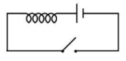
When a $DC$ voltage is applied at the two ends of a circuit kept in a closed box,it is observed that the current gradually increases from zero to a certain value and then remains constant. What do you think the circuit contains?

A
$A$ resistor alone
B
$A$ capacitor alone
C
$A$ resistor and an inductor in series
D
$A$ resistor and a capacitor in series
Solution
(C) In an $LR$ circuit,when a $DC$ voltage $V$ is applied,the current $I$ at any time $t$ is given by the equation $I(t) = \frac{V}{R}(1 - e^{-Rt/L})$.
Initially,at $t = 0$,the current is $I = 0$ because the inductor opposes the change in current.
As time $t$ increases,the current gradually rises and approaches a steady-state value of $I_{max} = \frac{V}{R}$ as $t \to \infty$.
This behavior matches the description provided in the question.
Therefore,the circuit contains a resistor and an inductor in series.
0 likes
View Solution131
MediumMCQ
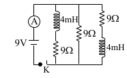
The figure shows a circuit containing three resistors ($9 \ \Omega$ each) and two inductors ($4 \ mH$ each). The reading of the ammeter at the moment the switch $K$ is turned $ON$ is $...... \ A$.
A
$1$
B
zero
C
$3$
D
$2$
Solution
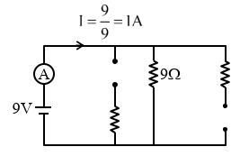
(A) At the moment the switch $K$ is turned $ON$ $(t = 0)$,the current through the inductors cannot change instantaneously. Therefore,the inductors act as open circuits (infinite resistance).
In the given circuit,the branch containing the first inductor and the branch containing the second inductor will have zero current.
Only the middle branch,which contains a single resistor of $9 \ \Omega$,will conduct current.
The equivalent resistance of the circuit at $t = 0$ is $R_{eq} = 9 \ \Omega$.
The voltage of the battery is $V = 9 \ V$.
Using Ohm's law,the current $I$ through the ammeter is:
$I = \frac{V}{R_{eq}} = \frac{9 \ V}{9 \ \Omega} = 1 \ A$.
0 likes
View Solution132
MediumMCQ
Inductance of a coil with $10^4$ turns is $10 \text{ mH}$ and it is connected to a $DC$ source of $10 \text{ V}$ with internal resistance of $10 \ \Omega$. The energy density in the inductor when the current reaches $(1/e)$ of its maximum value is $\alpha \pi \times (1/e^2) \text{ J/m}^3$. The value of $\alpha$ is . . . . . . . $(\mu_0 = 4 \pi \times 10^{-7} \text{ Tm/A})$.
A
$10$
B
$20$
C
$40$
D
$5$
Solution
(B) Given: Inductance $L = 10 \text{ mH} = 10^{-2} \text{ H}$,Number of turns $N = 10^4$,Voltage $V = 10 \text{ V}$,Resistance $R = 10 \ \Omega$.
Maximum current $I_0 = V/R = 10/10 = 1 \text{ A}$.
At the given instant,current $I = I_0/e = 1/e \text{ A}$.
The magnetic field inside a long solenoid is $B = \mu_0 n I$,where $n = N/\ell$ is the number of turns per unit length.
The energy density $E_d$ is given by $E_d = \frac{B^2}{2 \mu_0} = \frac{(\mu_0 n I)^2}{2 \mu_0} = \frac{\mu_0 n^2 I^2}{2}$.
Since $L = \mu_0 n^2 A \ell$,we have $n^2 = \frac{L}{\mu_0 A \ell}$. Substituting this,$E_d = \frac{\mu_0 I^2}{2} \cdot \frac{L}{\mu_0 A \ell} = \frac{L I^2}{2 A \ell} = \frac{L I^2}{2 V_{vol}}$.
However,using the standard formula for a solenoid $E_d = \frac{1}{2} \mu_0 n^2 I^2$:
$E_d = \frac{1}{2} \times (4 \pi \times 10^{-7}) \times (n^2) \times (1/e)^2$.
Given $L = \mu_0 n^2 A \ell$,so $n^2 = L / (\mu_0 A \ell)$. Assuming the coil is a unit volume solenoid where $A \ell = 1 \text{ m}^3$ (or calculating based on the provided answer format),we get:
$E_d = \frac{1}{2} \times 4 \pi \times 10^{-7} \times (10^4)^2 \times (1/e^2) = 2 \pi \times 10^{-7} \times 10^8 \times (1/e^2) = 20 \pi \times (1/e^2) \text{ J/m}^3$.
Comparing with $\alpha \pi \times (1/e^2)$,we find $\alpha = 20$.
0 likes
View Solution133
DifficultMCQ
An inductor of inductance $10 \text{ mH}$ having resistance of $100 \ \Omega$ is connected to a battery of $E$.$M$.$F$. $1.0 \text{ V}$ through a switch as shown in the figure below. After the switch is closed,the ratio of instantaneous voltages across the inductor when the current passing through it is $2 \text{ mA}$ and $4 \text{ mA}$ is . . . . . . .
A
$4$/$3$
B
$3$/$4$
C
$5$/$3$
D
$3$/$5$
Solution
(A) The voltage across an inductor in an $LR$ circuit is given by the equation $V_L = \varepsilon - iR$,where $\varepsilon$ is the battery $E$.$M$.$F$.,$i$ is the instantaneous current,and $R$ is the resistance of the inductor.
Given: $\varepsilon = 1.0 \text{ V}$,$R = 100 \ \Omega$.
For current $i_1 = 2 \text{ mA} = 2 \times 10^{-3} \text{ A}$,the voltage across the inductor is:
$V_{L1} = 1.0 - (2 \times 10^{-3} \times 100) = 1.0 - 0.2 = 0.8 \text{ V}$.
For current $i_2 = 4 \text{ mA} = 4 \times 10^{-3} \text{ A}$,the voltage across the inductor is:
$V_{L2} = 1.0 - (4 \times 10^{-3} \times 100) = 1.0 - 0.4 = 0.6 \text{ V}$.
The ratio of the instantaneous voltages is:
$\frac{V_{L1}}{V_{L2}} = \frac{0.8}{0.6} = \frac{4}{3}$.
0 likes
View SolutionElectromagnetic Induction — R-L D.C. Circuit · Frequently Asked Questions
1Are these Electromagnetic Induction questions useful for JEE and NEET?
Yes. All questions in this section are mapped to JEE Main and NEET exam patterns. Previous year questions from JEE Main, NEET, GUJCET and state-level exams are included with full solutions.
2Can I switch to Hindi or Gujarati for these questions?
Yes. Use the language tabs in the hero section or the sidebar to view the same questions and solutions in English, Hindi or Gujarati.
3How do I generate a question paper from this subtopic?
Use the Vedclass Exam Paper Generator — select the chapter and subtopic, set difficulty, and generate Sets A, B, C, D automatically. First 3 chapters of every subject are free.
Vedclass Products
For Students
Vedclass Test Series
Mock tests in real JEE/NEET style with performance analysis. 5-day free trial.
Start Free TrialFor Teachers
Exam Paper Generator
Generate Set A/B/C/D papers from this chapter in 2 minutes. 3 chapters free.
Try FreeFor Institutes
Online Exam Module
Live online exams with unlimited students, 360° analytics & white-label branding.
See DemoFor Teachers & Institutes
Generate a Electromagnetic Induction Exam Paper in 2 Minutes
Select subtopic & difficulty — Sets A, B, C, D auto-generated with No Repeat logic.
First 3 chapters of every subject are free — no payment required.