
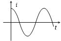
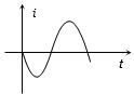
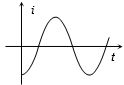
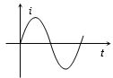
The voltage across a pure inductor is represented by the following diagram. Which one of the following diagrams will represent the current?
- A
- B
- C
- D
Explore More
Similar Questions
An alternating $emf$ $E = 440 \sin(100 \pi t)$ is applied to a circuit containing an inductance of $\frac{\sqrt{2}}{\pi} \text{ H}$. If an $AC$ ammeter is connected in the circuit,its reading will be $....... \text{ A}$.
DifficultJEE MAIN 2022
View SolutionIn a circuit consisting of a capacitance and a generator with alternating emf $E_{g}=E_{g0} \sin \omega t$,$V_{C}$ and $I_{C}$ are the voltage and current. The correct phasor diagram for such a circuit is:
An alternating voltage $v = 200 \sqrt{2} \sin(100 t)$ is connected to a $1 \mu F$ capacitor through an $A.C.$ ammeter. The reading of the ammeter shall be: (in $\text{ mA}$)
$A$ $60\; \mu F$ capacitor is connected to a $110\; V, 60\; Hz$ $ac$ supply. Determine the $rms$ value of the current in the circuit. (in $; A$)
Medium
View SolutionIn a pure inductive circuit or in an $ac$ circuit containing inductance only,the current
Easy
View SolutionVedclass Products
For Students
Vedclass Test Series
Mock tests in real JEE/NEET style with performance analysis. 5-day free trial.
Start Free TrialFor Teachers
Exam Paper Generator
Generate Set A/B/C/D exam papers from 7.5L+ questions in 2 minutes. 3 chapters free.
Try FreeFor Institutes
Online Exam Module
Live online exams with unlimited students, 360° analytics & white-label branding.
See Demo