
A English
Half Power Frequency , Quality Factor ,Resonance in AC Circuit Questions in English
Class 12 Physics · Alternating Current · Half Power Frequency , Quality Factor ,Resonance in AC Circuit
261+
Questions
English
Language
100%
With Solutions
Showing 49 of 261 questions in English
201
MediumMCQ
The resonant frequency of an $L-C$ circuit is
A
$\frac{1}{2 \pi \sqrt{L C}}$
B
$\frac{1}{2 \pi} \sqrt{\frac{L}{C}}$
C
$\frac{1}{2 \pi} \sqrt{\frac{C}{L}}$
D
$\frac{1}{\sqrt{L C}}$
Solution
(A) In an $L-C$ circuit,resonance occurs when the inductive reactance $(X_L)$ equals the capacitive reactance $(X_C)$.
$X_L = X_C$
$\omega L = \frac{1}{\omega C}$
$\omega^2 = \frac{1}{LC}$
$\omega = \frac{1}{\sqrt{LC}}$
Since $\omega = 2 \pi f$,the resonant frequency $f$ is given by:
$f = \frac{1}{2 \pi \sqrt{LC}}$
$X_L = X_C$
$\omega L = \frac{1}{\omega C}$
$\omega^2 = \frac{1}{LC}$
$\omega = \frac{1}{\sqrt{LC}}$
Since $\omega = 2 \pi f$,the resonant frequency $f$ is given by:
$f = \frac{1}{2 \pi \sqrt{LC}}$
0 likes
View Solution202
EasyMCQ
In an $L-C-R$ circuit,the power factor at resonance is
A
less than one
B
greater than one
C
unity
D
cannot be predicted
Solution
(C) In an $L-C-R$ series circuit,resonance occurs when the inductive reactance $(X_L)$ equals the capacitive reactance $(X_C)$,i.e.,$X_L = X_C$.
The impedance of the circuit is given by $Z = \sqrt{R^2 + (X_L - X_C)^2}$.
At resonance,$Z = \sqrt{R^2 + 0} = R$.
The power factor $(\cos \phi)$ is defined as the ratio of resistance to impedance: $\cos \phi = \frac{R}{Z}$.
Substituting $Z = R$,we get $\cos \phi = \frac{R}{R} = 1$.
Therefore,the power factor at resonance is unity.
0 likes
View Solution203
DifficultMCQ
What is the value of inductance $L$ for which the current is a maximum in a series $LCR$ circuit with $C=10 \mu F$ and $\omega=1000 \ s^{-1}$?
A
$100 \ mH$
B
$1 \ mH$
C
Cannot be calculated unless $R$ is known
D
$10 \ mH$
Solution
(A) The current in an $LCR$ series circuit is given by $i = \frac{V}{\sqrt{R^2 + (X_L - X_C)^2}}$,where $V$ is the $rms$ voltage,$R$ is the resistance,$X_L = \omega L$ is the inductive reactance,and $X_C = \frac{1}{\omega C}$ is the capacitive reactance.
For the current to be maximum,the impedance must be minimum,which occurs when $X_L = X_C$.
This condition is known as resonance,where $\omega L = \frac{1}{\omega C}$.
Rearranging for $L$,we get $L = \frac{1}{\omega^2 C}$.
Given $\omega = 1000 \ s^{-1}$ and $C = 10 \ \mu F = 10 \times 10^{-6} \ F$.
Substituting these values: $L = \frac{1}{(1000)^2 \times 10 \times 10^{-6}} = \frac{1}{10^6 \times 10^{-5}} = \frac{1}{10} = 0.1 \ H$.
Converting to millihenry: $0.1 \ H = 100 \ mH$.
0 likes
View Solution204
EasyMCQ
In an $LCR$ resonant circuit,the phase difference between the current and the voltage is:
A
$\frac{\pi}{4}$
B
$\frac{\pi}{2}$
C
$-\frac{\pi}{2}$
D
zero
Solution
(D) In an $LCR$ series circuit,the impedance $Z$ is given by $Z = \sqrt{R^2 + (X_L - X_C)^2}$.
At resonance,the inductive reactance $X_L$ equals the capacitive reactance $X_C$,i.e.,$X_L = X_C$.
Therefore,the net reactance $X = X_L - X_C = 0$.
The phase angle $\phi$ is given by $\tan \phi = \frac{X_L - X_C}{R} = \frac{0}{R} = 0$.
Thus,$\phi = 0$,which means the current and voltage are in the same phase at resonance.
0 likes
View Solution205
DifficultMCQ
An inductor of $0.5 \ mH$,a capacitor of $20 \ \mu F$ and a resistance of $20 \ \Omega$ are connected in series with a $220 \ V$ a.c. source. If the current is in phase with the e.m.f.,the maximum current in the circuit is $\sqrt{x} \ A$. The value of '$x$' is
A
$44$
B
$82$
C
$146$
D
$242$
Solution
(D) When the current is in phase with the voltage,the circuit is in resonance. In this condition,the inductive reactance equals the capacitive reactance,and the impedance $Z$ of the circuit is equal to the resistance $R$.
Given $R = 20 \ \Omega$.
Therefore,$Z = R = 20 \ \Omega$.
The given voltage $V_{rms} = 220 \ V$. The peak voltage $e_0$ is given by $e_0 = V_{rms} \sqrt{2} = 220 \sqrt{2} \ V$.
The maximum current $i_0$ is given by $i_0 = \frac{e_0}{Z} = \frac{220 \sqrt{2}}{20} = 11 \sqrt{2} \ A$.
We can write $11 \sqrt{2} = \sqrt{11^2 \times 2} = \sqrt{121 \times 2} = \sqrt{242} \ A$.
Comparing this with $\sqrt{x} \ A$,we get $x = 242$.
0 likes
View Solution206
DifficultMCQ
$A$ parallel combination of a pure inductor and a capacitor is connected across a source of alternating e.m.f. '$e$'. The currents flowing through the inductor and the capacitor are $i_{L}$ and $i_{C}$ respectively. In this parallel resonant circuit,the condition for the currents $i$,$i_{L}$,and $i_{C}$ is ($i =$ net r.m.s. current in the circuit).
A
$i = 0, i_{L} = i_{C} \neq 0$
B
$i \neq 0, i_{L} = i_{C} = 0$
C
$i = i_{L} = i_{C}$
D
$i = 0, i_{L} \neq i_{C}$
Solution
(A) In a parallel resonant circuit,the capacitive reactance $(X_{C})$ and inductive reactance $(X_{L})$ are equal $(X_{L} = X_{C})$.
Since the inductor and capacitor are in parallel,the voltage across them is the same.
Therefore,the magnitudes of the currents are equal: $i_{L} = i_{C} = \frac{e}{X_{L}} = \frac{e}{X_{C}}$.
However,the current through the inductor lags the voltage by $90^{\circ}$,and the current through the capacitor leads the voltage by $90^{\circ}$.
Thus,the currents $i_{L}$ and $i_{C}$ are $180^{\circ}$ out of phase with each other.
The net current $i$ in the circuit is the phasor sum of $i_{L}$ and $i_{C}$,which is $i = |i_{L} - i_{C}| = 0$.
Hence,the condition is $i = 0$ and $i_{L} = i_{C} \neq 0$.
0 likes
View Solution207
MediumMCQ
Out of the following graphs,which graph shows the correct relation (graphical representation) for an $LC$ parallel resonant circuit?
A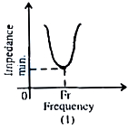
B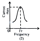
C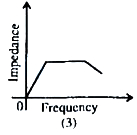
D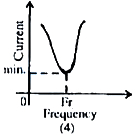
Solution
(D) In an $LC$ parallel resonant circuit,the impedance is maximum at the resonant frequency $f_r$,and the current is minimum at the resonant frequency $f_r$.
Graph $(4)$ shows that the current is minimum at the resonant frequency $f_r$,which is the correct characteristic for an $LC$ parallel resonant circuit.
Graph $(4)$ shows that the current is minimum at the resonant frequency $f_r$,which is the correct characteristic for an $LC$ parallel resonant circuit.
0 likes
View Solution208
EasyMCQ
The $LC$ parallel resonant circuit:
A
has a very high impedance
B
has a very high current
C
acts as resistance of very low value
D
has zero impedance
Solution
(A) In an $LC$ parallel resonant circuit,at resonance,the inductive reactance $(X_L)$ is equal to the capacitive reactance $(X_C)$.
This leads to a condition where the total impedance of the circuit becomes very high (theoretically infinite in an ideal circuit).
Because the impedance is very high,the current drawn from the source is minimal.
Therefore,the $LC$ parallel resonant circuit acts as a high-impedance circuit at resonance.
0 likes
View Solution209
MediumMCQ
In an electrical circuit,$R$,$L$,$C$,and an $a.c.$ voltage source are all connected in series. When $L$ is removed from the circuit,the phase difference between the voltage and the current in the circuit is $\frac{\pi}{3}$. If instead $C$ is removed from the circuit,the phase difference is again $\frac{\pi}{3}$. The power factor of the circuit is $(\tan \frac{\pi}{3} = \sqrt{3})$.
A
$\frac{\sqrt{3}}{2}$
B
$\frac{1}{2}$
C
$\frac{1}{\sqrt{2}}$
D
$1$
Solution
(D) In an $R-L-C$ series circuit,the phase difference $\phi$ is given by $\tan \phi = \frac{|X_L - X_C|}{R}$.
When $L$ is removed,the circuit becomes an $R-C$ circuit. The phase difference is $\tan \phi = \frac{X_C}{R} = \tan \frac{\pi}{3} = \sqrt{3}$. Thus,$X_C = \sqrt{3}R$.
When $C$ is removed,the circuit becomes an $R-L$ circuit. The phase difference is $\tan \phi = \frac{X_L}{R} = \tan \frac{\pi}{3} = \sqrt{3}$. Thus,$X_L = \sqrt{3}R$.
Since $X_L = X_C$,the circuit is in resonance.
At resonance,the impedance $Z = R$,and the phase difference $\phi = 0$.
The power factor is $\cos \phi = \cos 0 = 1$.
0 likes
View Solution210
DifficultMCQ
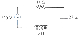
In the circuit shown,the ratio of the quality factor to the bandwidth is: (in $\text{ s}$)
A
$10$
B
$8$
C
$6$
D
$4$
Solution
(A) Given: Resistance $R = 10 \ \Omega$,Inductance $L = 3 \text{ H}$,Capacitance $C = 27 \ \mu\text{F} = 27 \times 10^{-6} \text{ F}$.
Bandwidth $(\Delta \omega) = \frac{R}{L} = \frac{10}{3} \text{ rad/s}$.
Quality factor $(Q) = \frac{1}{R} \sqrt{\frac{L}{C}} = \frac{1}{10} \sqrt{\frac{3}{27 \times 10^{-6}}} = \frac{1}{10} \sqrt{\frac{1}{9 \times 10^{-6}}} = \frac{1}{10} \times \frac{1}{3 \times 10^{-3}} = \frac{100}{3}$.
Ratio of Quality factor to Bandwidth = $\frac{Q}{\Delta \omega} = \frac{100/3}{10/3} = 10 \text{ s}$.
0 likes
View Solution211
MediumMCQ
The $Q$-factor of a resonant circuit is equal to
A
$\frac{1}{L} \sqrt{\frac{R}{C}}$
B
$\frac{1}{R} \sqrt{\frac{L}{C}}$
C
$\frac{1}{R L} \sqrt{C}$
D
$\frac{1}{C} \sqrt{\frac{R}{L}}$
Solution
(B) The quality factor ($Q$-factor) of a resonant circuit is defined as the ratio of resonant frequency to the bandwidth of the circuit.
Mathematically,$Q = \frac{\omega_{0} L}{R}$.
At resonance,the angular frequency is given by $\omega_{0} = \frac{1}{\sqrt{LC}}$.
Substituting the value of $\omega_{0}$ into the $Q$-factor formula:
$Q = \frac{1}{\sqrt{LC}} \cdot \frac{L}{R} = \frac{1}{R} \cdot \frac{\sqrt{L}}{\sqrt{C}} = \frac{1}{R} \sqrt{\frac{L}{C}}$.
0 likes
View Solution212
MediumMCQ
$A$ resistor of $50 \Omega$,an inductor of self-inductance $\left(\frac{3}{\pi^2}\right) H$,and a capacitor of unknown capacity are connected in series to an a.c. source of $100 \ V$ and $50 \ Hz$. When the voltage and current are in phase,the value of capacitance is (nearly):
A
$0.66 \times 10^{-4} \ F$
B
$0.33 \times 10^{-4} \ F$
C
$0.66 \times 10^{-2} \ F$
D
$0.33 \times 10^{-2} \ F$
Solution
(B) Given: $L = \frac{3}{\pi^2} \ H$ and $f = 50 \ Hz$.
Since the voltage and current are in phase,the circuit is in resonance.
At resonance,the inductive reactance equals the capacitive reactance,so $X_C = X_L$.
$\frac{1}{\omega C} = \omega L \implies C = \frac{1}{\omega^2 L} = \frac{1}{(2\pi f)^2 L} = \frac{1}{4\pi^2 f^2 L}$.
Substituting the values:
$C = \frac{1}{4 \pi^2 \times (50)^2 \times \frac{3}{\pi^2}} = \frac{1}{4 \times 2500 \times 3} = \frac{1}{30000} \ F$.
$C = \frac{1}{3} \times 10^{-4} \ F \approx 0.33 \times 10^{-4} \ F$.
0 likes
View Solution213
EasyMCQ
In an $LCR$ series $AC$ circuit at resonance,the value of the power factor will be . . . . . . .
A
$0$
B
$1$
C
$-1$
D
$\infty$
Solution
(B) The impedance $Z$ of an $LCR$ series circuit is given by $Z = \sqrt{R^2 + (X_C - X_L)^2}$.
At resonance,the inductive reactance $X_L$ is equal to the capacitive reactance $X_C$,i.e.,$X_L = X_C$.
Substituting this into the impedance formula,we get $Z = \sqrt{R^2 + 0} = R$.
The power factor is defined as $\cos \phi = \frac{R}{Z}$.
Substituting $Z = R$,we get $\cos \phi = \frac{R}{R} = 1$.
Therefore,the power factor at resonance is $1$.
0 likes
View Solution214
EasyMCQ
For a series $LCR$ circuit with $L=2 \ H, C=18 \ \mu F$ and $R=10 \ \Omega$. What is the value of the $Q$ factor of this circuit?
A
$55.55$
B
$44.44$
C
$22.22$
D
$33.33$
Solution
(D) The $Q$ factor of a series $LCR$ circuit is given by the formula:
$Q = \frac{1}{R} \sqrt{\frac{L}{C}}$
Given values are $L = 2 \ H$,$C = 18 \ \mu F = 18 \times 10^{-6} \ F$,and $R = 10 \ \Omega$.
Substituting these values into the formula:
$Q = \frac{1}{10} \sqrt{\frac{2}{18 \times 10^{-6}}}$
$Q = \frac{1}{10} \sqrt{\frac{1}{9 \times 10^{-6}}}$
$Q = \frac{1}{10} \times \frac{1}{3 \times 10^{-3}}$
$Q = \frac{1}{10} \times \frac{1000}{3}$
$Q = \frac{100}{3} \approx 33.33$
Therefore,the correct option is $D$.
0 likes
View Solution215
EasyMCQ
For an $LCR$ series $AC$ circuit, $L = 25 \, mH$, $R = 3 \, \Omega$, and $C = 62.5 \, \mu F$. What is the frequency of the source at which resonance occurs (in $Hz$)?
A
$35.40$
B
$100$
C
$127.39$
D
$21$
Solution
(C) The resonance frequency $v_{0}$ for an $LCR$ series circuit is given by the formula:
$v_{0} = \frac{1}{2 \pi \sqrt{LC}}$
Given values are $L = 25 \times 10^{-3} \, H$, $C = 62.5 \times 10^{-6} \, F$.
Substituting these values into the formula:
$v_{0} = \frac{1}{2 \times 3.14159 \times \sqrt{25 \times 10^{-3} \times 62.5 \times 10^{-6}}}$
$v_{0} = \frac{1}{2 \times 3.14159 \times \sqrt{1562.5 \times 10^{-9}}}$
$v_{0} = \frac{1}{2 \times 3.14159 \times \sqrt{1.5625 \times 10^{-6}}}$
$v_{0} = \frac{1}{2 \times 3.14159 \times 1.25 \times 10^{-3}}$
$v_{0} = \frac{1}{7.85398 \times 10^{-3}}$
$v_{0} \approx 127.39 \, Hz$
Thus, the correct option is $C$.
0 likes
View Solution216
EasyMCQ
$A$ sinusoidal voltage having a maximum value of $283 \ V$ and a frequency of $50 \ Hz$ is applied to an $LCR$ series circuit where $R = 3 \ \Omega$,$L = 25.48 \ mH$,and $C = 796 \ \mu F$. What is the impedance at resonance condition (in $Omega$)?
A
$4$
B
$5$
C
$3$
D
$15$
Solution
(C) At resonance condition,the inductive reactance $(X_L)$ is equal to the capacitive reactance $(X_C)$.
Therefore,the net reactance $X = X_L - X_C = 0$.
The impedance $Z$ of an $LCR$ series circuit is given by $Z = \sqrt{R^2 + (X_L - X_C)^2}$.
Substituting the resonance condition $X_L = X_C$,we get $Z = \sqrt{R^2 + 0^2} = R$.
Given $R = 3 \ \Omega$,the impedance at resonance is $Z = 3 \ \Omega$.
Therefore,the net reactance $X = X_L - X_C = 0$.
The impedance $Z$ of an $LCR$ series circuit is given by $Z = \sqrt{R^2 + (X_L - X_C)^2}$.
Substituting the resonance condition $X_L = X_C$,we get $Z = \sqrt{R^2 + 0^2} = R$.
Given $R = 3 \ \Omega$,the impedance at resonance is $Z = 3 \ \Omega$.
0 likes
View Solution217
EasyMCQ
In an $L-C-R$ series $AC$ circuit,$L = 9 \ H$,$R = 10 \ \Omega$,and $C = 100 \ \mu F$. The $Q$-factor of the circuit is . . . . . . .
A
$35$
B
$25$
C
$45$
D
$30$
Solution
(D) The $Q$-factor (Quality factor) of an $L-C-R$ series circuit is given by the formula:
$Q = \frac{1}{R} \sqrt{\frac{L}{C}}$
Given values:
$L = 9 \ H$
$R = 10 \ \Omega$
$C = 100 \ \mu F = 100 \times 10^{-6} \ F = 10^{-4} \ F$
Substituting these values into the formula:
$Q = \frac{1}{10} \sqrt{\frac{9}{10^{-4}}}$
$Q = \frac{1}{10} \times \frac{3}{10^{-2}}$
$Q = \frac{1}{10} \times 300$
$Q = 30$
Therefore,the correct option is $D$.
0 likes
View Solution218
EasyMCQ
For an $L-C-R$ $AC$ circuit,the resonance frequency is $5000 \ Hz$ and the frequencies at half-power points are $4950 \ Hz$ and $5050 \ Hz$. What will be the $Q$-factor?
A
$100$
B
$0.02$
C
$50$
D
$0.01$
Solution
(C) The $Q$-factor (Quality factor) of an $L-C-R$ circuit is defined as the ratio of the resonant frequency to the bandwidth.
$Q = \frac{f_0}{f_2 - f_1}$
Given:
Resonant frequency $f_0 = 5000 \ Hz$
Half-power frequencies $f_1 = 4950 \ Hz$ and $f_2 = 5050 \ Hz$
Bandwidth $\Delta f = f_2 - f_1 = 5050 \ Hz - 4950 \ Hz = 100 \ Hz$
Substituting the values:
$Q = \frac{5000}{100} = 50$
Therefore,the $Q$-factor is $50$.
$Q = \frac{f_0}{f_2 - f_1}$
Given:
Resonant frequency $f_0 = 5000 \ Hz$
Half-power frequencies $f_1 = 4950 \ Hz$ and $f_2 = 5050 \ Hz$
Bandwidth $\Delta f = f_2 - f_1 = 5050 \ Hz - 4950 \ Hz = 100 \ Hz$
Substituting the values:
$Q = \frac{5000}{100} = 50$
Therefore,the $Q$-factor is $50$.
0 likes
View Solution219
EasyMCQ
$A$ resistor of $R=6 \Omega$,an inductor of $L=1 \text{ H}$,and a capacitor of $C=17.36 \mu \text{F}$ are connected in series with an $AC$ source. Find the $Q$ factor.
A
$2.37$
B
$80$
C
$3.72$
D
$40$
Solution
(D) The $Q$ factor (Quality factor) of a series $LCR$ circuit is given by the formula:
$Q = \frac{1}{R} \sqrt{\frac{L}{C}}$
Given values are $R = 6 \Omega$,$L = 1 \text{ H}$,and $C = 17.36 \times 10^{-6} \text{ F}$.
Substituting these values into the formula:
$Q = \frac{1}{6} \sqrt{\frac{1}{17.36 \times 10^{-6}}}$
$Q = \frac{1}{6} \sqrt{\frac{10^6}{17.36}}$
$Q = \frac{1}{6} \times \sqrt{57603.68}$
$Q \approx \frac{1}{6} \times 240$
$Q \approx 40$
Therefore,the correct option is $D$.
0 likes
View Solution220
EasyMCQ
In a series resonant circuit, the $AC$ voltages across resistance $R$, inductor $L$, and capacitor $C$ are $5 \,V$, $10 \,V$, and $10 \,V$ respectively. The $AC$ voltage applied to the circuit will be . . . . . . . (in $V$)
A
$25$
B
$20$
C
$10$
D
$5$
Solution
(D) In a series $LCR$ circuit, the total applied voltage $V$ is given by the phasor sum of the individual voltages across the components:
$V = \sqrt{V_R^2 + (V_L - V_C)^2}$
Given values are $V_R = 5 \,V$, $V_L = 10 \,V$, and $V_C = 10 \,V$.
Substituting these values into the formula:
$V = \sqrt{5^2 + (10 - 10)^2}$
$V = \sqrt{25 + 0^2}$
$V = \sqrt{25}$
$V = 5 \,V$
Therefore, the applied $AC$ voltage is $5 \,V$.
$V = \sqrt{V_R^2 + (V_L - V_C)^2}$
Given values are $V_R = 5 \,V$, $V_L = 10 \,V$, and $V_C = 10 \,V$.
Substituting these values into the formula:
$V = \sqrt{5^2 + (10 - 10)^2}$
$V = \sqrt{25 + 0^2}$
$V = \sqrt{25}$
$V = 5 \,V$
Therefore, the applied $AC$ voltage is $5 \,V$.
0 likes
View Solution221
EasyMCQ
The resonance frequency of an $L-C-R$ $AC$ circuit is $\nu_{0}$. If the capacitance is made $4$ times its initial value,then the new resonance frequency will become . . . . . . .
A
$\frac{\nu_{0}}{4}$
B
$2 \nu_{0}$
C
$\nu_{0}$
D
$\frac{\nu_{0}}{2}$
Solution
(D) The resonance frequency of an $L-C-R$ circuit is given by the formula:
$\nu_{0} = \frac{1}{2 \pi \sqrt{LC}}$
From this formula,we can see that the resonance frequency is inversely proportional to the square root of the capacitance $C$:
$\nu_{0} \propto \frac{1}{\sqrt{C}}$
Let the initial frequency be $\nu_{0}$ with capacitance $C$,and the new frequency be $\nu_{0}'$ with capacitance $C' = 4C$.
Taking the ratio of the two frequencies:
$\frac{\nu_{0}}{\nu_{0}'} = \sqrt{\frac{C'}{C}}$
Substituting $C' = 4C$ into the equation:
$\frac{\nu_{0}}{\nu_{0}'} = \sqrt{\frac{4C}{C}} = \sqrt{4} = 2$
Therefore,the new resonance frequency is:
$\nu_{0}' = \frac{\nu_{0}}{2}$
0 likes
View Solution222
EasyMCQ
$A$ $L-C-R$ series $AC$ circuit is tuned to resonance. The impedance of the circuit is now . . . . . . .
A
$R$
B
$\left[R^{2}+\left(\frac{1}{\omega C}-\omega L\right)^{2}\right]^{\frac{1}{2}}$
C
$\left[R^{2}+(\omega L)^{2}+\left(\frac{1}{\omega C}\right)^{2}\right]^{\frac{1}{2}}$
D
$\left[R^{2}+\left(\omega L-\frac{1}{\omega C}\right)^{2}\right]^{\frac{1}{2}}$
Solution
(A) In an $L-C-R$ series $AC$ circuit,the impedance $Z$ is given by the formula: $Z = \sqrt{R^{2} + (X_{L} - X_{C})^{2}}$,where $X_{L} = \omega L$ and $X_{C} = \frac{1}{\omega C}$.
At resonance,the inductive reactance equals the capacitive reactance,i.e.,$X_{L} = X_{C}$ or $\omega L = \frac{1}{\omega C}$.
Substituting this into the impedance formula: $Z = \sqrt{R^{2} + (0)^{2}} = \sqrt{R^{2}} = R$.
Therefore,at resonance,the impedance of the circuit is equal to the resistance $R$.
0 likes
View Solution223
EasyMCQ
In an $L-C-R$ series circuit,the value of only capacitance $C$ is varied. The resulting variation of resonance frequency $f_0$ as a function of $C$ can be represented as
A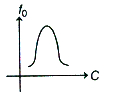
B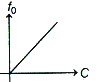
C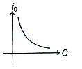
D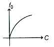
Solution
(C) The resonance frequency $f_0$ in an $L-C-R$ series circuit is given by the formula:
$f_0 = \frac{1}{2 \pi \sqrt{L C}}$
From this expression,we can see that the resonance frequency is inversely proportional to the square root of the capacitance:
$f_0 \propto \frac{1}{\sqrt{C}}$
As the value of capacitance $C$ increases,the resonance frequency $f_0$ decreases. This relationship represents a hyperbolic curve,which corresponds to the graph shown in option $C$.
0 likes
View Solution224
EasyMCQ
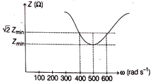
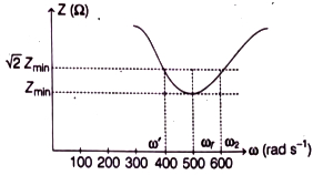
The total impedance of a series $L-C-R$ circuit varies with the angular frequency of the $AC$ source connected to it,as shown in the graph. The quality factor $Q$ of the series $L-C-R$ circuit is:
A
$0.4$
B
$2.5$
C
$5$
D
$1$
Solution
(B) From the given graph,we can identify the resonant angular frequency $\omega_r$ and the half-power frequencies $\omega_1$ and $\omega_2$ where the impedance $Z = \sqrt{2} Z_{\text{min}}$.
$1$. The resonant frequency is $\omega_r = 500 \text{ rad/s}$.
$2$. The lower half-power frequency is $\omega_1 = 400 \text{ rad/s}$.
$3$. The upper half-power frequency is $\omega_2 = 600 \text{ rad/s}$.
The quality factor $Q$ is defined as the ratio of the resonant frequency to the bandwidth:
$Q = \frac{\omega_r}{\omega_2 - \omega_1}$
Substituting the values:
$Q = \frac{500}{600 - 400}$
$Q = \frac{500}{200}$
$Q = 2.5$
0 likes
View Solution225
EasyMCQ
In a series $LCR$ circuit at resonance,the phase difference between voltage and current is
A
Zero
B
$\pi$
C
$\frac{\pi}{4}$
D
$\frac{\pi}{2}$
Solution
(A) In an $L-C-R$ series resonance circuit,the inductive reactance $X_L$ is equal to the capacitive reactance $X_C$.
Thus,$X_L = X_C$.
The phase difference $\phi$ is given by the formula $\tan \phi = \frac{X_L - X_C}{R}$.
Substituting $X_L = X_C$,we get $\tan \phi = \frac{0}{R} = 0$.
Therefore,$\phi = 0^{\circ}$.
Thus,$X_L = X_C$.
The phase difference $\phi$ is given by the formula $\tan \phi = \frac{X_L - X_C}{R}$.
Substituting $X_L = X_C$,we get $\tan \phi = \frac{0}{R} = 0$.
Therefore,$\phi = 0^{\circ}$.
0 likes
View Solution226
MediumMCQ
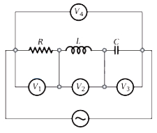
An ideal resistance $R$,ideal inductance $L$,ideal capacitance $C$,and $AC$ voltmeters $V_{1}, V_{2}, V_{3}$ and $V_{4}$ are connected to an $AC$ source as shown in the figure. At resonance,
A
reading in $V_{2} =$ reading in $V_{3}$
B
reading in $V_{3} =$ reading in $V_{1}$
C
reading in $V_{1} =$ reading in $V_{2}$
D
reading in $V_{2} =$ reading in $V_{4}$
Solution
(A) In the given circuit,$V_{1}$ measures the voltage across the resistor $R$,$V_{2}$ measures the voltage across the inductor $L$,and $V_{3}$ measures the voltage across the capacitor $C$.
At resonance,the inductive reactance $X_{L}$ is equal to the capacitive reactance $X_{C}$ $(X_{L} = X_{C})$.
Since the same current $I$ flows through the series combination of $R, L,$ and $C$,the voltage across the inductor is $V_{L} = I X_{L}$ and the voltage across the capacitor is $V_{C} = I X_{C}$.
Therefore,at resonance,$V_{L} = V_{C}$.
Since $V_{2}$ measures $V_{L}$ and $V_{3}$ measures $V_{C}$,the readings of $V_{2}$ and $V_{3}$ are equal.
0 likes
View Solution227
MediumMCQ
In a series resonant $R-L-C$ circuit, the voltage across $R$ is $100 \, V$ and the value of $R = 1000 \, \Omega$. The capacitance of the capacitor is $2 \times 10^{-6} \, F$; the angular frequency of the $AC$ source is $200 \, rad \, s^{-1}$. Then the potential difference across the inductance coil is: (in $V$)
A
$100$
B
$40$
C
$250$
D
$400$
Solution
(C) The current $i$ in the series $R-L-C$ circuit is given by $i = \frac{V_R}{R}$.
Substituting the given values: $i = \frac{100 \, V}{1000 \, \Omega} = 0.1 \, A$.
At resonance, the inductive reactance $X_L$ is equal to the capacitive reactance $X_C$, and the potential difference across the inductor $V_L$ is equal to the potential difference across the capacitor $V_C$.
The potential difference across the capacitor is $V_C = i X_C = i \left( \frac{1}{\omega C} \right)$.
Substituting the values: $V_C = 0.1 \times \left( \frac{1}{200 \times 2 \times 10^{-6}} \right)$.
$V_C = 0.1 \times \left( \frac{1}{400 \times 10^{-6}} \right) = 0.1 \times \left( \frac{10^6}{400} \right) = 0.1 \times 2500 = 250 \, V$.
Since $V_L = V_C$ at resonance, the potential difference across the inductance coil is $250 \, V$.
0 likes
View Solution228
DifficultMCQ
For a series $LCR$ circuit at resonance,the statement which is not true is:
A
Peak energy stored by a capacitor = peak energy stored by an inductor.
B
Average power = apparent power.
C
Wattless current is zero.
D
Power factor is zero.
Solution
(D) In a series $LCR$ circuit at resonance,the inductive reactance $X_L$ is equal to the capacitive reactance $X_C$ $(X_L = X_C)$.
At resonance,the phase difference $\phi$ between voltage and current is $0^{\circ}$.
$1$. The power factor is $\cos \phi = \cos 0^{\circ} = 1$. Thus,option $D$ is incorrect.
$2$. Average power $P_{avg} = V_{rms} I_{rms} \cos \phi = V_{rms} I_{rms} (1) = V_{rms} I_{rms}$,which is equal to the apparent power. Thus,option $B$ is true.
$3$. Peak energy stored in the capacitor is $\frac{1}{2} C V_0^2$ and in the inductor is $\frac{1}{2} L I_0^2$. At resonance,these values are equal. Thus,option $A$ is true.
$4$. Wattless current is $I_{rms} \sin \phi$. Since $\phi = 0^{\circ}$,$\sin 0^{\circ} = 0$,so wattless current is zero. Thus,option $C$ is true.
Therefore,the statement that is not true is that the power factor is zero.
0 likes
View Solution229
EasyMCQ
Which of the following combinations should be selected for better tuning of an $L-C-R$ circuit used for communication?
A
$R=20 \Omega, L=1.5 \text{ H}, C=35 \mu\text{F}$
B
$R=25 \Omega, L=2.5 \text{ H}, C=45 \mu\text{F}$
C
$R=25 \Omega, L=1.5 \text{ H}, C=45 \mu\text{F}$
D
$R=15 \Omega, L=3.5 \text{ H}, C=30 \mu\text{F}$
Solution
(D) For better tuning of an $L-C-R$ circuit used in communication,the quality factor $Q$ must be high.
The formula for the quality factor is $Q = \frac{1}{R} \sqrt{\frac{L}{C}}$.
To maximize $Q$,we need a small resistance $R$,a large inductance $L$,and a small capacitance $C$.
Comparing the given options:
$A: R=20, L=1.5, C=35$
$B: R=25, L=2.5, C=45$
$C: R=25, L=1.5, C=45$
$D: R=15, L=3.5, C=30$
Option $D$ has the minimum resistance $(15 \Omega)$,the maximum inductance $(3.5 \text{ H})$,and the minimum capacitance $(30 \mu\text{F})$.
Therefore,the combination in option $D$ provides the highest quality factor,resulting in better tuning.
0 likes
View Solution230
DifficultMCQ
$A$ series $LCR$ circuit contains inductance $5 \ mH$,capacitance $2 \ \mu F$,and resistance $10 \ \Omega$. If the frequency of the $A.C.$ source is varied,what is the frequency at which maximum power is dissipated?
A
$ \frac{10^{5}}{\pi} \ Hz $
B
$ \frac{10^{-5}}{\pi} \ Hz $
C
$ \frac{2}{\pi} \times 10^{5} \ Hz $
D
$ \frac{5}{\pi} \times 10^{3} \ Hz $
Solution
(D) Maximum power is dissipated in an $LCR$ circuit at the resonant frequency.
Given: Inductance $L = 5 \ mH = 5 \times 10^{-3} \ H$,Capacitance $C = 2 \ \mu F = 2 \times 10^{-6} \ F$.
The resonant frequency $f_R$ is given by the formula:
$f_R = \frac{1}{2 \pi \sqrt{LC}}$
Substituting the values:
$f_R = \frac{1}{2 \pi \sqrt{5 \times 10^{-3} \times 2 \times 10^{-6}}}$
$f_R = \frac{1}{2 \pi \sqrt{10 \times 10^{-9}}} = \frac{1}{2 \pi \sqrt{10^{-8}}}$
$f_R = \frac{1}{2 \pi \times 10^{-4}}$
$f_R = \frac{10^4}{2 \pi} = \frac{10 \times 10^3}{2 \pi} = \frac{5 \times 10^3}{\pi} \ Hz$.
0 likes
View Solution231
MediumMCQ
The readings of the ammeter and voltmeter in the following circuit are respectively:
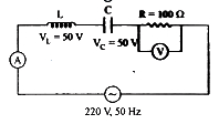
A
$ 2.7 \, A, 220 \, V $
B
$ 1.2 \, A, 120 \, V $
C
$ 2.2 \, A, 220 \, V $
D
$ 1.5 \, A, 100 \, V $
Solution
(C) In the given $ LCR $ series circuit, the voltage across the inductor is $ V_L = 50 \, V $ and the voltage across the capacitor is $ V_C = 50 \, V $.
Since $ V_L = V_C $, the circuit is in resonance.
In a resonant $ LCR $ circuit, the net reactance is zero $( X_L - X_C = 0 )$, meaning the circuit behaves as a purely resistive circuit.
Therefore, the entire source voltage drops across the resistor $ R $.
Thus, the voltmeter reading is $ V_R = V_{source} = 220 \, V $.
The current in the circuit is given by $ I = \frac{V_R}{R} = \frac{220 \, V}{100 \, \Omega} = 2.2 \, A $.
Hence, the ammeter reading is $ 2.2 \, A $ and the voltmeter reading is $ 220 \, V $.
0 likes
View Solution232
MediumMCQ
$A$ tuned amplifier circuit is used to generate a carrier frequency of $ 2 \text{ MHz} $ for amplitude modulation. The value of $ \sqrt{LC} $ is
A
$ \frac{1}{2 \pi \times 10^{6}} $
B
$ \frac{1}{2 \times 10^{6}} $
C
$ \frac{1}{3 \pi \times 10^{6}} $
D
$ \frac{1}{4 \pi \times 10^{6}} $
Solution
(D) The resonant frequency $ f $ of a tuned amplifier circuit ($LC$ circuit) is given by the formula: $ f = \frac{1}{2 \pi \sqrt{LC}} $.
Rearranging the formula to solve for $ \sqrt{LC} $,we get: $ \sqrt{LC} = \frac{1}{2 \pi f} $.
Given the carrier frequency $ f = 2 \text{ MHz} = 2 \times 10^{6} \text{ Hz} $.
Substituting the value of $ f $ into the equation: $ \sqrt{LC} = \frac{1}{2 \pi \times (2 \times 10^{6})} $.
Calculating the denominator: $ \sqrt{LC} = \frac{1}{4 \pi \times 10^{6}} $.
0 likes
View Solution233
EasyMCQ
In an $LCR$ circuit,at resonance
A
the current and voltage are in phase
B
the impedance is maximum
C
the current is minimum
D
the current leads the voltage by $\pi / 2$
Solution
(A) In an $LCR$ circuit,resonance occurs when the inductive reactance $(X_L = \omega L)$ is equal to the capacitive reactance $(X_C = 1/(\omega C))$.
At this condition,the net reactance $X = X_L - X_C = 0$.
The impedance of the circuit is given by $Z = \sqrt{R^2 + (X_L - X_C)^2}$.
At resonance,$Z = R$,which is the minimum possible impedance.
Since the net reactance is zero,the phase angle $\phi = \tan^{-1}((X_L - X_C)/R) = 0$.
Therefore,the current and voltage are in phase at resonance.
0 likes
View Solution234
MediumMCQ
For better tuning of a series $LCR$ circuit in a communication system,the preferred combination is
A
$R=20 \Omega, L=1.5 \text{ H}, C=35 \mu\text{F}$
B
$R=15 \Omega, L=3.5 \text{ H}, C=30 \mu\text{F}$
C
$R=25 \Omega, L=2.5 \text{ H}, C=45 \mu\text{F}$
D
$R=15 \Omega, L=2.5 \text{ H}, C=45 \mu\text{F}$
Solution
(B) For better tuning of a series $LCR$ circuit,the quality factor $(Q)$ should be as high as possible.
The quality factor is given by the formula: $Q = \frac{1}{R} \sqrt{\frac{L}{C}}$.
To maximize $Q$,we need a small resistance $(R)$ and a large ratio of inductance $(L)$ to capacitance $(C)$.
Let us calculate the factor $F = \frac{1}{R} \sqrt{\frac{L}{C}}$ for each option:
$A: F = \frac{1}{20} \sqrt{\frac{1.5}{35 \times 10^{-6}}} \approx 10.35$
$B: F = \frac{1}{15} \sqrt{\frac{3.5}{30 \times 10^{-6}}} \approx 22.79$
$C: F = \frac{1}{25} \sqrt{\frac{2.5}{45 \times 10^{-6}}} \approx 9.43$
$D: F = \frac{1}{15} \sqrt{\frac{2.5}{45 \times 10^{-6}}} \approx 15.71$
Comparing the values,option $B$ provides the highest quality factor,which indicates better tuning.
0 likes
View Solution235
MediumMCQ
In a series resonant $LCR$ circuit,for the power dissipated to become half of the maximum power dissipated,the current amplitude is
A
$\frac{1}{\sqrt{2}}$ times its maximum value.
B
$\frac{1}{2}$ times its maximum value.
C
twice its maximum value.
D
$\sqrt{2}$ times its maximum value.
Solution
(A) The power dissipated in an $LCR$ circuit is given by $P = I_{rms}^2 R = \frac{1}{2} I_0^2 R$,where $I_0$ is the peak current.
At resonance,the power dissipated is maximum,given by $P_{max} = \frac{1}{2} I_{max}^2 R$.
We want the power to be half of the maximum power: $P = \frac{1}{2} P_{max}$.
Substituting the expressions,we get $\frac{1}{2} I^2 R = \frac{1}{2} (\frac{1}{2} I_{max}^2 R)$.
This simplifies to $I^2 = \frac{1}{2} I_{max}^2$.
Taking the square root of both sides,we get $I = \frac{1}{\sqrt{2}} I_{max}$.
Thus,the current amplitude must be $\frac{1}{\sqrt{2}}$ times its maximum value.
0 likes
View Solution236
EasyMCQ
$A$ series $LCR$ circuit is shown in the figure. Where the inductance of $10 \ H$,capacitance $40 \ \mu F$,and resistance $60 \ \Omega$ are connected to a variable frequency $240 \ V$ source. The current at resonating frequency is (in $A$)
A
$4$
B
$2$
C
$5.4$
D
$5.8$
Solution
(A) In an $LCR$ series circuit,the given values are:
$L = 10 \ H$,$C = 40 \ \mu F$,$R = 60 \ \Omega$,and $V = 240 \ V$.
At resonance,the inductive reactance $(X_L)$ equals the capacitive reactance $(X_C)$,which means the net impedance $(Z)$ of the circuit is equal to the resistance $(R)$.
$Z = R = 60 \ \Omega$.
The current $(I)$ at resonance is given by Ohm's law:
$I = \frac{V}{Z} = \frac{240 \ V}{60 \ \Omega} = 4 \ A$.
0 likes
View Solution237
EasyMCQ
$A$ resistor of resistance $R$, an inductor of inductive reactance $2R$, and a capacitor of capacitive reactance $X_C$ are connected in series to an $A.C.$ source. If the series $LCR$ circuit is in resonance, then the power factor of the circuit and the value $X_C$ are respectively:
A
$0.5$ and $4R$
B
$1$ and $2R$
C
$0.5$ and $2R$
D
$1$ and $4R$
Solution
(B) In an $LCR$ series circuit, resonance occurs when the inductive reactance equals the capacitive reactance.
Given, inductive reactance $X_L = 2R$.
At resonance, $X_C = X_L = 2R$.
The impedance $Z$ of the circuit at resonance is equal to the resistance $R$, as $Z = \sqrt{R^2 + (X_L - X_C)^2} = \sqrt{R^2 + 0} = R$.
The power factor is defined as $\cos \phi = \frac{R}{Z}$.
Substituting the values, $\cos \phi = \frac{R}{R} = 1$.
Therefore, the power factor is $1$ and $X_C = 2R$.
0 likes
View Solution238
EasyMCQ
$A$ $50 \text{ Hz}$ $AC$ circuit has a $10 \text{ mH}$ inductor and a $2 \text{ } \Omega$ resistor in series. The value of capacitance to be placed in series in the circuit to make the circuit power factor as unity is
A
$1.014 \times 10^{-6} \text{ F}$
B
$1.014 \times 10^{-3} \text{ F}$
C
$2.6 \times 10^{-3} \text{ F}$
D
$4.125 \times 10^{-3} \text{ F}$
Solution
(B) For the power factor to be unity $(\cos \phi = 1)$,the circuit must be in resonance.
In an $LCR$ series circuit at resonance,the inductive reactance equals the capacitive reactance,i.e.,$X_L = X_C$.
This implies $\omega L = \frac{1}{\omega C}$,where $\omega = 2 \pi f$.
Substituting the values: $2 \pi f = \frac{1}{\sqrt{LC}}$.
Given $f = 50 \text{ Hz}$,$L = 10 \text{ mH} = 10 \times 10^{-3} \text{ H}$.
$2 \pi \times 50 = \frac{1}{\sqrt{10 \times 10^{-3} \times C}}$.
$100 \pi = \frac{1}{\sqrt{0.01 \times C}}$.
Squaring both sides: $(100 \pi)^2 = \frac{1}{0.01 \times C}$.
$10000 \times \pi^2 = \frac{1}{0.01 \times C}$.
$C = \frac{1}{10000 \times \pi^2 \times 0.01} = \frac{1}{100 \times \pi^2} \approx \frac{1}{100 \times 9.8696} \approx \frac{1}{986.96} \approx 1.0132 \times 10^{-3} \text{ F}$.
Thus,the required capacitance is approximately $1.014 \times 10^{-3} \text{ F}$.
0 likes
View Solution239
EasyMCQ
The frequency of $AC$ at which a $16 \mu F$ capacitor and a $\frac{10}{\pi^2} \ mH$ inductor will have the same reactance is: (in $kHz$)
A
$1$
B
$1.25$
C
$1.5$
D
$2$
Solution
(B) Given: Capacitance $C = 16 \ \mu F = 16 \times 10^{-6} \ F$.
Inductance $L = \frac{10}{\pi^2} \ mH = \frac{10}{\pi^2} \times 10^{-3} \ H$.
For the reactances to be equal,$X_L = X_C$.
Substituting the formulas for inductive and capacitive reactance: $L \omega = \frac{1}{C \omega}$.
Since $\omega = 2 \pi f$,we have $L(2 \pi f) = \frac{1}{C(2 \pi f)}$.
Rearranging for frequency $f$: $f^2 = \frac{1}{4 \pi^2 LC}$,which gives $f = \frac{1}{2 \pi \sqrt{LC}}$.
Substituting the values: $f = \frac{1}{2 \pi} \sqrt{\frac{1}{(\frac{10}{\pi^2} \times 10^{-3}) \times (16 \times 10^{-6})}}$.
$f = \frac{1}{2 \pi} \sqrt{\frac{\pi^2}{160 \times 10^{-9}}} = \frac{1}{2 \pi} \sqrt{\frac{\pi^2}{1.6 \times 10^{-7}}} = \frac{1}{2 \pi} \times \frac{\pi}{\sqrt{1.6 \times 10^{-7}}}$.
Calculating the value: $f = \frac{1}{2} \times \frac{1}{\sqrt{16 \times 10^{-8}}} = \frac{1}{2 \times 4 \times 10^{-4}} = \frac{10^4}{8} = 1250 \ Hz = 1.25 \ kHz$.
0 likes
View Solution240
EasyMCQ
$A$ resistor of $100 \Omega$, an inductor of $\frac{25}{\pi^2} \text{ mH}$ and a capacitor of $0.1 \mu\text{F}$ are connected in series to an $AC$ source. The impedance of the circuit is minimum for a frequency of (in $\text{ kHz}$)
A
$5$
B
$10$
C
$15$
D
$20$
Solution
(B) The impedance of an $LCR$ series circuit is minimum at the resonant frequency, where the inductive reactance equals the capacitive reactance $(X_L = X_C)$.
The resonant angular frequency is given by $\omega = \frac{1}{\sqrt{LC}}$.
Given: $L = \frac{25}{\pi^2} \times 10^{-3} \text{ H}$, $C = 0.1 \times 10^{-6} \text{ F}$.
Substituting the values:
$\omega = \frac{1}{\sqrt{\frac{25}{\pi^2} \times 10^{-3} \times 0.1 \times 10^{-6}}} = \frac{1}{\sqrt{\frac{2.5}{\pi^2} \times 10^{-9}}} = \frac{1}{\sqrt{\frac{25}{\pi^2} \times 10^{-10}}} = \frac{\pi}{5 \times 10^{-5}} = \frac{\pi}{5} \times 10^5 \text{ rad/s}$.
Since $\omega = 2\pi f$, we have $2\pi f = \frac{\pi}{5} \times 10^5$.
$f = \frac{10^5}{10} = 10^4 \text{ Hz} = 10 \text{ kHz}$.
0 likes
View Solution241
EasyMCQ
Resonance frequency of $L-C-R$ series $AC$ circuit is $f_0$. Now,if the inductance is reduced to $\frac{1}{4}$ times and the capacitance is increased to $16$ times,then the new resonance frequency becomes:
A
$\frac{f_0}{4}$
B
$\frac{f_0}{2}$
C
$2 f_0$
D
$4 f_0$
Solution
(B) The resonance frequency of a series $L-C-R$ circuit is given by the formula:
$f_0 = \frac{1}{2 \pi \sqrt{L C}} \quad \dots (i)$
When the inductance is reduced to $L^{\prime} = \frac{L}{4}$ and the capacitance is increased to $C^{\prime} = 16 C$,the new resonance frequency $f_0^{\prime}$ is:
$f_0^{\prime} = \frac{1}{2 \pi \sqrt{L^{\prime} C^{\prime}}}$
Substituting the new values:
$f_0^{\prime} = \frac{1}{2 \pi \sqrt{(\frac{L}{4}) \times (16 C)}}$
$f_0^{\prime} = \frac{1}{2 \pi \sqrt{4 L C}}$
$f_0^{\prime} = \frac{1}{2} \times \frac{1}{2 \pi \sqrt{L C}}$
Using equation $(i)$,we get:
$f_0^{\prime} = \frac{f_0}{2}$
0 likes
View Solution242
EasyMCQ
$A$ resonant frequency of a circuit is $f$. If the capacitance is made four times the initial value,then the resonant frequency will become
A
$f$
B
$\frac{f}{2}$
C
$\frac{f}{4}$
D
$2f$
Solution
(B) The resonant frequency of an $L-C$ circuit is given by the formula: $f = \frac{1}{2 \pi \sqrt{LC}}$.
From this relation,we can see that $f \propto \frac{1}{\sqrt{C}}$.
Let the initial frequency be $f_1 = f$ and the initial capacitance be $C_1 = C$.
Let the new frequency be $f_2$ and the new capacitance be $C_2 = 4C$.
Using the proportionality $f \propto \frac{1}{\sqrt{C}}$,we have the ratio: $\frac{f_2}{f_1} = \sqrt{\frac{C_1}{C_2}}$.
Substituting the values: $\frac{f_2}{f} = \sqrt{\frac{C}{4C}} = \sqrt{\frac{1}{4}} = \frac{1}{2}$.
Therefore,the new resonant frequency is $f_2 = \frac{f}{2}$.
0 likes
View Solution243
MediumMCQ
An $LCR$ series circuit is connected to an external $emf$,$e = 200 \sin(100 \pi t) \ V$. The values of capacitance and resistance in the circuit are $1 \ \mu F$ and $100 \ \Omega$ respectively. The amplitude of current in the circuit is maximum when the inductance is (in henry):
A
$\frac{100}{\pi^2}$
B
$100$
C
$100 \pi$
D
$10^4$
Solution
(A) In an $LCR$ series circuit,the amplitude of the current is given by $I_0 = \frac{E_0}{Z}$,where $Z = \sqrt{R^2 + (X_L - X_C)^2}$.
For the current amplitude to be maximum,the impedance $Z$ must be minimum.
This occurs at resonance,where $X_L = X_C$.
Given the $emf$ equation $e = 200 \sin(100 \pi t) \ V$,the angular frequency is $\omega = 100 \pi \ rad/s$.
The condition for resonance is $\omega L = \frac{1}{\omega C}$.
Substituting the given values: $100 \pi \times L = \frac{1}{100 \pi \times 1 \times 10^{-6}}$.
$L = \frac{1}{(100 \pi)^2 \times 10^{-6}} = \frac{1}{10000 \pi^2 \times 10^{-6}} = \frac{1}{10^{-2} \pi^2} = \frac{100}{\pi^2} \ H$.
0 likes
View Solution244
EasyMCQ
An inductor of inductance $L$,a capacitor of capacitance $C$,and a resistor of resistance $R$ are connected in series to an $ac$ source. The quality factor of the circuit is
A
$\sqrt{\frac{L}{CR^2}}$
B
$\sqrt{\frac{LR^2}{C}}$
C
$\sqrt{\frac{LC}{R^2}}$
D
$\sqrt{\frac{L^2 C}{R}}$
Solution
(A) The quality factor $(Q)$ of a series $LCR$ circuit is defined as the ratio of the resonant frequency to the bandwidth of the circuit.
Mathematically,it is given by the formula: $Q = \frac{\omega_0 L}{R}$,where $\omega_0$ is the resonant angular frequency.
For a series $LCR$ circuit,the resonant angular frequency is $\omega_0 = \frac{1}{\sqrt{LC}}$.
Substituting this value into the formula for $Q$:
$Q = \frac{1}{R} \cdot \frac{1}{\sqrt{LC}} \cdot L$
$Q = \frac{1}{R} \sqrt{\frac{L^2}{LC}}$
$Q = \frac{1}{R} \sqrt{\frac{L}{C}}$
$Q = \sqrt{\frac{L}{CR^2}}$
Therefore,the correct option is $A$.
0 likes
View Solution245
EasyMCQ
The inductance $L$,capacitance $C$,and resistance $R$ are the values of the components connected in series to an $AC$ source of angular frequency $\omega$. The inductive and capacitive reactances are $X_L$ and $X_C$ respectively. If the circuit is purely resistive,then
A
$L=C$
B
$X_L=X_C$
C
$\omega L=\omega C$
D
$R=L=C$
Solution
(B) In an $LCR$ series circuit,the total impedance $Z$ is given by $Z = \sqrt{R^2 + (X_L - X_C)^2}$.
For the circuit to be purely resistive,the net reactance must be zero,which means the inductive reactance must equal the capacitive reactance.
Therefore,$X_L - X_C = 0$,which implies $X_L = X_C$.
At this condition,the circuit is said to be in resonance,and the impedance $Z$ becomes equal to $R$.
For the circuit to be purely resistive,the net reactance must be zero,which means the inductive reactance must equal the capacitive reactance.
Therefore,$X_L - X_C = 0$,which implies $X_L = X_C$.
At this condition,the circuit is said to be in resonance,and the impedance $Z$ becomes equal to $R$.
0 likes
View Solution246
MediumMCQ
The $Q$-value of a series $LCR$ circuit with $L=2 \ H$,$C=32 \ \mu F$,and $R=20 \ \Omega$ is:
A
$12.5$
B
$25$
C
$50$
D
$125$
Solution
(A) The $Q$-factor (quality factor) of a series $LCR$ circuit is given by the formula:
$Q = \frac{1}{R} \sqrt{\frac{L}{C}}$
Given values are:
$L = 2 \ H$
$C = 32 \ \mu F = 32 \times 10^{-6} \ F$
$R = 20 \ \Omega$
Substituting these values into the formula:
$Q = \frac{1}{20} \sqrt{\frac{2}{32 \times 10^{-6}}}$
$Q = \frac{1}{20} \sqrt{\frac{1}{16 \times 10^{-6}}}$
$Q = \frac{1}{20} \times \frac{1}{4 \times 10^{-3}}$
$Q = \frac{1}{20} \times \frac{1000}{4}$
$Q = \frac{250}{20} = 12.5$
Thus,the $Q$-value is $12.5$.
0 likes
View Solution247
EasyMCQ
$A$ $L-C-R$ series circuit is connected to a source of alternating current. At resonance,the applied voltage and the current flowing through the circuit will have a phase difference of
A
$\pi$
B
$\frac{\pi}{2}$
C
$\frac{\pi}{4}$
D
$0^{\circ}$
Solution
(D) In an $L-C-R$ series circuit,the phase difference $\phi$ between the current and the voltage is given by the relation $\cos \phi = \frac{R}{Z}$,where $Z$ is the impedance of the circuit.
At resonance,the inductive reactance $X_L$ is equal to the capacitive reactance $X_C$,i.e.,$X_L = X_C$.
The impedance $Z$ of the circuit is given by $Z = \sqrt{R^2 + (X_L - X_C)^2}$.
Substituting $X_L = X_C$ into the impedance formula,we get $Z = \sqrt{R^2 + 0} = R$.
Now,substituting $Z = R$ into the phase difference formula,we get $\cos \phi = \frac{R}{R} = 1$.
Since $\cos \phi = 1$,it follows that $\phi = 0^{\circ}$.
Therefore,at resonance,the applied voltage and the current are in the same phase.
0 likes
View Solution248
EasyMCQ
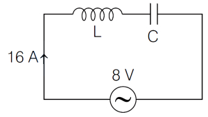
An inductor coil is connected to a capacitor and an $AC$ source of rms voltage $8 \, V$ in series. The rms current in the circuit is $16 \, A$ and is in phase with the emf. If this inductor coil is connected to a $6 \, V$ $DC$ battery, the magnitude of the steady current is (in $A$)
A
$8$
B
$10$
C
$12$
D
$16$
Solution
(C) In the $AC$ circuit, the current is in phase with the emf, which implies that the circuit is in resonance. At resonance, the impedance $Z$ of the circuit is equal to the resistance $R$ of the inductor coil $(Z = R)$.
Given, rms voltage $V_{\text{rms}} = 8 \, V$ and rms current $I_{\text{rms}} = 16 \, A$.
The resistance of the inductor coil is $R = \frac{V_{\text{rms}}}{I_{\text{rms}}} = \frac{8}{16} = 0.5 \, \Omega$.
When the inductor coil is connected to a $6 \, V$ $DC$ battery, the capacitor acts as an open circuit for $DC$, but the question asks for the steady current through the inductor coil itself. Since the inductor coil has a resistance $R = 0.5 \, \Omega$, the steady current $I$ is given by Ohm's law:
$I = \frac{V_{\text{DC}}}{R} = \frac{6 \, V}{0.5 \, \Omega} = 12 \, A$.
0 likes
View Solution249
EasyMCQ
$A$ series $LCR$ circuit with $L=0.5 \text{ H}$ and $R=10 \Omega$ is connected to an $AC$ supply with $rms$ voltage and frequency equal to $200 \text{ V}$ and $\frac{150}{\pi} \text{ Hz}$, respectively. The magnitude of the capacitance is varied so that the current amplitude in the circuit becomes maximum. The $rms$ voltage difference across the inductor is (in $\text{ V}$)
A
$3000$
B
$2500$
C
$2000$
D
$2600$
Solution
(A) Key Idea: The current amplitude in a series $LCR$ circuit is maximum at resonance, where the inductive reactance equals the capacitive reactance, i.e., $\omega L = \frac{1}{\omega C}$.
Given: $L = 0.5 \text{ H}$, $R = 10 \Omega$, $V_{rms} = 200 \text{ V}$, and $f = \frac{150}{\pi} \text{ Hz}$.
Angular frequency $\omega = 2 \pi f = 2 \pi \times \frac{150}{\pi} = 300 \text{ rad/s}$.
At resonance, the impedance $Z = R = 10 \Omega$.
The maximum current $I_{rms} = \frac{V_{rms}}{Z} = \frac{200}{10} = 20 \text{ A}$.
The $rms$ voltage across the inductor is $V_L = I_{rms} \times X_L$, where $X_L = \omega L$.
$V_L = 20 \times (300 \times 0.5) = 20 \times 150 = 3000 \text{ V}$.
0 likes
View SolutionAlternating Current — Half Power Frequency , Quality Factor ,Resonance in AC Circuit · Frequently Asked Questions
1Are these Alternating Current questions useful for JEE and NEET?
Yes. All questions in this section are mapped to JEE Main and NEET exam patterns. Previous year questions from JEE Main, NEET, GUJCET and state-level exams are included with full solutions.
2Can I switch to Hindi or Gujarati for these questions?
Yes. Use the language tabs in the hero section or the sidebar to view the same questions and solutions in English, Hindi or Gujarati.
3How do I generate a question paper from this subtopic?
Use the Vedclass Exam Paper Generator — select the chapter and subtopic, set difficulty, and generate Sets A, B, C, D automatically. First 3 chapters of every subject are free.
Vedclass Products
For Students
Vedclass Test Series
Mock tests in real JEE/NEET style with performance analysis. 5-day free trial.
Start Free TrialFor Teachers
Exam Paper Generator
Generate Set A/B/C/D papers from this chapter in 2 minutes. 3 chapters free.
Try FreeFor Institutes
Online Exam Module
Live online exams with unlimited students, 360° analytics & white-label branding.
See DemoFor Teachers & Institutes
Generate a Alternating Current Exam Paper in 2 Minutes
Select subtopic & difficulty — Sets A, B, C, D auto-generated with No Repeat logic.
First 3 chapters of every subject are free — no payment required.