
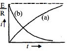
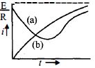
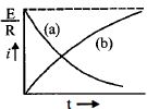
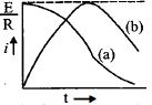
In the circuits $(a)$ and $(b)$,switches $S_1$ and $S_2$ are closed at $t = 0$ and are kept closed for a long time. The variations of current in the two circuits for $t \ge 0$ are roughly shown by which figure? (Figures are schematic and not drawn to scale.)
- A
- B
- C
- D
Explore More
Similar Questions
An inductance coil has a time constant of $4 \, sec$. If it is cut into two equal parts and connected in parallel,then the new time constant of the circuit is.....$sec$.
Medium
View SolutionIn an $LR$ circuit,the current increases to one-fourth of its maximum value in $4 \, sec$. What is the time constant of the circuit?
Medium
View SolutionIn the circuit shown here, the point '$C$' is kept connected to point '$A$' till the current flowing through the circuit becomes constant. Afterward, suddenly, point '$C$' is disconnected from point '$A$' and connected to point '$B$' at time $t = 0$. The ratio of the voltage across the resistance $(V_R)$ and the inductor $(V_L)$ at $t = L/R$ will be equal to:
For the given circuit,the current $i$ through the battery when the key is closed and the steady state has been reached is .....$A$.
DifficultJEE MAIN 2021
View SolutionThe resistance in the following circuit is increased at a particular instant. At this instant,the value of resistance is $10\,\Omega$. The current in the circuit will be
Difficult
View SolutionVedclass Products
For Students
Vedclass Test Series
Mock tests in real JEE/NEET style with performance analysis. 5-day free trial.
Start Free TrialFor Teachers
Exam Paper Generator
Generate Set A/B/C/D exam papers from 7.5L+ questions in 2 minutes. 3 chapters free.
Try FreeFor Institutes
Online Exam Module
Live online exams with unlimited students, 360° analytics & white-label branding.
See Demo