
A English
Circuit Solving for current and Voltage Questions in English
Class 12 Physics · Current Electricity · Circuit Solving for current and Voltage
684+
Questions
English
Language
100%
With Solutions
Showing 50 of 684 questions in English
451
MediumMCQ
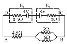
In the given circuit,calculate the value of current in the $4.5\,\Omega$ resistor in $A$.
A
$1$
B
$1.5$
C
$0.25$
D
$0.5$
Solution
(D) First,calculate the net electromotive force $(E_{net})$ and net internal resistance $(r_{net})$ of the battery combination. The batteries are connected in series with opposing polarities. Thus,$E_{net} = 8\,V - 4\,V = 4\,V$. The internal resistances are in series,so $r_{net} = 0.5\,\Omega + 1.0\,\Omega = 1.5\,\Omega$.
Next,calculate the equivalent resistance of the external circuit. The $3\,\Omega$ and $6\,\Omega$ resistors are in parallel,so their equivalent resistance $R_p = \frac{3 \times 6}{3 + 6} = \frac{18}{9} = 2\,\Omega$. This is in series with the $4.5\,\Omega$ resistor,so the total external resistance $R_{ext} = 4.5\,\Omega + 2\,\Omega = 6.5\,\Omega$.
The total resistance of the circuit is $R_{total} = R_{ext} + r_{net} = 6.5\,\Omega + 1.5\,\Omega = 8.0\,\Omega$.
Finally,the total current in the circuit is $I = \frac{E_{net}}{R_{total}} = \frac{4\,V}{8.0\,\Omega} = 0.5\,A$. Since the $4.5\,\Omega$ resistor is in the main branch,the current flowing through it is $0.5\,A$.
0 likes
View Solution452
MediumMCQ
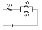
If the power dissipated in the $3\,\Omega$ resistor is $27\,W$,then what is the power dissipated in the $2\,\Omega$ resistor (in $,W$)?
A
$8$
B
$16$
C
$12$
D
$15$
Solution
(A) First,calculate the equivalent resistance of the parallel combination of $2\,\Omega$ and $4\,\Omega$ resistors:
$R_p = \frac{2 \times 4}{2 + 4} = \frac{8}{6} = \frac{4}{3}\,\Omega$.
In the circuit,the $3\,\Omega$ resistor is in series with the parallel combination $(4/3\,\Omega)$.
Since the current $I$ is the same for components in series,the power $P = I^2 R$ is proportional to resistance $(P \propto R)$.
Given power in $3\,\Omega$ resistor is $P_3 = 27\,W$,let $P_p$ be the power in the parallel combination:
$\frac{P_3}{P_p} = \frac{R_3}{R_p} \Rightarrow \frac{27}{P_p} = \frac{3}{4/3} = \frac{9}{4}$.
$P_p = 27 \times \frac{4}{9} = 12\,W$.
Now,for the parallel combination,the voltage $V_p$ across both resistors is the same. Power $P = V^2/R$,so $P \propto 1/R$.
$\frac{P_2}{P_4} = \frac{R_4}{R_2} = \frac{4}{2} = 2 \Rightarrow P_2 = 2 P_4$.
Since $P_2 + P_4 = P_p = 12\,W$,we have $2 P_4 + P_4 = 12\,W \Rightarrow 3 P_4 = 12\,W \Rightarrow P_4 = 4\,W$.
Therefore,$P_2 = 2 \times 4 = 8\,W$.
0 likes
View Solution453
MediumMCQ
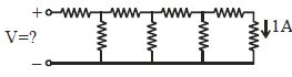
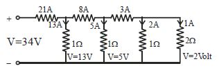
Each element in the finite chain of resistors shown in the figure is $1\,\Omega $. $A$ current of $1\, A$ flows through the final element. Then what is the potential difference $V$ across input terminals of the chain (in $,V$)?
A
$12$
B
$34$
C
$1$
D
$16$
Solution
(B) Let the potential across the last resistor be $V_4 = 2\,V$ (since $I = 1\,A$ and $R = 2\,\Omega$ is not correct,the diagram shows the last vertical resistor is $1\,\Omega$ and the last horizontal is $1\,\Omega$).
Working backwards from the end:
$1$. The last vertical resistor has $1\,A$ current flowing through it,so its potential is $V_4 = 1\,A \times 1\,\Omega = 1\,V$.
$2$. The current through the last horizontal resistor is $1\,A$. The potential drop across it is $1\,A \times 1\,\Omega = 1\,V$. So,the potential before this resistor is $1\,V + 1\,V = 2\,V$.
$3$. The current through the next vertical resistor is $V/R = 2\,V / 1\,\Omega = 2\,A$. Total current entering this node is $1\,A + 2\,A = 3\,A$.
$4$. Potential drop across the next horizontal resistor is $3\,A \times 1\,\Omega = 3\,V$. Potential before this is $2\,V + 3\,V = 5\,V$.
$5$. Current through the next vertical resistor is $5\,V / 1\,\Omega = 5\,A$. Total current is $3\,A + 5\,A = 8\,A$.
$6$. Potential drop across the next horizontal resistor is $8\,A \times 1\,\Omega = 8\,V$. Potential before this is $5\,V + 8\,V = 13\,V$.
$7$. Current through the next vertical resistor is $13\,V / 1\,\Omega = 13\,A$. Total current is $8\,A + 13\,A = 21\,A$.
$8$. Potential drop across the first horizontal resistor is $21\,A \times 1\,\Omega = 21\,V$. Total input potential is $13\,V + 21\,V = 34\,V$.
0 likes
View Solution454
DifficultMCQ
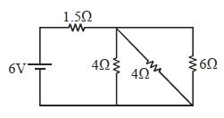
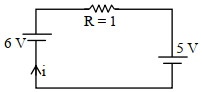
For the circuit shown in the figure,the power delivered by the battery is ................ $W$.
A
$9$
B
$12$
C
$24$
D
$18$
Solution
(B) The circuit consists of a $6 \, V$ battery in series with a $1.5 \, \Omega$ resistor and a parallel combination of three resistors ($4 \, \Omega$,$4 \, \Omega$,and $6 \, \Omega$).
First,calculate the equivalent resistance $(R_p)$ of the three parallel resistors:
$\frac{1}{R_p} = \frac{1}{4} + \frac{1}{4} + \frac{1}{6} = \frac{3+3+2}{12} = \frac{8}{12} = \frac{2}{3} \, \Omega^{-1}$
So,$R_p = 1.5 \, \Omega$.
The total effective resistance of the circuit is $R_{eff} = 1.5 \, \Omega + R_p = 1.5 \, \Omega + 1.5 \, \Omega = 3 \, \Omega$.
The power delivered by the battery is given by $P = \frac{V^2}{R_{eff}}$.
Substituting the values,$P = \frac{(6)^2}{3} = \frac{36}{3} = 12 \, W$.
0 likes
View Solution455
MediumMCQ
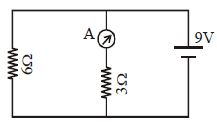
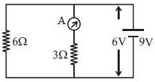
In the figure shown, if the internal resistance of the battery is $1\, \Omega$, the reading of the ammeter will be ................. $A$.
A
$2$
B
$1$
C
$4$
D
$3$
Solution
(A) The circuit consists of a $9\, V$ battery with an internal resistance $r = 1\, \Omega$ connected in series to a parallel combination of two resistors ($6\, \Omega$ and $3\, \Omega$).
First, calculate the equivalent resistance of the parallel part:
$R_p = \frac{6 \times 3}{6 + 3} = \frac{18}{9} = 2\, \Omega$.
The total resistance of the circuit is $R_{\text{total}} = R_p + r = 2\, \Omega + 1\, \Omega = 3\, \Omega$.
The total current flowing from the battery is $I = \frac{E}{R_{\text{total}}} = \frac{9\, V}{3\, \Omega} = 3\, A$.
The terminal potential difference $(V)$ across the parallel combination is $V = E - Ir = 9\, V - (3\, A \times 1\, \Omega) = 6\, V$.
The ammeter is in series with the $3\, \Omega$ resistor. The current through the ammeter is $I_A = \frac{V}{R} = \frac{6\, V}{3\, \Omega} = 2\, A$.
0 likes
View Solution456
MediumMCQ
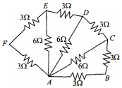
Six resistors of $3 \; \Omega$ each are connected along the sides of a hexagon and three resistors of $6 \; \Omega$ each are connected along $AC$, $AD$, and $AE$ as shown in the figure. The equivalent resistance between $A$ and $B$ is equal to
A
$3 \; \Omega$
B
$2 \; \Omega$
C
$6 \; \Omega$
D
$9 \; \Omega$
Solution
(B) The circuit can be simplified by observing the symmetry and series-parallel combinations.
$1$. The resistors along $AF$ and $FE$ are in series. Their equivalent resistance is $R_1 = 3 \; \Omega + 3 \; \Omega = 6 \; \Omega$.
$2$. This $R_1$ is in parallel with the $6 \; \Omega$ resistor connected along $AE$. The equivalent resistance $R_{AE}'$ is given by $\frac{1}{R_{AE}'} = \frac{1}{6} + \frac{1}{6} = \frac{2}{6} = \frac{1}{3} \Rightarrow R_{AE}' = 3 \; \Omega$.
$3$. Similarly, the resistors along $ED$ and $DC$ are in series with the $6 \; \Omega$ resistor along $AD$ in parallel, leading to an equivalent resistance of $3 \; \Omega$ between $A$ and $C$.
$4$. Finally, the circuit reduces to three resistors of $3 \; \Omega$ each connected between $A$ and $B$ (one directly, and two through path $C$).
$5$. The equivalent resistance $R_{eq}$ is the parallel combination of the direct $3 \; \Omega$ resistor and the series combination of the other two $3 \; \Omega$ resistors $(3+3=6 \; \Omega)$.
$6$. $R_{eq} = \frac{3 \times 6}{3 + 6} = \frac{18}{9} = 2 \; \Omega$.
0 likes
View Solution457
DifficultMCQ
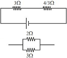
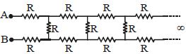
The resistance between points $A$ and $B$ is
A
$(\sqrt{3} + 1)R$
B
$(\sqrt{3} - 1)R$
C
$4R$
D
$(\sqrt{3} + 2)R$
Solution
(A) Let the equivalent resistance between points $A$ and $B$ be $r$. Since the circuit is an infinite ladder,adding one more section to the input does not change the total resistance. Thus,the circuit can be represented as two resistors of resistance $R$ in series with the parallel combination of a resistor $R$ and the equivalent resistance $r$.
The equivalent resistance $r$ is given by:
$r = R + R + \frac{R \cdot r}{R + r}$
$r = 2R + \frac{Rr}{R + r}$
Multiplying by $(R + r)$:
$r(R + r) = 2R(R + r) + Rr$
$Rr + r^2 = 2R^2 + 2Rr + Rr$
$r^2 - 2Rr - 2R^2 = 0$
Using the quadratic formula $r = \frac{-b \pm \sqrt{b^2 - 4ac}}{2a}$:
$r = \frac{2R \pm \sqrt{(-2R)^2 - 4(1)(-2R^2)}}{2(1)}$
$r = \frac{2R \pm \sqrt{4R^2 + 8R^2}}{2}$
$r = \frac{2R \pm \sqrt{12R^2}}{2}$
$r = \frac{2R \pm 2R\sqrt{3}}{2}$
$r = R \pm R\sqrt{3}$
Since resistance must be positive,we take the positive root:
$r = (1 + \sqrt{3})R$
0 likes
View Solution458
MediumMCQ
Two resistances,each equal to $R_0$ at $0\,^oC$,have temperature coefficients of resistance $\alpha_1$ and $\alpha_2$. When they are joined in series,the temperature coefficient of the equivalent resistance is:
A
$\alpha_1 + \alpha_2$
B
$\frac{\alpha_1 \alpha_2}{\alpha_1 + \alpha_2}$
C
$\frac{\alpha_1 - \alpha_2}{2}$
D
$\frac{\alpha_1 + \alpha_2}{2}$
Solution
(D) Let the resistances at $0\,^oC$ be $R_0$ for both resistors.
At temperature $t$,the resistances are $R_1 = R_0(1 + \alpha_1 t)$ and $R_2 = R_0(1 + \alpha_2 t)$.
When connected in series,the equivalent resistance $R_{eq}$ is $R_1 + R_2$.
$R_{eq} = R_0(1 + \alpha_1 t) + R_0(1 + \alpha_2 t) = 2R_0 + R_0(\alpha_1 + \alpha_2)t$.
$R_{eq} = 2R_0 \left( 1 + \frac{\alpha_1 + \alpha_2}{2} t \right)$.
Since the equivalent resistance at $0\,^oC$ is $R'_{0} = 2R_0$,we have $R_{eq} = R'_{0}(1 + \alpha_{eq} t)$.
Comparing the two expressions,the equivalent temperature coefficient is $\alpha_{eq} = \frac{\alpha_1 + \alpha_2}{2}$.
0 likes
View Solution459
MediumMCQ
$A$ constant voltage is applied between the two ends of a uniform metallic wire. Some heat is developed in it. The heat developed is doubled if
A
both the length and radius of the wire are halved
B
both the length and radius of the wire are doubled
C
the radius of the wire is doubled
D
the length of the wire is doubled
Solution
(B) The heat developed in a wire with constant voltage $V$ is given by $H = \frac{V^2}{R} t$. For the heat to be doubled,the resistance $R$ must be halved $(R' = R/2)$.
Resistance is given by $R = \frac{\rho \ell}{A} = \frac{\rho \ell}{\pi r^2}$.
If both length $\ell$ and radius $r$ are halved,$\ell' = \ell/2$ and $r' = r/2$.
Then $R' = \frac{\rho (\ell/2)}{\pi (r/2)^2} = \frac{\rho \ell / 2}{\pi r^2 / 4} = 2 \left( \frac{\rho \ell}{\pi r^2} \right) = 2R$.
If both length $\ell$ and radius $r$ are doubled,$\ell' = 2\ell$ and $r' = 2r$.
Then $R' = \frac{\rho (2\ell)}{\pi (2r)^2} = \frac{2\rho \ell}{4\pi r^2} = \frac{1}{2} \left( \frac{\rho \ell}{\pi r^2} \right) = \frac{R}{2}$.
Since $R' = R/2$,the heat $H' = \frac{V^2}{R'} t = \frac{V^2}{R/2} t = 2 \left( \frac{V^2}{R} t \right) = 2H$. Thus,the heat is doubled.
0 likes
View Solution460
MediumMCQ
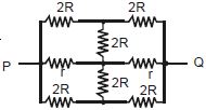
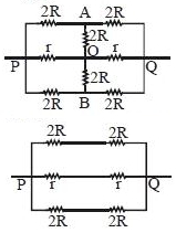
The effective resistance between points $P$ and $Q$ of the electrical circuit shown in the figure is
A
$\frac{2Rr}{R + r}$
B
$\frac{8R(R + r)}{3R + r}$
C
$2r + 4R$
D
$\frac{5R}{2} + 2r$
Solution
(A) The circuit is symmetrical about the axis $POQ$. Due to symmetry,the potential at nodes $A$ and $B$ is the same as the potential at node $O$. Thus,no current flows through the vertical resistors of resistance $2R$ connected to $O$.
The circuit simplifies to three parallel branches between $P$ and $Q$:
$1$. Top branch: Two $2R$ resistors in series,total $= 4R$.
$2$. Middle branch: Two $r$ resistors in series,total $= 2r$.
$3$. Bottom branch: Two $2R$ resistors in series,total $= 4R$.
The equivalent resistance $R_{PQ}$ is given by:
$\frac{1}{R_{PQ}} = \frac{1}{4R} + \frac{1}{2r} + \frac{1}{4R} = \frac{2}{4R} + \frac{1}{2r} = \frac{1}{2R} + \frac{1}{2r} = \frac{r + R}{2Rr}$.
Therefore,$R_{PQ} = \frac{2Rr}{R + r}$.
0 likes
View Solution461
DifficultMCQ
$A$ current source drives a current in a coil of resistance $R_1$ for a time $t$. The same source drives current in another coil of resistance $R_2$ for the same time. If the heat generated is the same,find the internal resistance of the source.
A
$\frac{R_1 R_2}{R_1 + R_2}$
B
$R_1 + R_2$
C
$0$
D
$\sqrt{R_1 R_2}$
Solution
(D) Let the internal resistance of the source be $r$ and its electromotive force be $E$.
The current in the coil of resistance $R_1$ is $I_1 = \frac{E}{r + R_1}$.
The current in the coil of resistance $R_2$ is $I_2 = \frac{E}{r + R_2}$.
Since the heat generated $H = I^2 R t$ is the same for both coils in the same time $t$,we have:
$I_1^2 R_1 t = I_2^2 R_2 t$
Substituting the expressions for $I_1$ and $I_2$:
$\left(\frac{E}{r + R_1}\right)^2 R_1 = \left(\frac{E}{r + R_2}\right)^2 R_2$
$\frac{R_1}{(r + R_1)^2} = \frac{R_2}{(r + R_2)^2}$
Taking the square root on both sides:
$\frac{\sqrt{R_1}}{r + R_1} = \frac{\sqrt{R_2}}{r + R_2}$
$\sqrt{R_1}(r + R_2) = \sqrt{R_2}(r + R_1)$
$r\sqrt{R_1} + \sqrt{R_1}R_2 = r\sqrt{R_2} + R_1\sqrt{R_2}$
$r(\sqrt{R_1} - \sqrt{R_2}) = R_1\sqrt{R_2} - \sqrt{R_1}R_2$
$r(\sqrt{R_1} - \sqrt{R_2}) = \sqrt{R_1 R_2}(\sqrt{R_1} - \sqrt{R_2})$
$r = \sqrt{R_1 R_2}$
0 likes
View Solution462
MediumMCQ
Assertion : In a simple battery circuit,the point of the lowest potential is the negative terminal of the battery.
Reason : The current flows towards the point of the higher potential,as it does in such a circuit from the negative to the positive terminal.
Reason : The current flows towards the point of the higher potential,as it does in such a circuit from the negative to the positive terminal.
A
If both Assertion and Reason are correct and Reason is the correct explanation of Assertion.
B
If both Assertion and Reason are correct,but Reason is not the correct explanation of Assertion.
C
If Assertion is correct but Reason is incorrect.
D
If both the Assertion and Reason are incorrect.
Solution
(C) The positive terminal of a battery is at the highest potential,and the negative terminal is at the lowest potential.
By convention,the electric current flows from the point of higher potential to the point of lower potential,which is from the positive terminal to the negative terminal in an external circuit.
The Assertion is correct because the negative terminal is indeed the point of lowest potential.
The Reason is incorrect because current flows from higher potential to lower potential,not the other way around.
0 likes
View Solution463
EasyMCQ
Which of the following acts as a circuit protection device?
A
conductor
B
inductor
C
switch
D
fuse
Solution
(D) fuse is a safety device used in electrical circuits to protect against overcurrent or short-circuit conditions. When the current exceeds a safe limit,the fuse wire melts due to the heating effect of the electric current,thereby breaking the circuit and preventing damage to appliances.
0 likes
View Solution464
MediumMCQ
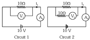
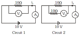
In the circuits shown below, the readings of the voltmeters and the ammeters will be:
A
$V_{2} > V_{1}$ and $I_{1} = I_{2}$
B
$V_{1} = V_{2}$ and $I_{1} > I_{2}$
C
$V_{1} = V_{2}$ and $I_{1} = I_{2}$
D
$V_{2} > V_{1}$ and $I_{1} > I_{2}$
Solution
(C) In Circuit $1$, the voltmeter $V_{1}$ is connected in parallel with the $10 \; \Omega$ resistor. Since an ideal voltmeter has infinite resistance, it draws no current. Thus, the voltage across the $10 \; \Omega$ resistor is $10 \; V$, so $V_{1} = 10 \; V$. The current $I_{1}$ is given by $I_{1} = \frac{10 \; V}{10 \; \Omega} = 1 \; A$.
In Circuit $2$, the voltmeter $V_{2}$ is connected in series with a $10 \; \Omega$ resistor, and this combination is in parallel with the main $10 \; \Omega$ resistor. An ideal voltmeter has infinite resistance, so the branch containing the voltmeter and the $10 \; \Omega$ resistor draws no current. The voltage across this branch is still $10 \; V$. Since the voltmeter is ideal, the entire potential drop of $10 \; V$ appears across the voltmeter itself, so $V_{2} = 10 \; V$. The current $I_{2}$ flows only through the main $10 \; \Omega$ resistor, so $I_{2} = \frac{10 \; V}{10 \; \Omega} = 1 \; A$.
Therefore, $V_{1} = V_{2} = 10 \; V$ and $I_{1} = I_{2} = 1 \; A$.
0 likes
View Solution465
MediumMCQ
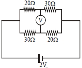
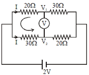
The reading of an ideal voltmeter in the circuit shown is.....$V$.
A
$0.6$
B
$0$
C
$0.5$
D
$0.4$
Solution
(D) The circuit consists of two parallel branches connected to a $2 \text{ V}$ battery.
In the upper branch,the resistors $20 \ \Omega$ and $30 \ \Omega$ are in series. The potential at the junction $V_1$ is given by the voltage divider rule: $V_1 = 2 \text{ V} \times \frac{30 \ \Omega}{20 \ \Omega + 30 \ \Omega} = 2 \times \frac{30}{50} = 1.2 \text{ V}$.
In the lower branch,the resistors $30 \ \Omega$ and $20 \ \Omega$ are in series. The potential at the junction $V_2$ is given by: $V_2 = 2 \text{ V} \times \frac{20 \ \Omega}{30 \ \Omega + 20 \ \Omega} = 2 \times \frac{20}{50} = 0.8 \text{ V}$.
The reading of the ideal voltmeter is the potential difference between the two junctions: $V = |V_1 - V_2| = |1.2 \text{ V} - 0.8 \text{ V}| = 0.4 \text{ V}$.
0 likes
View Solution466
DifficultMCQ
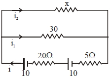
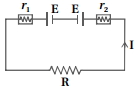
The series combination of two batteries,both of the same emf $10 \; V,$ but different internal resistances of $20 \; \Omega$ and $5 \; \Omega,$ is connected to the parallel combination of two resistors $30 \; \Omega$ and $R \; \Omega.$ If the voltage difference across the battery of internal resistance $20 \; \Omega$ is zero,the value of $R$ (in $\Omega$) is:
A
$30$
B
$26$
C
$36$
D
$15$
Solution
(A) Let the current in the circuit be $i.$ The batteries are in series,so the total emf is $E_{eq} = 10 + 10 = 20 \; V$ and the total internal resistance is $r_{eq} = 20 + 5 = 25 \; \Omega.$
The voltage across the battery with internal resistance $20 \; \Omega$ is given by $V_1 = E - i r_1 = 10 - i(20).$
Given $V_1 = 0,$ we have $10 - 20i = 0,$ which gives $i = 0.5 \; A.$
The total external resistance $R_{ext}$ is the parallel combination of $30 \; \Omega$ and $R \; \Omega,$ so $R_{ext} = \frac{30R}{30+R}.$
Using Ohm's law for the whole circuit,$E_{eq} = i(R_{ext} + r_{eq}).$
$20 = 0.5 \left( \frac{30R}{30+R} + 25 \right).$
$40 = \frac{30R}{30+R} + 25.$
$15 = \frac{30R}{30+R}.$
$15(30+R) = 30R.$
$450 + 15R = 30R.$
$15R = 450 \implies R = 30 \; \Omega.$
1 likes
View Solution467
MediumMCQ
An electric toaster uses nichrome for its heating element. When a negligibly small current passes through it,its resistance at room temperature $(27.0^{\circ} C)$ is found to be $75.3\; \Omega$. When the toaster is connected to a $230\; V$ supply,the current settles,after a few seconds,to a steady value of $2.68\; A$. What is the steady temperature (in $^{\circ} C$) of the nichrome element? The temperature coefficient of resistance of nichrome averaged over the temperature range involved is $1.70 \times 10^{-4}\; ^{\circ} C^{-1}$.
A
$820$
B
$1093$
C
$847$
D
$1120$
Solution
(C) When the current through the element is very small,heating effects can be ignored and the temperature $T_{1}$ of the element is the same as room temperature.
When the toaster is connected to the supply,its initial current will be slightly higher than its steady value of $2.68\; A$. But due to the heating effect of the current,the temperature will rise. This will cause an increase in resistance and a slight decrease in current.
In a few seconds,a steady state will be reached when the temperature will rise no further,and both the resistance of the element and the current drawn will achieve steady values.
The resistance $R_{2}$ at the steady temperature $T_{2}$ is:
$R_{2} = \frac{230\; V}{2.68\; A} = 85.8\; \Omega$
Using the relation:
$R_{2} = R_{1}[1 + \alpha(T_{2} - T_{1})]$
With $\alpha = 1.70 \times 10^{-4}\; ^{\circ} C^{-1}$,we get:
$T_{2} - T_{1} = \frac{(85.8 - 75.3)}{(75.3) \times 1.70 \times 10^{-4}} = 820^{\circ} C$
That is,$T_{2} = (820 + 27.0)^{\circ} C = 847^{\circ} C$.
Thus,the steady temperature of the heating element is $847^{\circ} C$.
0 likes
View Solution468
EasyMCQ
The storage battery of a car has an $emf$ of $12\; V$. If the internal resistance of the battery is $0.4\; \Omega,$ what is the maximum current (in $A$) that can be drawn from the battery?
A
$18$
B
$25$
C
$30$
D
$36$
Solution
(C) The $emf$ of the battery is given as $E = 12\; V$.
The internal resistance of the battery is $r = 0.4\; \Omega$.
To draw the maximum current $(I_{max})$ from a battery,the external resistance connected to the circuit must be zero (short circuit condition).
According to Ohm's law for a circuit,the current is given by $I = \frac{E}{R + r}$.
For maximum current,we set the external resistance $R = 0$.
Therefore,$I_{max} = \frac{E}{r} = \frac{12}{0.4}$.
$I_{max} = \frac{120}{4} = 30\; A$.
Thus,the maximum current that can be drawn from the battery is $30\; A$.
0 likes
View Solution469
Medium
$A$ battery of $emf$ $10 \;V$ and internal resistance $3\; \Omega$ is connected to a resistor. If the current in the circuit is $0.5 \;A$,what is the resistance of the resistor? What is the terminal voltage of the battery when the circuit is closed?
Solution
(N/A) $Emf$ of the battery,$E = 10 \;V$
Internal resistance of the battery,$r = 3 \;\Omega$
Current in the circuit,$I = 0.5 \;A$
Let the resistance of the resistor be $R$.
Using Ohm's law for the entire circuit,$I = \frac{E}{R + r}$.
Rearranging for $R + r$,we get $R + r = \frac{E}{I} = \frac{10}{0.5} = 20 \;\Omega$.
Thus,$R = 20 - 3 = 17 \;\Omega$.
The terminal voltage $V$ of the battery is given by $V = E - Ir$ or $V = IR$.
Using $V = IR$,we get $V = 0.5 \;A \times 17 \;\Omega = 8.5 \;V$.
Therefore,the resistance of the resistor is $17 \;\Omega$ and the terminal voltage of the battery is $8.5 \;V$.
0 likes
View Solution470
Medium
$A$ storage battery of $emf$ $8.0\; V$ and internal resistance $0.5\; \Omega$ is being charged by a $120\; V$ $DC$ supply using a series resistor of $15.5\; \Omega$. What is the terminal voltage of the battery during charging? What is the purpose of having a series resistor in the charging circuit?
Solution
(C) Given: $Emf$ of the storage battery,$E = 8.0\; V$. Internal resistance of the battery,$r = 0.5\; \Omega$. $DC$ supply voltage,$V = 120\; V$. Resistance of the series resistor,$R = 15.5\; \Omega$.
The effective voltage in the circuit is $V' = V - E = 120 - 8.0 = 112\; V$.
The total resistance in the circuit is $R_{total} = R + r = 15.5 + 0.5 = 16.0\; \Omega$.
The charging current $I$ is given by $I = \frac{V'}{R_{total}} = \frac{112}{16.0} = 7.0\; A$.
The terminal voltage of the battery during charging is given by $V_{terminal} = E + Ir = 8.0 + (7.0 \times 0.5) = 8.0 + 3.5 = 11.5\; V$.
The purpose of the series resistor is to limit the charging current to a safe value,preventing damage to the battery and the power supply due to excessive current flow.
0 likes
View Solution471
MediumMCQ
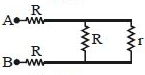
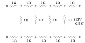
Determine the current (in $A$) drawn from a $12\; V$ supply with internal resistance $0.5\; \Omega$ by the infinite network shown in the figure. Each resistor has $1\; \Omega$ resistance.
A
$1.16$
B
$8.34$
C
$3.72$
D
$5.61$
Solution
(C) Let the equivalent resistance of the infinite network be $R^{\prime}$.
Since the network is infinite,adding one more section of the same structure will not change the equivalent resistance.
The network consists of two $1\; \Omega$ resistors in series with the rest of the infinite network,which is in parallel with a $1\; \Omega$ shunt resistor.
Thus,$R^{\prime} = 1 + 1 + \frac{R^{\prime} \times 1}{R^{\prime} + 1} = 2 + \frac{R^{\prime}}{R^{\prime} + 1}$.
Multiplying by $(R^{\prime} + 1)$,we get $R^{\prime}(R^{\prime} + 1) = 2(R^{\prime} + 1) + R^{\prime}$.
$(R^{\prime})^2 + R^{\prime} = 2R^{\prime} + 2 + R^{\prime}$.
$(R^{\prime})^2 - 2R^{\prime} - 2 = 0$.
Using the quadratic formula $R^{\prime} = \frac{-b \pm \sqrt{b^2 - 4ac}}{2a}$,we get $R^{\prime} = \frac{2 \pm \sqrt{4 - 4(1)(-2)}}{2} = \frac{2 \pm \sqrt{12}}{2} = 1 \pm \sqrt{3}$.
Since resistance cannot be negative,$R^{\prime} = 1 + \sqrt{3} \approx 1 + 1.732 = 2.732\; \Omega$.
The total resistance of the circuit including the internal resistance $r = 0.5\; \Omega$ is $R_{total} = R^{\prime} + r = 2.732 + 0.5 = 3.232\; \Omega$.
The current drawn from the $12\; V$ supply is $I = \frac{V}{R_{total}} = \frac{12}{3.232} \approx 3.713\; A$.
Rounding to two decimal places,the current is $3.72\; A$.
0 likes
View Solution472
Medium
What is called earthing? Give the importance of earthing in electrical wiring.
Solution
(N/A) Earthing is the process of connecting the metallic body of an electrical appliance or a circuit to the Earth (ground) using a low-resistance conductor.
Importance of earthing:
$1$. Safety: It provides a low-resistance path for leakage current to flow into the ground,preventing electric shocks to users if the appliance's body becomes live due to insulation failure.
$2$. Protection: It protects electrical equipment from damage caused by voltage surges or lightning strikes by providing a safe path for excess charge to dissipate into the Earth.
$3$. Stability: It helps maintain a stable reference potential (zero potential) for the electrical system.
0 likes
View Solution473
Difficult
Two cells of same $emf$ $E$ but internal resistances $r_1$ and $r_2$ are connected in series to an external resistor $R$ (as shown in the figure). What should be the value of $R$ so that the potential difference across the terminals of the first cell becomes zero?
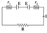
Solution
(R = R_1 - R_2) The equivalent internal resistance of the series combination is $r = r_1 + r_2$.
The equivalent $emf$ of the series combination is $E' = E + E = 2E$.
Therefore,the current $I$ flowing in the circuit is given by:
$I = \frac{E'}{R + r} = \frac{2E}{R + r_1 + r_2}$
The potential difference $V_1$ across the terminals of the first cell is given by:
$V_1 = E - I r_1$
Given that the potential difference across the first cell is zero,we set $V_1 = 0$:
$0 = E - I r_1$
$E = I r_1$
Substituting the expression for $I$:
$E = \left( \frac{2E}{R + r_1 + r_2} \right) r_1$
$1 = \frac{2 r_1}{R + r_1 + r_2}$
$R + r_1 + r_2 = 2 r_1$
$R = r_1 - r_2$
Thus,the required value of the external resistance is $R = r_1 - r_2$.
0 likes
View Solution474
Medium
Suppose there is a circuit consisting of only resistances and batteries. Suppose one is to double (or increase it to $n$-times) all voltages and all resistances. Show that currents are unaltered.
Solution
(N/A) Let the equivalent internal resistance of the given cells be $R_{eq}$,the equivalent voltage be $V_{eq}$,and the external resistance be $R$.
From Ohm's law,the initial current $I_{1}$ is given by:
$I_{1} = \frac{V_{eq}}{R_{eq} + R}$ $(1)$
When the values of all resistors and all batteries are made $n$ times their initial values,the new parameters become:
$V'_{eq} = n V_{eq}$,$R'_{eq} = n R_{eq}$,and $R' = n R$.
The current in the new (modified) circuit,$I_{2}$,is:
$I_{2} = \frac{V'_{eq}}{R'_{eq} + R'} = \frac{n V_{eq}}{n R_{eq} + n R} = \frac{n V_{eq}}{n(R_{eq} + R)} = \frac{V_{eq}}{R_{eq} + R}$ $(2)$
Comparing $(1)$ and $(2)$,
$I_{2} = I_{1}$
Thus,the currents remain unaltered.
0 likes
View Solution475
DifficultMCQ
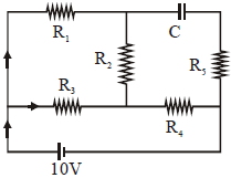
An ideal cell of emf $10\, V$ is connected in the circuit shown in the figure. Each resistance is $2\, \Omega$. The potential difference (in $V$) across the capacitor when it is fully charged is
A
$8$
B
$10$
C
$15$
D
$25$
Solution
(A) Given that all resistances $R_1$ to $R_5$ are $2\, \Omega$. When the capacitor is fully charged,no current flows through the branch containing the capacitor.
Let the nodes be marked as shown in the solution figure. The branch $ADB$ contains the capacitor,so no current flows through it.
The circuit simplifies to a combination of resistors where $R_1$ and $R_2$ are in series,and this combination is in parallel with $R_3$. This whole block is in series with $R_4$.
However,looking at the circuit,the current $i$ from the $10\, V$ source splits. The effective resistance $R_{eq}$ is calculated as follows:
The branch $AEB$ is not carrying current through the capacitor. The current flows through $R_1$ and $R_2$ in series $(2+2=4\, \Omega)$,which is in parallel with $R_3$ $(2\, \Omega)$.
Equivalent resistance of this part $= (4 \times 2) / (4 + 2) = 8 / 6 = 4/3\, \Omega$.
Adding $R_4$ in series,$R_{eq} = 4/3 + 2 = 10/3\, \Omega$.
Total current $i = V / R_{eq} = 10 / (10/3) = 3\, A$.
The potential difference across the capacitor is the potential difference between points $A$ and $B$,which is $V_{AB} = V_{AE} + V_{EB}$.
$V_{AE} = I_{R2} \times R_2 = 1\, A \times 2\, \Omega = 2\, V$.
$V_{EB} = I_{R4} \times R_4 = 3\, A \times 2\, \Omega = 6\, V$.
Thus,$V_{AB} = 2\, V + 6\, V = 8\, V$.
0 likes
View Solution476
MediumMCQ
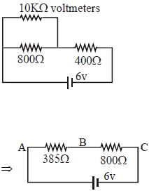
Two resistors $400 \, \Omega$ and $800 \, \Omega$ are connected in series across a $6 \, V$ battery. The potential difference measured by a voltmeter of $10 \, k \Omega$ connected across the $400 \, \Omega$ resistor is close to $.... \, V$.
A
$2$
B
$1.95$
C
$2.05$
D
$1.8$
Solution
(B) The voltmeter of resistance $R_v = 10 \, k \Omega = 10000 \, \Omega$ is connected in parallel with the $400 \, \Omega$ resistor.
First,calculate the equivalent resistance $R_p$ of the parallel combination of the $400 \, \Omega$ resistor and the $10000 \, \Omega$ voltmeter:
$R_p = \frac{400 \times 10000}{400 + 10000} = \frac{4000000}{10400} \approx 384.6 \, \Omega \approx 385 \, \Omega$.
Now,this combination is in series with the $800 \, \Omega$ resistor. The total resistance of the circuit is $R_{eq} = 385 \, \Omega + 800 \, \Omega = 1185 \, \Omega$.
The potential difference across the parallel combination (measured by the voltmeter) is given by the voltage divider rule:
$V = V_{total} \times \frac{R_p}{R_{eq}} = 6 \, V \times \frac{385 \, \Omega}{1185 \, \Omega} \approx 1.949 \, V$.
Rounding this value,we get $1.95 \, V$.
0 likes
View Solution477
DifficultMCQ
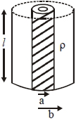
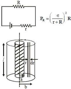
Model a torch battery of length $l$ to be made up of a thin cylindrical bar of radius $a$ and a concentric thin cylindrical shell of radius $b$,filled in between with an electrolyte of resistivity $\rho$ (see figure). If the battery is connected to a resistance of value $R$,the maximum Joule heating in $R$ will take place for:
A
$R = \frac{2 \rho}{\pi l} \ln \left(\frac{b}{a}\right)$
B
$R = \frac{\rho}{\pi l} \ln \left(\frac{b}{a}\right)$
C
$R = \frac{\rho}{2 \pi l} \left(\frac{b}{a}\right)$
D
$R = \frac{\rho}{2 \pi l} \ln \left(\frac{b}{a}\right)$
Solution
(D) According to the maximum power transfer theorem,the power delivered to an external resistance $R$ is maximum when $R$ is equal to the internal resistance $r$ of the battery.
To find the internal resistance $r$,consider a thin cylindrical shell of radius $r$ and thickness $dr$ within the electrolyte.
The resistance $dr$ of this shell is given by $dr = \frac{\rho \cdot dx}{A}$,where $dx = dr$ and $A = 2 \pi r l$.
Thus,$dr = \frac{\rho \cdot dr}{2 \pi r l}$.
Integrating from $r = a$ to $r = b$ to find the total internal resistance $r$:
$r = \int_{a}^{b} \frac{\rho}{2 \pi l} \frac{dr}{r} = \frac{\rho}{2 \pi l} [\ln r]_{a}^{b} = \frac{\rho}{2 \pi l} \ln \left(\frac{b}{a}\right)$.
Therefore,for maximum Joule heating in $R$,we must have $R = r = \frac{\rho}{2 \pi l} \ln \left(\frac{b}{a}\right)$.
0 likes
View Solution478
MediumMCQ
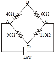
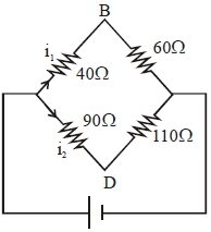
Four resistances $40 \ \Omega, 60 \ \Omega, 90 \ \Omega$,and $110 \ \Omega$ form the arms of a quadrilateral $ABCD$. $A$ battery of emf $40 \ V$ with negligible internal resistance is connected across $AC$. Find the potential difference across $BD$. (in $V$)
A
$4$
B
$1$
C
$2$
D
$5$
Solution
(C) The circuit consists of two parallel branches connected across the $40 \ V$ battery.
Branch $ABC$ has resistances $40 \ \Omega$ and $60 \ \Omega$ in series. Total resistance $R_1 = 40 + 60 = 100 \ \Omega$.
Current $i_1 = \frac{V}{R_1} = \frac{40}{100} = 0.4 \ A$.
Potential at $B$ relative to $A$ is $V_A - V_B = i_1 \times 40 = 0.4 \times 40 = 16 \ V$. Thus,$V_B = V_A - 16$.
Branch $ADC$ has resistances $90 \ \Omega$ and $110 \ \Omega$ in series. Total resistance $R_2 = 90 + 110 = 200 \ \Omega$.
Current $i_2 = \frac{V}{R_2} = \frac{40}{200} = 0.2 \ A$.
Potential at $D$ relative to $A$ is $V_A - V_D = i_2 \times 90 = 0.2 \times 90 = 18 \ V$. Thus,$V_D = V_A - 18$.
The potential difference across $BD$ is $|V_B - V_D| = |(V_A - 16) - (V_A - 18)| = |-16 + 18| = 2 \ V$.
0 likes
View Solution479
DifficultMCQ
$A$ battery of $3.0 \ V$ is connected to a resistor dissipating $0.5 \ W$ of power. If the terminal voltage of the battery is $2.5 \ V$,the power dissipated within the internal resistance is $....... \ W$.
A
$0.50$
B
$0.125$
C
$0.072$
D
$0.10$
Solution
(D) Given:
Electromotive force $E = 3.0 \ V$
Terminal voltage $V = 2.5 \ V$
Power dissipated by external resistor $P_R = 0.5 \ W$
We know that the terminal voltage $V$ is given by $V = E - ir$,where $i$ is the current and $r$ is the internal resistance.
$2.5 = 3.0 - ir$
$ir = 0.5 \ V$
The power dissipated in the internal resistance is $P_r = i^2r = (ir) \cdot i$.
Since $V = iR = 2.5 \ V$,we have $i = \frac{2.5}{R}$.
Also,$P_R = i^2R = 0.5 \ W$.
Substituting $i = \frac{2.5}{R}$ into $P_R = i^2R$:
$0.5 = (\frac{2.5}{R})^2 \cdot R = \frac{6.25}{R}$
$R = \frac{6.25}{0.5} = 12.5 \ \Omega$.
Now,find the current $i$:
$i = \frac{V}{R} = \frac{2.5}{12.5} = 0.2 \ A$.
Finally,calculate the power dissipated in the internal resistance $P_r$:
$P_r = i^2r = i(ir) = 0.2 \ A \times 0.5 \ V = 0.10 \ W$.
0 likes
View Solution480
DifficultMCQ
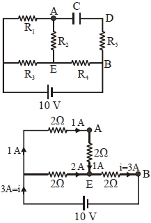
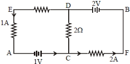
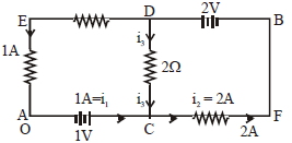
In the circuit shown in the figure,the currents in different branches and the value of one resistor are given. Then,the potential at point $B$ with respect to point $A$ is $.......V$.
A
$+1$
B
$-1$
C
$-2$
D
$+2$
Solution
(A) Let the potential at point $A$ be $V_A = 0 \ V$.
Applying Kirchhoff's Current Law $(KCL)$ at junction $C$:
The current entering from the battery branch is $i_1 = 1 \ A$.
The current flowing through the $2 \ \Omega$ resistor is $i_3$ (downwards from $D$ to $C$).
The current leaving towards $F$ is $i_2 = 2 \ A$.
According to $KCL$ at junction $C$: $i_1 + i_3 = i_2$.
Substituting the values: $1 \ A + i_3 = 2 \ A$,which gives $i_3 = 1 \ A$.
Now,we find the potential at $D$ by traversing from $A$ to $D$ via $C$:
$V_D = V_A + 1 \ V - i_3 \times (2 \ \Omega) = 0 + 1 - (1 \times 2) = -1 \ V$.
Now,we find the potential at $B$ by traversing from $D$ to $B$:
$V_B = V_D + 2 \ V = -1 + 2 = 1 \ V$.
Thus,the potential at point $B$ with respect to point $A$ is $V_B - V_A = 1 - 0 = 1 \ V$.
0 likes
View Solution481
MediumMCQ
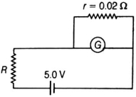
In the circuit shown,the galvanometer $G$ of resistance $60 \, \Omega$ is shunted by a resistance $r = 0.02 \, \Omega$. The current through $R$ is nearly $1 \, A$. The value of resistance $R$ (in $\Omega$) is nearly:
A
$1$
B
$5$
C
$11$
D
$6$
Solution
(B) The galvanometer $G$ has a resistance $R_G = 60 \, \Omega$ and is shunted by a resistance $r = 0.02 \, \Omega$.
The effective resistance $R_P$ of the parallel combination is given by:
$R_P = \frac{R_G \times r}{R_G + r} = \frac{60 \times 0.02}{60 + 0.02} = \frac{1.2}{60.02} \approx 0.02 \, \Omega$.
The total resistance of the circuit is $R_{total} = R + R_P = R + 0.02 \, \Omega$.
Given that the current $I$ through the circuit is $1 \, A$ and the voltage source is $5.0 \, V$,we use Ohm's law:
$I = \frac{V}{R_{total}}$
$1 = \frac{5}{R + 0.02}$
$R + 0.02 = 5$
$R = 5 - 0.02 = 4.98 \, \Omega$.
Thus,the value of $R$ is nearly $5 \, \Omega$.
0 likes
View Solution482
EasyMCQ
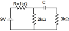
When the capacitor is fully charged,find the current drawn from the $9\, V$ cell (in $mA$).
A
$2$
B
$1$
C
$3$
D
$9$
Solution
(C) When the capacitor is fully charged,it acts as an open circuit,meaning no current flows through the branch containing the capacitor.
The circuit simplifies to a series combination of the $1\, k\Omega$ resistor and the $2\, k\Omega$ resistor connected to the $9\, V$ battery.
The equivalent resistance of the circuit is $R_{eq} = 1\, k\Omega + 2\, k\Omega = 3\, k\Omega$.
Using Ohm's law,the current $I$ drawn from the cell is:
$I = \frac{V}{R_{eq}} = \frac{9\, V}{3\, k\Omega} = 3\, mA$.
0 likes
View Solution483
MediumMCQ
$A$ cell of internal resistance $r$ is connected across an external resistance $n r$. Then the ratio of the terminal voltage to the emf of the cell is
A
$1/n$
B
$1/(n+1)$
C
$n/(n+1)$
D
$(n-1)/n$
Solution
(C) Let the emf of the cell be $E$ and its internal resistance be $r$. The external resistance is $R = n r$.
The total resistance of the circuit is $R_{total} = R + r = n r + r = r(n+1)$.
The current $I$ flowing through the circuit is given by Ohm's law: $I = E / R_{total} = E / [r(n+1)]$.
The terminal voltage $V$ across the external resistance is $V = I R = [E / (r(n+1))] \times (n r)$.
Simplifying the expression,we get $V = E \times [n / (n+1)]$.
Therefore,the ratio of the terminal voltage to the emf is $V/E = n / (n+1)$.
0 likes
View Solution484
DifficultMCQ
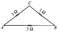
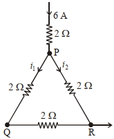
$A$ current of $6\, A$ enters at corner $P$ of an equilateral triangle $PQR$ having $3$ wires of resistance $2 \,\Omega$ each and leaves by the corner $R$. The current $i_{1}$ in ampere is ........ .
A
$2$
B
$1$
C
$3$
D
$4$
Solution
(A) The circuit consists of two parallel branches connected between points $P$ and $R$.
Branch $1$ consists of the wire $PQ$ and $QR$ in series. The resistance of this branch is $R_1 = 2 \,\Omega + 2 \,\Omega = 4 \,\Omega$.
Branch $2$ consists of the wire $PR$ directly,with resistance $R_2 = 2 \,\Omega$.
The total current $I = 6 \, A$ divides into these two parallel branches.
Using the current divider rule,the current $i_1$ flowing through the branch $PQ$ (and then $QR$) is given by:
$i_1 = I \times \frac{R_2}{R_1 + R_2}$
$i_1 = 6 \times \frac{2}{4 + 2} = 6 \times \frac{2}{6} = 2 \, A$.
Thus,the current $i_1$ is $2 \, A$.
0 likes
View Solution485
MediumMCQ
An electric bulb rated $500 \, W$ at $100 \, V$ is used in a circuit having a $200 \, V$ supply. Calculate the resistance $R$ to be connected in series with the bulb so that the power delivered by the bulb is $500 \, W$. (in $\Omega$)
A
$20$
B
$30$
C
$5$
D
$10$
Solution
(A) The rated power of the bulb is $P = 500 \, W$ at a rated voltage $V_{bulb} = 100 \, V$.
The resistance of the bulb is $R_{bulb} = \frac{V_{bulb}^2}{P} = \frac{100^2}{500} = \frac{10000}{500} = 20 \, \Omega$.
Since the bulb is to operate at its rated power of $500 \, W$,it must draw its rated current $I = \frac{P}{V_{bulb}} = \frac{500}{100} = 5 \, A$.
The total supply voltage is $V_{total} = 200 \, V$. The voltage across the bulb is $100 \, V$,so the voltage across the series resistor $R$ must be $V_R = V_{total} - V_{bulb} = 200 - 100 = 100 \, V$.
Using Ohm's law for the series resistor $R$,$V_R = I \times R$.
$100 = 5 \times R$.
$R = \frac{100}{5} = 20 \, \Omega$.
0 likes
View Solution486
EasyMCQ
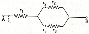
Three resistors having resistances $r_{1}, r_{2}$ and $r_{3}$ are connected as shown in the given circuit. The ratio $\frac{i_{3}}{i_{1}}$ of currents in terms of resistances used in the circuit is :
A
$\frac{r_{1}}{r_{2}+r_{3}}$
B
$\frac{r_{2}}{r_{2}+r_{3}}$
C
$\frac{r_{1}}{r_{1}+r_{2}}$
D
$\frac{r_{2}}{r_{1}+r_{3}}$
Solution
(B) In the given circuit,the current $i_{1}$ splits into two parallel branches containing resistors $r_{2}$ and $r_{3}$.
According to the current divider rule,the current $i_{3}$ flowing through resistor $r_{3}$ is given by:
$i_{3} = i_{1} \left( \frac{r_{2}}{r_{2} + r_{3}} \right)$
Dividing both sides by $i_{1}$,we get the ratio:
$\frac{i_{3}}{i_{1}} = \frac{r_{2}}{r_{2} + r_{3}}$
According to the current divider rule,the current $i_{3}$ flowing through resistor $r_{3}$ is given by:
$i_{3} = i_{1} \left( \frac{r_{2}}{r_{2} + r_{3}} \right)$
Dividing both sides by $i_{1}$,we get the ratio:
$\frac{i_{3}}{i_{1}} = \frac{r_{2}}{r_{2} + r_{3}}$
0 likes
View Solution487
MediumMCQ
An electric bulb rated as $200 \, W$ at $100 \, V$ is used in a circuit having $200 \, V$ supply. The resistance $R$ that must be put in series with the bulb so that the bulb delivers the same power is $..... \, \Omega$.
A
$15$
B
$20$
C
$5$
D
$50$
Solution
(D) The resistance of the bulb $R_B$ is calculated using the formula $P = \frac{V^2}{R_B}$.
Given $P = 200 \, W$ and $V = 100 \, V$, we have $R_B = \frac{100^2}{200} = \frac{10000}{200} = 50 \, \Omega$.
To ensure the bulb delivers the same power, it must operate at its rated voltage of $100 \, V$ even when connected to a $200 \, V$ supply.
Let $R$ be the resistance connected in series. The circuit current $I$ is given by $I = \frac{V_{supply}}{R + R_B} = \frac{200}{R + 50}$.
The voltage across the bulb is $V_B = I \times R_B = 100 \, V$.
Substituting $I$, we get $\frac{200}{R + 50} \times 50 = 100$.
$\frac{10000}{R + 50} = 100 \implies 100 = R + 50 \implies R = 50 \, \Omega$.
0 likes
View Solution488
DifficultMCQ
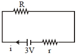
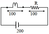
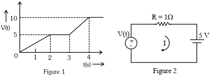
For the circuit shown,the value of current at time $t=3.2 \, s$ will be ...... $A$. (Voltage distribution $V(t)$ is shown by Figure $1$ and the circuit is shown in Figure $2$)
A
$1$
B
$2$
C
$3$
D
$4$
Solution
(A) From the graph in Figure $1$,for the time interval $t=3 \, s$ to $t=4 \, s$,the voltage $V(t)$ increases linearly from $5 \, V$ to $10 \, V$.
The slope of this line is $m = \frac{10-5}{4-3} = 5 \, V/s$.
The equation of the line for $3 \le t \le 4$ is $V(t) - 5 = 5(t - 3)$,which simplifies to $V(t) = 5t - 10$.
At $t = 3.2 \, s$,the voltage is $V(3.2) = 5(3.2) - 10 = 16 - 10 = 6 \, V$.
From the circuit diagram in Figure $2$,applying Kirchhoff's Voltage Law $(KVL)$ in the loop:
$V(t) - iR - 5 = 0$
Given $R = 1 \, \Omega$ and $V(t) = 6 \, V$ at $t = 3.2 \, s$:
$6 - i(1) - 5 = 0$
$i = 1 \, A$.
0 likes
View Solution489
MediumMCQ
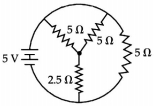
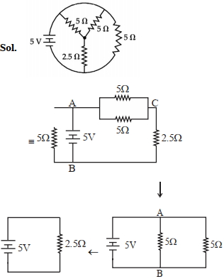
The total current supplied to the circuit as shown in the figure by the $5 \, V$ battery is: (in $, A$)
A
$7$
B
$2$
C
$9$
D
$60$
Solution
(B) $1$. Analyze the circuit: The circuit consists of a $5 \, V$ battery connected to a network of resistors.
$2$. Simplify the circuit: The two $5 \, \Omega$ resistors connected in series to the right are in parallel with the $5 \, \Omega$ resistor connected directly to the battery.
$3$. Let the battery terminals be $A$ and $B$. The resistor of $5 \, \Omega$ is connected directly across $A$ and $B$. The other branch consists of two $5 \, \Omega$ resistors in series,which is $10 \, \Omega$. This $10 \, \Omega$ is in parallel with the $5 \, \Omega$ resistor.
$4$. Equivalent resistance $R_{eq}$ of the parallel combination: $\frac{1}{R_{eq}} = \frac{1}{5} + \frac{1}{10} = \frac{2+1}{10} = \frac{3}{10} \implies R_{eq} = \frac{10}{3} \, \Omega$.
$5$. Total current $I = \frac{V}{R_{eq}} = \frac{5}{10/3} = \frac{15}{10} = 1.5 \, A$.
$6$. Re-evaluating the provided diagram and solution image: The diagram shows a $5 \, V$ battery,a $5 \, \Omega$ resistor,another $5 \, \Omega$ resistor,and a $2.5 \, \Omega$ resistor. Based on the provided solution image,the circuit simplifies to a single $2.5 \, \Omega$ resistor across the $5 \, V$ battery.
$7$. Thus,$I = \frac{V}{R} = \frac{5 \, V}{2.5 \, \Omega} = 2 \, A$.
0 likes
View Solution490
MediumMCQ
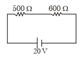
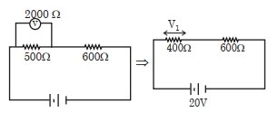
Two resistors are connected in series across a battery as shown in the figure. If a voltmeter of resistance $2000 \,\Omega$ is used to measure the potential difference across the $500 \,\Omega$ resistor,the reading of the voltmeter will be ............... $V$.
A
$8$
B
$7$
C
$9$
D
$2$
Solution
(A) When the voltmeter of resistance $R_v = 2000 \,\Omega$ is connected in parallel with the $500 \,\Omega$ resistor,the equivalent resistance $R_p$ of this parallel combination is:
$R_p = \frac{500 \times 2000}{500 + 2000} = \frac{1000000}{2500} = 400 \,\Omega$
Now,the circuit consists of $R_p = 400 \,\Omega$ and $R_2 = 600 \,\Omega$ in series with a $20 \,V$ battery.
The total resistance of the circuit is $R_{eq} = 400 + 600 = 1000 \,\Omega$.
The total current in the circuit is $I = \frac{V}{R_{eq}} = \frac{20}{1000} = 0.02 \,A$.
The voltmeter reading is the potential difference across the parallel combination $R_p$:
$V_{reading} = I \times R_p = 0.02 \times 400 = 8 \,V$.
0 likes
View Solution491
MediumMCQ
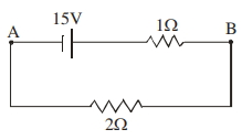
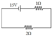
For the network shown below, the value of $V_{B} - V_{A}$ is . . . . . . $V$.
A
$9$
B
$20$
C
$10$
D
$30$
Solution
(C) The circuit consists of a $15 \, V$ battery in series with a $1 \, \Omega$ resistor and a $2 \, \Omega$ resistor.
Total resistance $R_{eq} = 1 \, \Omega + 2 \, \Omega = 3 \, \Omega$.
The current $i$ flowing in the circuit is given by Ohm's law: $i = \frac{V}{R_{eq}} = \frac{15 \, V}{3 \, \Omega} = 5 \, A$.
To find $V_{B} - V_{A}$, we traverse the path from $A$ to $B$ through the upper branch.
Starting from $A$, we go through the battery (potential increases by $15 \, V$) and then through the $1 \, \Omega$ resistor (potential decreases by $i \times R = 5 \, A \times 1 \, \Omega = 5 \, V$).
Thus, $V_{B} = V_{A} + 15 \, V - 5 \, V = V_{A} + 10 \, V$.
Therefore, $V_{B} - V_{A} = 10 \, V$.
0 likes
View Solution492
MediumMCQ
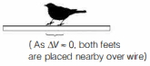
$A$ bird sitting on a single high tension wire does not get electrocuted because
A
the circuit is not complete
B
the resistance of the bird is very high
C
the capacitance of the bird is too small and the line frequency is too small
D
Both $A$ and $B$
Solution
(A) The correct option is $A$.
When a bird sits on a single high-tension wire,both of its feet are in contact with the same wire at points very close to each other. Since the wire is a good conductor,the potential difference between these two points is negligible (nearly zero).
According to Ohm's law,the current $I$ flowing through a conductor is given by $I = \frac{\Delta V}{R}$,where $\Delta V$ is the potential difference and $R$ is the resistance. Since $\Delta V \approx 0$,the current flowing through the bird's body is also approximately zero. Therefore,the circuit is not complete through the bird's body to the ground or another phase,and the bird does not get electrocuted.
0 likes
View Solution493
MediumMCQ
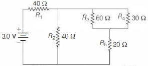
In the circuit shown below,the resistances are given (in $\Omega$) and the battery is assumed ideal with an electromotive force (emf) equal to $3.0 \, V$. The resistor that dissipates the most power is
A
$R_1$
B
$R_2$
C
$R_3$
D
$R_4$
Solution
(A) First,simplify the circuit. The resistors $R_3 = 60 \, \Omega$ and $R_4 = 30 \, \Omega$ are in parallel. Their equivalent resistance $R_p$ is given by:
$R_p = \frac{60 \times 30}{60 + 30} = \frac{1800}{90} = 20 \, \Omega$.
This combination is in series with $R_5 = 20 \, \Omega$,so the equivalent resistance of this branch is $R_{branch} = 20 + 20 = 40 \, \Omega$.
Now,this branch is in parallel with $R_2 = 40 \, \Omega$. The equivalent resistance of this parallel part is $R_{eq'} = \frac{40 \times 40}{40 + 40} = 20 \, \Omega$.
Finally,this is in series with $R_1 = 40 \, \Omega$. The total resistance of the circuit is $R_{total} = 40 + 20 = 60 \, \Omega$.
The total current from the battery is $I = \frac{V}{R_{total}} = \frac{3.0}{60} = 0.05 \, A$.
Power dissipated in $R_1$ is $P_1 = I^2 R_1 = (0.05)^2 \times 40 = 0.0025 \times 40 = 0.1 \, W$.
The current $I$ splits equally into the two parallel branches ($R_2$ and the branch containing $R_3, R_4, R_5$) because both have a resistance of $40 \, \Omega$. Thus,$I_2 = I_{branch} = 0.025 \, A$.
Power in $R_2$ is $P_2 = (0.025)^2 \times 40 = 0.000625 \times 40 = 0.025 \, W$.
In the branch with $R_3, R_4, R_5$,the current is $0.025 \, A$. Power in $R_5$ is $P_5 = (0.025)^2 \times 20 = 0.0125 \, W$.
The voltage across the parallel combination of $R_3$ and $R_4$ is $V_p = I_{branch} \times R_p = 0.025 \times 20 = 0.5 \, V$.
Power in $R_3$ is $P_3 = \frac{V_p^2}{R_3} = \frac{0.5^2}{60} = \frac{0.25}{60} \approx 0.0042 \, W$.
Power in $R_4$ is $P_4 = \frac{V_p^2}{R_4} = \frac{0.5^2}{30} = \frac{0.25}{30} \approx 0.0083 \, W$.
Comparing all powers,$P_1 = 0.1 \, W$ is the maximum. Therefore,$R_1$ dissipates the most power.
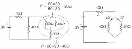
0 likes
View Solution494
AdvancedMCQ
$A$ student was trying to construct the circuit shown in the figure below marked $(a)$,but ended up constructing the circuit marked $(b)$. Realising her mistake,she corrected the circuit,but to her surprise,the output voltage (across $R$) did not change. The value of resistance $R$ is ............ $\Omega$
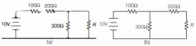
A
$100$
B
$150$
C
$200$
D
$300$
Solution
(A) For circuit $(a)$,the $100 \, \Omega$ and $200 \, \Omega$ resistors are in series,and this combination is in series with the parallel combination of $300 \, \Omega$ and $R$. However,looking at the diagram $(a)$,the $100 \, \Omega$ and $200 \, \Omega$ are in series,and the $300 \, \Omega$ and $R$ are in parallel with each other. The equivalent resistance is $R_{eq} = (100 + 200) + \frac{300R}{300+R} = 300 + \frac{300R}{300+R} = \frac{90000 + 600R}{300+R}$.
The total current is $I = \frac{10}{R_{eq}} = \frac{10(300+R)}{90000 + 600R}$.
The voltage across $R$ is $V_a = I \times \frac{300R}{300+R} = \frac{10(300+R)}{90000 + 600R} \times \frac{300R}{300+R} = \frac{3000R}{600R + 90000} = \frac{5R}{R + 150}$.
For circuit $(b)$,the $200 \, \Omega$ and $R$ are in series,and this is in parallel with $300 \, \Omega$. The equivalent resistance of this parallel part is $R_p = \frac{300(200+R)}{300+200+R} = \frac{60000 + 300R}{500+R}$.
The total resistance is $R_{eq} = 100 + R_p = 100 + \frac{60000 + 300R}{500+R} = \frac{50000 + 100R + 60000 + 300R}{500+R} = \frac{110000 + 400R}{500+R}$.
The total current is $I = \frac{10}{R_{eq}} = \frac{10(500+R)}{110000 + 400R}$.
The voltage across the parallel combination is $V_p = I \times R_p = \frac{10(500+R)}{110000 + 400R} \times \frac{60000 + 300R}{500+R} = \frac{600000 + 3000R}{110000 + 400R} = \frac{6000 + 30R}{1100 + 4R}$.
The voltage across $R$ is $V_b = V_p \times \frac{R}{200+R} = \frac{30(200+R)}{1100+4R} \times \frac{R}{200+R} = \frac{30R}{1100+4R}$.
Equating $V_a = V_b$: $\frac{5R}{R+150} = \frac{30R}{1100+4R} \Rightarrow \frac{1}{R+150} = \frac{6}{1100+4R} \Rightarrow 1100 + 4R = 6R + 900 \Rightarrow 2R = 200 \Rightarrow R = 100 \, \Omega$.
0 likes
View Solution495
MediumMCQ
In the circuit shown below, a student performing Ohm's law experiment accidentally connects the voltmeter and the ammeter as shown. The reading in the voltmeter will be close to .......... $V$.
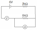
A
$0$
B
$4.8$
C
$6.0$
D
$1.2$
Solution
(C) The resistance of a voltmeter is very high (ideally infinite), and the resistance of an ammeter is very low (ideally zero).
When the ammeter is connected in parallel to the $8 \, k\Omega$ resistor, the ammeter acts as a short circuit across the $8 \, k\Omega$ resistor. Therefore, the effective resistance of this parallel combination is nearly $0 \, \Omega$.
Now, the circuit effectively consists of the $6 \, V$ battery in series with the $2 \, k\Omega$ resistor and the high-resistance voltmeter.
Since the resistance of the voltmeter is extremely high compared to the $2 \, k\Omega$ resistor, almost the entire potential difference of the battery drops across the voltmeter.
Therefore, the reading of the voltmeter will be nearly $6.0 \, V$.
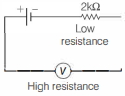
0 likes
View Solution496
DifficultMCQ
In the circuit shown,wire $1$ is of negligible resistance. Then,
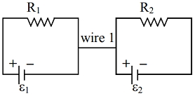
A
current will flow through wire $1$,if $\varepsilon_1 \neq \varepsilon_2$
B
current will flow through wire $1$,if $\frac{\varepsilon_1}{R_1} \neq \frac{\varepsilon_2}{R_2}$
C
current will flow through wire $1$,if $\frac{\varepsilon_1+\varepsilon_2}{(R_1+R_2)} \neq \frac{\varepsilon_1-\varepsilon_2}{(R_1-R_2)}$
D
no current will flow through wire $1$
Solution
(D) Consider the two loops separately. In the first loop,the current $i_1$ flows through the resistor $R_1$ and the cell $\varepsilon_1$. By Kirchhoff's voltage law,$i_1 = \frac{\varepsilon_1}{R_1}$.
Similarly,in the second loop,the current $i_2$ flows through the resistor $R_2$ and the cell $\varepsilon_2$. By Kirchhoff's voltage law,$i_2 = \frac{\varepsilon_2}{R_2}$.
Since each loop is a closed circuit independent of the other,the charge conservation principle implies that the current entering any junction must equal the current leaving it.
For the junction connecting the two loops to wire $1$,if we apply Kirchhoff's current law,the sum of currents must be zero. Since the loops are isolated from each other regarding current flow,no current can flow through the connecting wire $1$ to maintain the continuity of the individual loops. Thus,the current through wire $1$ is zero.
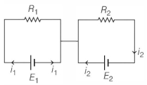
0 likes
View Solution497
AdvancedMCQ
$A$ light bulb of resistance $R = 16 \, \Omega$ is attached in series with an infinite resistor network with identical resistances $r$ as shown below. $A$ $10 \, V$ battery drives current in the circuit. Find the value of $r$ in $\Omega$ such that the bulb dissipates about $1 \, W$ of power.
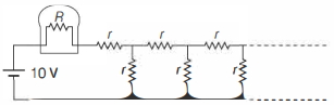
A
$14.8$
B
$29.6$
C
$7.4$
D
$3.7$
Solution
(A) Let the equivalent resistance of the infinite network be $x$. Adding or removing one repeating unit does not alter the resistance of an infinite network. Thus, the network can be represented as a series combination of $r$ and a parallel combination of $r$ and $x$.
$x = r + \frac{rx}{r+x}$
$x(r+x) = r(r+x) + rx$
$xr + x^2 = r^2 + rx + rx$
$x^2 - rx - r^2 = 0$
Using the quadratic formula $x = \frac{-b \pm \sqrt{b^2 - 4ac}}{2a}$:
$x = \frac{r \pm \sqrt{r^2 - 4(1)(-r^2)}}{2} = \frac{r \pm \sqrt{5r^2}}{2} = \frac{r(1 + \sqrt{5})}{2}$ (taking the positive root).
The power consumed by the bulb is $P = i^2 R = 1 \, W$.
$i^2 (16) = 1 \Rightarrow i^2 = \frac{1}{16} \Rightarrow i = 0.25 \, A$.
The total resistance of the circuit is $R_{total} = R + x = 16 + \frac{r(1 + \sqrt{5})}{2}$.
Using Ohm's law $V = i R_{total}$:
$10 = 0.25 \times (16 + \frac{r(1 + \sqrt{5})}{2})$
$40 = 16 + \frac{r(1 + 2.236)}{2}$
$24 = \frac{3.236r}{2} = 1.618r$
$r = \frac{24}{1.618} \approx 14.83 \, \Omega$.
Thus, the value of $r$ is approximately $14.8 \, \Omega$.
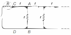
0 likes
View Solution498
DifficultMCQ
In the circuit shown,$n$-identical resistors $R$ are connected in parallel $(n > 1)$ and the combination is connected in series to another resistor $R_0$. In the adjoining circuit,$n$ resistors of resistance $R$ are all connected in series along with $R_0$. The batteries in both circuits are identical and the net power dissipated in the $n$ resistors in both circuits is the same. The ratio $R_0 / R$ is
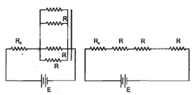
A
$1$
B
$n$
C
$n^2$
D
$1 / n$
Solution
(A) In case $I$ (parallel combination):
Total circuit resistance,$R_{\text{eq}, 1} = R_0 + \frac{R}{n} = \frac{n R_0 + R}{n}$.
Circuit current,$i_1 = \frac{E}{R_{\text{eq}, 1}} = \frac{n E}{n R_0 + R}$.
Power dissipated in the $n$ resistors,$P_1 = i_1^2 \cdot \left(\frac{R}{n}\right) = \left(\frac{n E}{n R_0 + R}\right)^2 \cdot \frac{R}{n} = \frac{n E^2 R}{(n R_0 + R)^2}$.
In case $II$ (series combination):
Total circuit resistance,$R_{\text{eq}, 2} = R_0 + n R$.
Circuit current,$i_2 = \frac{E}{R_{\text{eq}, 2}} = \frac{E}{R_0 + n R}$.
Power dissipated in the $n$ resistors,$P_2 = i_2^2 \cdot (n R) = \left(\frac{E}{R_0 + n R}\right)^2 \cdot n R = \frac{n E^2 R}{(R_0 + n R)^2}$.
Given $P_1 = P_2$:
$\frac{n E^2 R}{(n R_0 + R)^2} = \frac{n E^2 R}{(R_0 + n R)^2}$.
This implies $(n R_0 + R)^2 = (R_0 + n R)^2$.
Taking the square root,$n R_0 + R = R_0 + n R$ (since $R_0, R, n > 0$).
$(n - 1) R_0 = (n - 1) R$.
Since $n > 1$,we get $R_0 = R$,so $\frac{R_0}{R} = 1$.
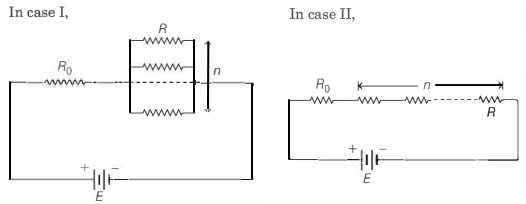
0 likes
View Solution499
MediumMCQ
In the following circuit,$1 \,\Omega$ resistor dissipates power $P$. If the resistor is replaced by $9 \,\Omega$,the power dissipated in it is
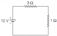
A
$P$
B
$3 P$
C
$9 P$
D
$\frac{P}{3}$
Solution
(A) In the given circuit,the $3 \,\Omega$ and $1 \,\Omega$ resistors are in series with a $10 \,V$ battery.
The equivalent resistance of the circuit is $R_{eq} = 3 \,\Omega + 1 \,\Omega = 4 \,\Omega$.
The current flowing through the circuit is $i = \frac{V}{R_{eq}} = \frac{10 \,V}{4 \,\Omega} = 2.5 \,A$.
The power dissipated in the $1 \,\Omega$ resistor is $P = i^2 R = (2.5)^2 \times 1 = 6.25 \,W$.
When the $1 \,\Omega$ resistor is replaced by a $9 \,\Omega$ resistor,the new equivalent resistance becomes $R'_{eq} = 3 \,\Omega + 9 \,\Omega = 12 \,\Omega$.
The new current in the circuit is $i' = \frac{10 \,V}{12 \,\Omega} = \frac{5}{6} \,A$.
The power dissipated in the $9 \,\Omega$ resistor is $P' = (i')^2 \times 9 = \left(\frac{5}{6}\right)^2 \times 9 = \frac{25}{36} \times 9 = \frac{25}{4} \,W = 6.25 \,W$.
Since $P = 6.25 \,W$ and $P' = 6.25 \,W$,we have $P' = P$.
0 likes
View Solution500
Advanced
Consider the two circuits $P$ and $Q$ shown below,which are used to measure the unknown resistance $R$. In each case,the resistance is estimated by using Ohm's law $R_{\text{est}} = \frac{V}{I}$,where $V$ and $I$ are the readings of the voltmeter and the ammeter,respectively. The meter resistances $R_V$ and $R_A$ are such that $R_A \ll R \ll R_V$. The internal resistance of the battery may be ignored. The absolute error in the estimate of the resistance is denoted by $\delta R = |R - R_{\text{est}}|$.
$(a)$ Express $\delta R_P$ in terms of the given resistance values.
$(b)$ Express $\delta R_Q$ in terms of the given resistance values.
$(c)$ For what value of $R$ will $\delta R_P \approx \delta R_Q$?
$(a)$ Express $\delta R_P$ in terms of the given resistance values.
$(b)$ Express $\delta R_Q$ in terms of the given resistance values.
$(c)$ For what value of $R$ will $\delta R_P \approx \delta R_Q$?
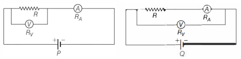
Solution
(D) In circuit $P$,the voltmeter is in parallel with $R$. The measured voltage $V$ is the voltage across $R$,but the ammeter measures the total current $I = I_R + I_V = \frac{V}{R} + \frac{V}{R_V}$.
Thus,$R_{\text{est}} = \frac{V}{I} = \frac{V}{V/R + V/R_V} = \frac{R R_V}{R + R_V} = R \left(1 + \frac{R}{R_V}\right)^{-1} \approx R \left(1 - \frac{R}{R_V}\right)$.
The error is $\delta R_P = |R - R_{\text{est}}| = |R - R(1 - R/R_V)| = \frac{R^2}{R_V}$.
$(b)$ In circuit $Q$,the ammeter is in series with $R$. The ammeter measures the current $I$ through $R$,but the voltmeter measures the voltage across both $R$ and the ammeter,$V = I(R + R_A)$.
Thus,$R_{\text{est}} = \frac{V}{I} = R + R_A$.
The error is $\delta R_Q = |R - R_{\text{est}}| = |R - (R + R_A)| = R_A$.
$(c)$ For $\delta R_P \approx \delta R_Q$,we have $\frac{R^2}{R_V} = R_A$,which implies $R^2 = R_A R_V$,or $R = \sqrt{R_A R_V}$.
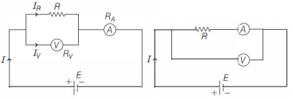
0 likes
View SolutionCurrent Electricity — Circuit Solving for current and Voltage · Frequently Asked Questions
1Are these Current Electricity questions useful for JEE and NEET?
Yes. All questions in this section are mapped to JEE Main and NEET exam patterns. Previous year questions from JEE Main, NEET, GUJCET and state-level exams are included with full solutions.
2Can I switch to Hindi or Gujarati for these questions?
Yes. Use the language tabs in the hero section or the sidebar to view the same questions and solutions in English, Hindi or Gujarati.
3How do I generate a question paper from this subtopic?
Use the Vedclass Exam Paper Generator — select the chapter and subtopic, set difficulty, and generate Sets A, B, C, D automatically. First 3 chapters of every subject are free.
Vedclass Products
For Students
Vedclass Test Series
Mock tests in real JEE/NEET style with performance analysis. 5-day free trial.
Start Free TrialFor Teachers
Exam Paper Generator
Generate Set A/B/C/D papers from this chapter in 2 minutes. 3 chapters free.
Try FreeFor Institutes
Online Exam Module
Live online exams with unlimited students, 360° analytics & white-label branding.
See DemoFor Teachers & Institutes
Generate a Current Electricity Exam Paper in 2 Minutes
Select subtopic & difficulty — Sets A, B, C, D auto-generated with No Repeat logic.
First 3 chapters of every subject are free — no payment required.