
A English
Mix Examples - Electricity Questions in English
Class 10 Science · Electricity · Mix Examples - Electricity
449+
Questions
English
Language
100%
With Solutions
Showing 50 of 449 questions in English
1
MediumMCQ
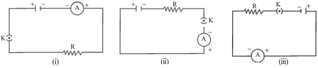
$A$ cell,a resistor,a key and an ammeter are arranged as shown in the circuit diagrams of the figure. The current recorded in the ammeter will be
A
The same in all the cases
B
maximum in $(i)$
C
maximum in $(ii)$
D
maximum in $(iii)$
Solution
(A) According to Ohm's Law,the current $I$ in a series circuit is given by $I = V/R$,where $V$ is the potential difference (voltage of the cell) and $R$ is the total resistance of the circuit.
In all three circuit diagrams $(i)$,$(ii)$,and $(iii)$,the components (cell,resistor,key,and ammeter) are connected in series.
Since the components are the same and they are connected in series,the total resistance $R$ and the total voltage $V$ remain constant in all three cases.
Therefore,the current $I$ flowing through the circuit will be the same in all three cases.
0 likes
View Solution2
MediumMCQ
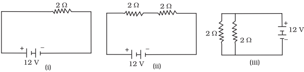
In the following circuits (Figure),heat produced in the resistor or combination of resistors connected to a $12\, V$ battery will be
A
minimum in case $(i)$
B
same in all the cases
C
maximum in case $(ii)$
D
maximum in case $(iii)$
Solution
(D) The heat produced in a circuit is given by the formula $H = \frac{V^2}{R} \times t$,where $V$ is the potential difference,$R$ is the equivalent resistance,and $t$ is the time.
Since $V = 12\, V$ is constant for all cases,the heat produced $H$ is inversely proportional to the equivalent resistance $R$ $(H \propto \frac{1}{R})$.
Case $(i)$: $A$ single resistor of $2\, \Omega$. Equivalent resistance $R_1 = 2\, \Omega$.
Case $(ii)$: Two resistors of $2\, \Omega$ each connected in series. Equivalent resistance $R_2 = 2\, \Omega + 2\, \Omega = 4\, \Omega$.
Case $(iii)$: Two resistors of $2\, \Omega$ each connected in parallel. Equivalent resistance $R_3 = \frac{2 \times 2}{2 + 2} = \frac{4}{4} = 1\, \Omega$.
Comparing the resistances: $R_3 (1\, \Omega) < R_1 (2\, \Omega) < R_2 (4\, \Omega)$.
Since $H \propto \frac{1}{R}$,the heat produced will be maximum where the resistance is minimum.
Therefore,the heat produced is maximum in case $(iii)$ because it has the lowest equivalent resistance $(1\, \Omega)$.
0 likes
View Solution3
EasyMCQ
Electrical resistivity of a given metallic wire depends upon
A
its length
B
its thickness
C
nature of the material
D
its shape
Solution
(C) The electrical resistivity $(\rho)$ of a material is an intrinsic property that depends only on the nature of the material and the temperature of the conductor.
It does not depend on the physical dimensions of the wire, such as its length, thickness (cross-sectional area), or shape.
While resistance $(R)$ depends on length and area $(R = \rho \frac{l}{A})$, resistivity $(\rho)$ remains constant for a given material at a specific temperature.
It does not depend on the physical dimensions of the wire, such as its length, thickness (cross-sectional area), or shape.
While resistance $(R)$ depends on length and area $(R = \rho \frac{l}{A})$, resistivity $(\rho)$ remains constant for a given material at a specific temperature.
0 likes
View Solution4
EasyMCQ
$A$ current of $1\, A$ is drawn by a filament of an electric bulb. The number of electrons passing through a cross-section of the filament in $16$ seconds would be roughly:
A
$10^{23}$
B
$10^{16}$
C
$10^{18}$
D
$10^{20}$
Solution
(D) The formula for electric current is $I = Q / t$,where $I$ is the current,$Q$ is the total charge,and $t$ is the time.
Given $I = 1\, A$ and $t = 16\, s$,the total charge $Q = I \times t = 1\, A \times 16\, s = 16\, C$.
The charge of a single electron is $e = 1.6 \times 10^{-19}\, C$.
The number of electrons $n$ is given by the formula $Q = n \times e$,which implies $n = Q / e$.
Substituting the values: $n = 16 / (1.6 \times 10^{-19}) = 10 / 10^{-19} = 10^{20}$.
Therefore,the number of electrons passing through the filament is $10^{20}$.
0 likes
View Solution5
MediumMCQ
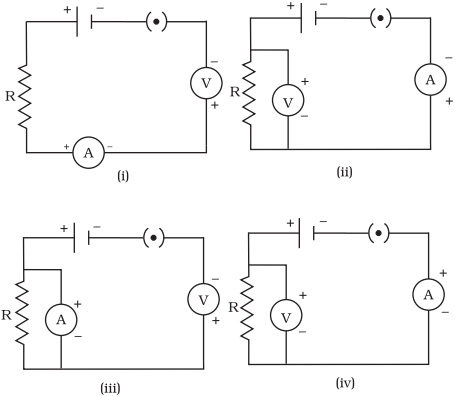
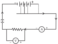
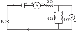
Identify the circuit (Figure) in which the electrical components have been properly connected.
A
$(ii)$
B
$(i)$
C
$(iii)$
D
$(iv)$
Solution
(D) To determine the correct circuit,we must follow these rules for connecting electrical components:
$1$. An ammeter $(A)$ must always be connected in series with the circuit component (resistor $R$) to measure the current flowing through it. Its positive terminal should be connected towards the positive terminal of the battery.
$2$. $A$ voltmeter $(V)$ must always be connected in parallel across the component (resistor $R$) whose potential difference is to be measured. Its positive terminal should be connected towards the positive terminal of the battery.
Evaluating the circuits:
- Circuit $(i)$: The voltmeter is connected in series,which is incorrect.
- Circuit $(ii)$: The ammeter is connected in parallel,which is incorrect.
- Circuit $(iii)$: The ammeter is connected in parallel,which is incorrect.
- Circuit $(iv)$: The ammeter is connected in series with the resistor,and the voltmeter is connected in parallel across the resistor. Both are connected with the correct polarity. Thus,this is the correctly connected circuit.
0 likes
View Solution6
MediumMCQ
What is the maximum resistance which can be made using five resistors each of $1/5 \ \Omega$ (in $Omega$)?
A
$0.2$
B
$1$
C
$5$
D
$10$
Solution
(B) To obtain the maximum resistance from a given set of resistors,they must be connected in series.
In a series connection,the equivalent resistance $(R_{eq})$ is the sum of individual resistances.
Given that there are $n = 5$ resistors,each with a resistance of $R = 1/5 \ \Omega$.
The formula for equivalent resistance in series is $R_{eq} = R_1 + R_2 + R_3 + R_4 + R_5$.
Substituting the values: $R_{eq} = 1/5 + 1/5 + 1/5 + 1/5 + 1/5 = 5 \times (1/5) = 1 \ \Omega$.
Therefore,the maximum resistance is $1 \ \Omega$.
0 likes
View Solution7
MediumMCQ
What is the minimum resistance which can be made using five resistors each of $1/5\,\Omega$?
A
$1/5\,\Omega$
B
$1/10\,\Omega$
C
$1/25\,\Omega$
D
$25\,\Omega$
Solution
(C) To obtain the minimum resistance from a given set of resistors,they must be connected in a parallel combination.
For $n$ resistors each of resistance $R$ connected in parallel,the equivalent resistance $R_{eq}$ is given by the formula:
$1/R_{eq} = 1/R_1 + 1/R_2 + 1/R_3 + 1/R_4 + 1/R_5$
Given $R = 1/5\,\Omega$ and $n = 5$:
$1/R_{eq} = 5 / (1/5) = 25$
Therefore,$R_{eq} = 1/25\,\Omega$.
For $n$ resistors each of resistance $R$ connected in parallel,the equivalent resistance $R_{eq}$ is given by the formula:
$1/R_{eq} = 1/R_1 + 1/R_2 + 1/R_3 + 1/R_4 + 1/R_5$
Given $R = 1/5\,\Omega$ and $n = 5$:
$1/R_{eq} = 5 / (1/5) = 25$
Therefore,$R_{eq} = 1/25\,\Omega$.
0 likes
View Solution8
EasyMCQ
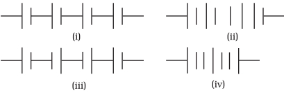
Which of the following combinations of cells in series (as shown in the figure) correctly represents the arrangement to obtain maximum potential?
A
$(i)$
B
$(ii)$
C
$(iii)$
D
$(iv)$
Solution
(A) To obtain the maximum potential difference from a combination of cells in series,the positive terminal of one cell must be connected to the negative terminal of the next cell.
In this arrangement,the potentials of the individual cells add up $(V_{total} = V_1 + V_2 + V_3 + ...)$.
Looking at the provided diagrams:
- In diagram $(i)$,the cells are connected such that the positive terminal of one is connected to the negative terminal of the next,which is the correct series arrangement.
- In the other diagrams,some cells are connected in reverse polarity,which would subtract from the total potential.
Therefore,$(i)$ is the correct representation.
0 likes
View Solution9
EasyMCQ
Which of the following represents voltage?
A
$\frac{\text{Work}}{\text{Current} \times \text{Time}}$
B
$\frac{\text{Work} \times \text{Time}}{\text{Current}}$
C
$\text{Work} \times \text{Electric charge}$
D
$\text{Work} \times \text{Electric charge} \times \text{Time}$
Solution
(A) Voltage $(V)$ is defined as the work done $(W)$ per unit charge $(Q)$ to move a charge between two points.
Mathematically,$V = \frac{W}{Q}$.
We know that electric current $(I)$ is the rate of flow of charge,given by $I = \frac{Q}{t}$,which implies $Q = I \times t$.
Substituting this value of $Q$ into the voltage formula,we get $V = \frac{W}{I \times t}$.
Therefore,voltage is represented by $\frac{\text{Work}}{\text{Current} \times \text{Time}}$.
0 likes
View Solution10
MediumMCQ
$A$ cylindrical conductor of length $l$ and uniform area of cross-section $A$ has resistance $R$. Another conductor of length $2l$ and resistance $R$ of the same material has area of cross-section:
A
$A/2$
B
$2A$
C
$3A/2$
D
$3A$
Solution
(B) The resistance $R$ of a conductor is given by the formula $R = \rho \frac{l}{A}$,where $\rho$ is the resistivity of the material,$l$ is the length,and $A$ is the area of cross-section.
For the first conductor: $R = \rho \frac{l}{A}$.
For the second conductor,the length is $2l$,the resistance is $R$,and the material is the same (so $\rho$ remains constant). Let the new area be $A'$.
Then,$R = \rho \frac{2l}{A'}$.
Equating the two expressions for $R$: $\rho \frac{l}{A} = \rho \frac{2l}{A'}$.
Canceling $\rho$ and $l$ from both sides: $\frac{1}{A} = \frac{2}{A'}$.
Solving for $A'$,we get $A' = 2A$.
0 likes
View Solution11
MediumMCQ
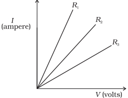
$A$ student carries out an experiment and plots the $V-I$ graph of three samples of nichrome wire with resistances $R_1, R_2$ and $R_3$ respectively (Figure). Which of the following is true?
A
$R_1 = R_2 = R_3$
B
$R_1 > R_2 > R_3$
C
$R_1 < R_2 < R_3$
D
$R_2 > R_3 > R_1$
Solution
(C) According to Ohm's law, $V = IR$, which implies $I = V/R$ or $R = V/I$.
In the given $I-V$ graph, the slope of the line represents $I/V$, which is equal to $1/R$.
Therefore, the slope of the graph is inversely proportional to the resistance $(Slope \propto 1/R)$.
From the figure, the slope of the line for $R_1$ is the greatest, followed by $R_2$, and then $R_3$ (i.e., $Slope_1 > Slope_2 > Slope_3$).
Since the slope is inversely proportional to resistance, a higher slope indicates a lower resistance.
Thus, $R_1 < R_2 < R_3$.
0 likes
View Solution12
MediumMCQ
If the current $I$ through a resistor is increased by $100\%$ (assume that temperature remains unchanged), the increase in power dissipated will be ........ $\%$
A
$100$
B
$200$
C
$400$
D
$300$
Solution
(D) The power dissipated in a resistor is given by the formula $P = I^2 R$, where $I$ is the current and $R$ is the resistance.
Initially, let the current be $I_1 = I$ and the power be $P_1 = I^2 R$.
When the current is increased by $100\%$, the new current $I_2$ becomes $I + 100\% \text{ of } I = I + I = 2I$.
The new power dissipated $P_2$ is $P_2 = (I_2)^2 R = (2I)^2 R = 4I^2 R = 4P_1$.
The increase in power is $P_2 - P_1 = 4P_1 - P_1 = 3P_1$.
The percentage increase in power is given by $\frac{P_2 - P_1}{P_1} \times 100\% = \frac{3P_1}{P_1} \times 100\% = 300\%$.
0 likes
View Solution13
EasyMCQ
The resistivity of a material does not change if:
A
the shape of the resistor is changed
B
the material is changed
C
the temperature is changed
D
both material and temperature are changed
Solution
(A) Resistivity $(\rho)$ is an intrinsic property of a material.
It depends only on the nature of the material and the temperature.
It does not depend on the physical dimensions (length, area of cross-section) or the shape of the resistor.
Therefore, if the shape of the resistor is changed, the resistance $(R)$ will change, but the resistivity $(\rho)$ remains constant.
0 likes
View Solution14
MediumMCQ
In an electrical circuit,three incandescent bulbs $A, B$ and $C$ of rating $40 \, W, 60 \, W$ and $100 \, W$ respectively are connected in parallel to an electric source. Which of the following is likely to happen regarding their brightness?
A
Brightness of all the bulbs will be the same
B
Brightness of bulb $B$ will be more than that of $A$
C
Brightness of bulb $A$ will be the maximum
D
Brightness of bulb $C$ will be less than that of $B$
Solution
(B) When bulbs are connected in parallel,the potential difference $(V)$ across each bulb remains the same.
The power consumed by a bulb is given by the formula $P = V^2 / R$.
Since $V$ is constant,the power consumed is directly proportional to the brightness of the bulb.
Bulb $C$ has the highest power rating $(100 \, W)$,followed by bulb $B$ $(60 \, W)$,and bulb $A$ $(40 \, W)$.
Therefore,the brightness of bulb $C$ will be the maximum,and the brightness of bulb $A$ will be the minimum.
Comparing the options,the brightness of bulb $B$ $(60 \, W)$ is indeed more than that of bulb $A$ $(40 \, W)$.
0 likes
View Solution15
MediumMCQ
In an electrical circuit,two resistors of $2\,\Omega$ and $4\,\Omega$ respectively are connected in series to a $6\,V$ battery. The heat dissipated by the $4\,\Omega$ resistor in $5\,s$ will be ........ $J$.
A
$5$
B
$10$
C
$20$
D
$30$
Solution
(C) Given: Resistors $R_1 = 2\,\Omega$ and $R_2 = 4\,\Omega$ are connected in series.
Voltage $V = 6\,V$.
Time $t = 5\,s$.
Total resistance $R_{eq} = R_1 + R_2 = 2\,\Omega + 4\,\Omega = 6\,\Omega$.
The current $I$ flowing through the circuit is $I = V / R_{eq} = 6\,V / 6\,\Omega = 1\,A$.
Since the resistors are in series,the same current $I = 1\,A$ flows through the $4\,\Omega$ resistor.
The heat dissipated $H$ is given by the formula $H = I^2 R t$.
Substituting the values: $H = (1)^2 \times 4 \times 5 = 1 \times 4 \times 5 = 20\,J$.
0 likes
View Solution16
MediumMCQ
An electric kettle consumes $1\, kW$ of electric power when operated at $220\, V$. $A$ fuse wire of what rating (in $A$) must be used for it?
A
$1$
B
$2$
C
$4$
D
$5$
Solution
(D) The power consumed by the electric kettle is $P = 1\, kW = 1000\, W$.
The voltage at which it operates is $V = 220\, V$.
Using the formula for electric power,$P = V \times I$,we can find the current $I$ as:
$I = P / V$
$I = 1000 / 220 \approx 4.54\, A$.
Since the current drawn is approximately $4.54\, A$,a fuse wire with a rating slightly higher than this value is required to prevent the circuit from breaking during normal operation.
Therefore,a fuse of $5\, A$ rating is the most appropriate choice among the given options.
0 likes
View Solution17
MediumMCQ
Two resistors of resistance $2 \,\Omega$ and $4 \,\Omega$ when connected to a battery will have:
A
same current flowing through them when connected in series
B
same current flowing through them when connected in parallel
C
same potential difference across them when connected in series
D
different potential difference across them when connected in parallel
Solution
(A) In a series circuit,the current flowing through all components is the same because there is only one path for the charge to flow.
Therefore,when two resistors of $2 \,\Omega$ and $4 \,\Omega$ are connected in series,the same current flows through both of them.
In a parallel circuit,the potential difference across each resistor is the same,but the current flowing through them depends on their individual resistance values $(I = V/R)$.
Thus,option $A$ is the correct statement.
0 likes
View Solution18
EasyMCQ
The unit of electric power may also be expressed as:
A
kilowatt hour
B
volt ampere
C
watt second
D
joule second
Solution
(B) Electric power $(P)$ is defined as the rate at which electrical energy is consumed or dissipated in an electric circuit.
Mathematically,$P = V \times I$,where $V$ is the potential difference measured in volts $(V)$ and $I$ is the electric current measured in amperes $(A)$.
Therefore,the $SI$ unit of power,the watt $(W)$,can also be expressed as the product of volts and amperes $(V \cdot A)$.
- Kilowatt hour $(kWh)$ is a unit of electrical energy.
- Watt second $(Ws)$ is also a unit of energy (since $Power \times Time = Energy$).
- Joule second $(Js)$ is a unit of action.
Thus,the correct expression for electric power is volt ampere.
0 likes
View Solution19
Medium
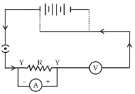
$A$ child has drawn the electric circuit to study Ohm's law as shown in the figure. His teacher told him that the circuit diagram needs correction. Study the circuit diagram and identify the errors,then describe the correct circuit configuration.
Solution
(N/A) The errors in the given circuit diagram are as follows:
$1$. The ammeter $(A)$ is connected in parallel with the resistor $(R)$,whereas it should be connected in series with the resistor.
$2$. The voltmeter $(V)$ is connected in series with the circuit,whereas it should be connected in parallel across the resistor $(R)$.
$3$. The polarity of the ammeter and voltmeter is incorrect in the diagram.
Correct circuit configuration:
$1$. Connect the ammeter $(A)$ in series with the resistor $(R)$.
$2$. Connect the voltmeter $(V)$ in parallel across the resistor $(R)$.
$3$. Ensure the positive terminal of the ammeter and voltmeter is connected towards the positive terminal of the battery,and the negative terminal is connected towards the negative terminal of the battery.
0 likes
View Solution20
DifficultMCQ
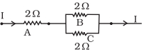
Three $2\,\Omega$ resistors,$A$,$B$,and $C$,are connected as shown in the figure. Each of them dissipates energy and can withstand a maximum power of $18\,W$ without melting. Find the maximum current (in $A$) that can flow through the circuit such that none of the resistors melt.
A
$3$
B
$4.5$
C
$1.5$
D
$6$
Solution
(A) The maximum power $P_{max}$ that each resistor can withstand is $18\,W$,and the resistance $R$ of each is $2\,\Omega$.
Using the formula $P = I^2R$,the maximum current $I_{max}$ that any individual resistor can withstand is:
$I_{max} = \sqrt{\frac{P_{max}}{R}} = \sqrt{\frac{18}{2}} = \sqrt{9} = 3\,A$.
In the given circuit,resistor $A$ is in series with the parallel combination of resistors $B$ and $C$.
The total current $I$ flows through resistor $A$. Therefore,the maximum current $I$ that can flow through the circuit is limited by the maximum current capacity of resistor $A$,which is $3\,A$.
If $I = 3\,A$,the current through $B$ and $C$ (which are equal) will be $I_B = I_C = \frac{I}{2} = 1.5\,A$.
Since $1.5\,A < 3\,A$,resistors $B$ and $C$ will not melt.
Thus,the maximum current that can flow through the circuit is $3\,A$.
0 likes
View Solution21
Medium
Should the resistance of an ammeter be low or high? Give reason.
Solution
(A) The resistance of an ammeter should be as low as possible,ideally $0 \ \Omega$.
An ammeter is connected in series with the circuit to measure the current flowing through it.
If the resistance of the ammeter is high,it will significantly reduce the total current in the circuit due to the increased total resistance $(R_{total} = R_{circuit} + R_{ammeter})$.
Therefore,to ensure the ammeter measures the true current without altering the circuit's behavior,its resistance must be negligible.
0 likes
View Solution22
Medium
Draw a circuit diagram of an electric circuit containing a cell,a key,an ammeter,a resistor of $2\,\Omega$ in series with a combination of two resistors ($4\,\Omega$ each) in parallel and a voltmeter across the parallel combination. Will the potential difference across the $2\,\Omega$ resistor be the same as that across the parallel combination of $4\,\Omega$ resistors? Give reason.
Solution
(A) Yes,the potential difference will be the same.
First,calculate the equivalent resistance of the parallel combination of two $4\,\Omega$ resistors:
$\frac{1}{R_p} = \frac{1}{4} + \frac{1}{4} = \frac{2}{4} = \frac{1}{2}$
So,$R_p = 2\,\Omega$.
Since the $2\,\Omega$ resistor is in series with the parallel combination (which also has an equivalent resistance of $2\,\Omega$),the same current $I$ flows through both. According to Ohm's Law $(V = IR)$,since the resistance values are equal $(2\,\Omega = 2\,\Omega)$ and the current $I$ is the same,the potential difference across both will be equal.
0 likes
View Solution23
Easy
How does the use of a fuse wire protect electrical appliances?
Solution
(N/A) fuse wire is made of a material with a low melting point.
When the current flowing through the circuit exceeds the safe limit (due to overloading or short-circuiting),the heat generated $(H = I^2Rt)$ causes the temperature of the fuse wire to rise rapidly.
Once the temperature reaches the melting point of the wire,it melts and breaks the circuit.
This disconnection stops the flow of current,thereby preventing damage to the electrical appliances.
0 likes
View Solution24
MediumMCQ
What is electrical resistivity? In a series electrical circuit comprising a resistor made up of a metallic wire, the ammeter reads $5\, A$. The reading of the ammeter decreases to half when the length of the wire is doubled. Why?
A
Due to change in cross-sectional area
B
Due to change in resistance
C
Due to change in voltage
D
Due to change in resistivity
Solution
(B) Electrical resistivity is the resistance offered by a unit length and unit cross-sectional area of a material. It is a characteristic property of the material.
According to the formula $R = \rho \frac{l}{A}$, where $R$ is resistance, $\rho$ is resistivity, $l$ is length, and $A$ is the cross-sectional area.
When the length of the wire is doubled $(l' = 2l)$, the resistance becomes $R' = \rho \frac{2l}{A} = 2R$.
Since the voltage $V$ remains constant in the circuit, according to Ohm's Law $(V = IR)$, the current $I$ is inversely proportional to resistance $(I = \frac{V}{R})$.
Therefore, when the resistance is doubled, the current becomes half of its original value, i.e., $I' = \frac{V}{2R} = \frac{I}{2} = \frac{5}{2} = 2.5\, A$.
0 likes
View Solution25
Easy
What is the commercial unit of electrical energy? Represent it in terms of joules.
Solution
(N/A) The commercial unit of electrical energy is the kilowatt-hour $(kWh)$.
To convert $1 \; kWh$ into joules $(J)$:
$1 \; kWh = 1 \; kW \times 1 \; h$
$1 \; kW = 1000 \; W = 1000 \; J/s$
$1 \; h = 60 \times 60 \; s = 3600 \; s$
Therefore,$1 \; kWh = 1000 \; J/s \times 3600 \; s = 3.6 \times 10^6 \; J$.
To convert $1 \; kWh$ into joules $(J)$:
$1 \; kWh = 1 \; kW \times 1 \; h$
$1 \; kW = 1000 \; W = 1000 \; J/s$
$1 \; h = 60 \times 60 \; s = 3600 \; s$
Therefore,$1 \; kWh = 1000 \; J/s \times 3600 \; s = 3.6 \times 10^6 \; J$.
0 likes
View Solution26
MediumMCQ
$A$ current of $1 \ A$ flows in a series circuit containing an electric lamp and a conductor of $5 \ \Omega$ when connected to a $10 \ V$ battery. Calculate the resistance of the electric lamp. Now,if a resistance of $10 \ \Omega$ is connected in parallel with this series combination,what change (if any) in the current flowing through the $5 \ \Omega$ conductor and the potential difference across the lamp will take place? Give reason.
A
Resistance of lamp is $5 \ \Omega$; no change in current or potential difference.
B
Resistance of lamp is $10 \ \Omega$; current through $5 \ \Omega$ conductor decreases.
C
Resistance of lamp is $5 \ \Omega$; current through $5 \ \Omega$ conductor increases.
D
Resistance of lamp is $2 \ \Omega$; potential difference across lamp changes.
Solution
(A) Step $1$: Calculate the resistance of the lamp.
In a series circuit,total resistance $R_{total} = V / I = 10 \ V / 1 \ A = 10 \ \Omega$.
Since $R_{total} = R_{lamp} + R_{conductor}$,we have $10 \ \Omega = R_{lamp} + 5 \ \Omega$.
Therefore,$R_{lamp} = 5 \ \Omega$.
Step $2$: Analyze the parallel connection.
When a $10 \ \Omega$ resistor is connected in parallel to the series combination,the potential difference across the series combination remains $10 \ V$ because the battery is connected directly across the parallel branches.
Since the potential difference across the series branch (lamp + $5 \ \Omega$ conductor) remains $10 \ V$,the current flowing through the series branch remains $I = V / R_{total} = 10 \ V / 10 \ \Omega = 1 \ A$.
Consequently,there will be no change in the current flowing through the $5 \ \Omega$ conductor,and there will be no change in the potential difference across the lamp.
0 likes
View Solution27
EasyMCQ
Why is parallel arrangement used in domestic wiring?
A
To increase the total resistance of the circuit.
B
To ensure each appliance receives the same potential difference.
C
To ensure the total current remains constant.
D
To prevent the flow of current in the circuit.
Solution
(B) In a parallel circuit,the potential difference across each electrical appliance remains the same as the source voltage.
This allows each appliance to operate independently at its rated voltage.
If one appliance is switched off or fails,the others continue to function normally.
Additionally,the total resistance of the circuit decreases,allowing for higher current capacity.
This allows each appliance to operate independently at its rated voltage.
If one appliance is switched off or fails,the others continue to function normally.
Additionally,the total resistance of the circuit decreases,allowing for higher current capacity.
0 likes
View Solution28
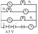
Medium
$B_1, B_2$ and $B_3$ are three identical bulbs connected as shown in the figure. When all three bulbs glow,a current of $3\,A$ is recorded by the ammeter $A$.
$(i)$ What happens to the glow of the other two bulbs when the bulb $B_1$ gets fused?
$(ii)$ What happens to the reading of $A_1, A_2, A_3$ and $A$ when the bulb $B_2$ gets fused?
$(iii)$ How much power is dissipated in the circuit when all three bulbs glow together?
$(i)$ What happens to the glow of the other two bulbs when the bulb $B_1$ gets fused?
$(ii)$ What happens to the reading of $A_1, A_2, A_3$ and $A$ when the bulb $B_2$ gets fused?
$(iii)$ How much power is dissipated in the circuit when all three bulbs glow together?
Solution
(N/A) $(i)$ Since the bulbs are connected in parallel,the potential difference across each bulb remains the same $(4.5\,V)$. Therefore,the glow of the bulbs $B_2$ and $B_3$ will remain unchanged when $B_1$ fuses.
$(ii)$ When $B_2$ fuses,the circuit branch containing $B_2$ becomes open. Thus,$A_2$ will show $0\,A$. The other two branches remain unaffected,so $A_1$ will show $1\,A$ and $A_3$ will show $1\,A$. The total current recorded by ammeter $A$ will be $1\,A + 0\,A + 1\,A = 2\,A$.
$(iii)$ The total power dissipated in the circuit is given by $P = V \times I$. Given $V = 4.5\,V$ and total current $I = 3\,A$,we have $P = 4.5\,V \times 3\,A = 13.5\,W$.
0 likes
View Solution29
Medium
Three incandescent bulbs of $100\, W$ each are connected in series in an electric circuit. In another circuit, another set of three bulbs of the same wattage are connected in parallel to the same source. Will the bulbs in the two circuits glow with the same brightness? Justify your answer.
Solution
(N/A) No, the bulbs will not glow with the same brightness.
$1$. In a series circuit, the total resistance is $R_{series} = R + R + R = 3R$. Since the voltage $V$ is constant, the current in each bulb is $I_{series} = V / (3R) = (1/3) \times (V/R)$.
$2$. In a parallel circuit, each bulb is connected directly to the source voltage $V$. Therefore, the current in each bulb is $I_{parallel} = V/R$.
$3$. Since the power dissipated by a bulb is $P = I^2R$, the power in the series circuit is $P_{series} = (V/3R)^2 \times R = V^2 / (9R)$, while in the parallel circuit, it is $P_{parallel} = (V/R)^2 \times R = V^2 / R$.
$4$. Because $P_{parallel} > P_{series}$, the bulbs in the parallel circuit will glow much more brightly than those in the series circuit.
0 likes
View Solution30
Easy
Three incandescent bulbs of $100\, W$ each are connected in series in an electric circuit. In another circuit,another set of three bulbs of the same wattage are connected in parallel to the same source. Now,if one bulb in both the circuits gets fused,will the rest of the bulbs continue to glow in each circuit? Give reasons.
Solution
(N/A) $1$. In the series circuit,the bulbs are connected in a single path. When one bulb fuses,the filament breaks,creating an open circuit. Consequently,the flow of current stops entirely,and all the remaining bulbs will stop glowing.
$2$. In the parallel circuit,each bulb is connected across the same potential difference independently. If one bulb fuses,it only affects its own branch. The other two bulbs remain connected to the source and will continue to glow with the same brightness as before.
$2$. In the parallel circuit,each bulb is connected across the same potential difference independently. If one bulb fuses,it only affects its own branch. The other two bulbs remain connected to the source and will continue to glow with the same brightness as before.
0 likes
View Solution31
Medium
State Ohm's law. How can it be verified experimentally? Does it hold good under all conditions? Comment.
Solution
(N/A) Ohm's law states that the current $I$ flowing through a conductor is directly proportional to the potential difference $V$ across its ends,provided the temperature and other physical conditions remain constant. Mathematically,$V \propto I$ or $V = IR$,where $R$ is the resistance of the conductor.
Experimental Verification:
$1$. Set up a circuit consisting of a resistor,an ammeter in series,a voltmeter in parallel across the resistor,a battery,and a rheostat.
$2$. Adjust the rheostat to change the current in the circuit and record the corresponding readings of the ammeter $(I)$ and voltmeter $(V)$.
$3$. Plot a graph of $V$ (y-axis) versus $I$ (x-axis). $A$ straight line passing through the origin confirms Ohm's law.
Limitations:
Ohm's law does not hold under all conditions. It is not applicable to non-ohmic devices like diodes,transistors,and vacuum tubes,where the $V-I$ relationship is non-linear. Additionally,for ohmic conductors,if the temperature changes significantly due to heating,the resistance $R$ changes,and the law may not hold strictly.
0 likes
View Solution32
Medium
What is the electrical resistivity of a material? What is its $SI$ unit? Describe an experiment to study the factors on which the resistance of a conducting wire depends.
Solution
(N/A) Electrical resistivity is defined as the resistance offered by a material of unit length and unit cross-sectional area. Mathematically,$R = \rho (l/A)$,where $\rho$ is the resistivity. Its $SI$ unit is ohm-metre $(\Omega \, m)$. To study the factors affecting resistance: $1$. Take a battery,an ammeter,a plug key,and nichrome wires of different lengths but same thickness. $2$. Connect the wire in the circuit and measure the current using the ammeter. $3$. Observe that resistance increases with the length of the wire $(R \propto l)$. $4$. Repeat the experiment using wires of the same length but different cross-sectional areas. $5$. Observe that resistance decreases as the area of cross-section increases $(R \propto 1/A)$.
0 likes
View Solution33
Medium
How will you infer with the help of an experiment that the same current flows through every part of the circuit containing three resistances in series connected to a battery?
Solution
(N/A) To demonstrate that the same current flows through every part of a series circuit,follow these steps:
$1$. Connect three resistors $(R_1, R_2, R_3)$ in series with a battery,an ammeter,and a plug key.
$2$. Place the ammeter at different positions in the circuit: first between the battery and the first resistor,then between the resistors,and finally after the last resistor.
$3$. Observe the reading of the ammeter in each position.
$4$. You will notice that the ammeter shows the same reading in all positions.
$5$. Conclusion: Since the ammeter measures the current flowing through the circuit,the identical readings confirm that the same amount of current flows through every component in a series circuit.
0 likes
View Solution34
MediumMCQ
How will you conclude that the same potential difference (voltage) exists across three resistors connected in a parallel arrangement to a battery?
A
By measuring the current through each resistor.
B
By measuring the potential difference across each resistor using a voltmeter connected in parallel.
C
By measuring the total resistance of the circuit.
D
By measuring the power consumed by each resistor.
Solution
(B) To conclude that the same potential difference exists across three resistors connected in parallel,follow these steps:
$1$. Connect three resistors $R_1, R_2,$ and $R_3$ in parallel across a battery of voltage $V$.
$2$. Connect a voltmeter in parallel across each resistor individually.
$3$. Observe the reading of the voltmeter for each resistor.
$4$. You will find that the voltmeter reading is the same for all three resistors,which is equal to the voltage $V$ of the battery.
$5$. This confirms that in a parallel circuit,the potential difference across each branch remains constant.
0 likes
View Solution35
Medium
What is Joule's heating effect? How can it be demonstrated experimentally? List its four applications in daily life.
Solution
(N/A) Joule's heating effect states that when an electric current $I$ flows through a conductor of resistance $R$ for time $t$,the heat $H$ produced is given by the formula $H = I^2Rt$.
Experimental demonstration: Connect a resistor of known resistance $R$ in series with an ammeter,a battery,and a plug key. Connect a voltmeter in parallel across the resistor. Measure the current $I$ and potential difference $V$ across the resistor. The heat produced can be calculated by measuring the temperature rise in a known mass of water or by using the formula $H = VIt$.
Applications in daily life:
$1$. Electric iron
$2$. Electric toaster
$3$. Electric heater
$4$. Electric kettle
0 likes
View Solution36
Medium
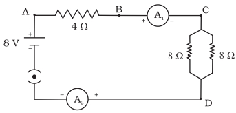
Find out the following in the electric circuit given in the figure:
$(a)$ Effective resistance of two $8\,\Omega$ resistors in the combination.
$(b)$ Current flowing through the $4\,\Omega$ resistor.
$(c)$ Potential difference across the $4\,\Omega$ resistor.
$(d)$ Power dissipated in the $4\,\Omega$ resistor.
$(e)$ Difference in ammeter readings,if any.
$(a)$ Effective resistance of two $8\,\Omega$ resistors in the combination.
$(b)$ Current flowing through the $4\,\Omega$ resistor.
$(c)$ Potential difference across the $4\,\Omega$ resistor.
$(d)$ Power dissipated in the $4\,\Omega$ resistor.
$(e)$ Difference in ammeter readings,if any.
Solution
(N/A) The two $8\,\Omega$ resistors are in parallel. Their effective resistance $R_p$ is given by:
$R_p = \frac{R_1 \times R_2}{R_1 + R_2} = \frac{8 \times 8}{8 + 8} = \frac{64}{16} = 4\,\Omega$.
$(b)$ The total resistance of the circuit $R_{eq} = R_{series} + R_p = 4\,\Omega + 4\,\Omega = 8\,\Omega$. The total current $I$ flowing through the circuit is $I = \frac{V}{R_{eq}} = \frac{8\,V}{8\,\Omega} = 1\,A$. Since the $4\,\Omega$ resistor is in series with the rest of the circuit,the current flowing through it is $1\,A$.
$(c)$ The potential difference $V$ across the $4\,\Omega$ resistor is $V = I \times R = 1\,A \times 4\,\Omega = 4\,V$.
$(d)$ The power dissipated $P$ in the $4\,\Omega$ resistor is $P = I^2 R = (1\,A)^2 \times 4\,\Omega = 4\,W$.
$(e)$ There is no difference in the ammeter readings. In a series circuit,the same amount of current flows through every component.
0 likes
View Solution37
EasyMCQ
If the charge on an electron is $1.6 \times 10^{-19} \text{ C}$,find the approximate number of electrons in $1 \text{ C}$.
A
$6.25 \times 10^{18}$
B
$6 \times 10^{18}$
C
$1.6 \times 10^{19}$
D
$6.25 \times 10^{17}$
Solution
(A) The quantization of electric charge is given by the formula $q = ne$,where $q$ is the total charge,$n$ is the number of electrons,and $e$ is the elementary charge.
Given $q = 1 \text{ C}$ and $e = 1.6 \times 10^{-19} \text{ C}$.
To find the number of electrons $(n)$,we rearrange the formula: $n = q / e$.
Substituting the values: $n = 1 / (1.6 \times 10^{-19}) = 10^{19} / 1.6 = 6.25 \times 10^{18}$.
Therefore,there are approximately $6.25 \times 10^{18}$ electrons in $1 \text{ C}$ of charge.
0 likes
View Solution38
Easy
List any two factors on which the resistance of a conductor depends.
Solution
(N/A) The resistance $(R)$ of a conductor depends on the following factors:
$1$. Length of the conductor $(l)$: Resistance is directly proportional to the length of the conductor $(R \propto l)$.
$2$. Area of cross-section $(A)$: Resistance is inversely proportional to the area of cross-section of the conductor $(R \propto 1/A)$.
$3$. Nature of the material: Resistance depends on the resistivity $(\rho)$ of the material.
$4$. Temperature: Resistance of a conductor changes with a change in temperature.
0 likes
View Solution39
Easy
Mention one reason why tungsten is used for making the filament of an electric lamp.
Solution
(N/A) Tungsten is used for making the filament of an electric lamp because it has a very high melting point (approximately $3380 ^\circ C$), which allows it to glow at high temperatures without melting. Additionally, it has a high resistivity, which helps in generating sufficient heat when an electric current passes through it.
0 likes
View Solution40
EasyMCQ
Calculate the number of electrons constituting one coulomb of charge. (Charge on one electron $= 1.6 \times 10^{-19} \text{ C}$)
A
$6.25 \times 10^{18}$
B
$1.6 \times 10^{19}$
C
$6.25 \times 10^{17}$
D
$1.6 \times 10^{18}$
Solution
(A) The total charge $Q$ is given as $1 \text{ C}$.
The charge on a single electron $e$ is $1.6 \times 10^{-19} \text{ C}$.
Using the quantization of charge formula, $Q = ne$, where $n$ is the number of electrons.
Therefore, $n = Q / e$.
$n = 1 \text{ C} / (1.6 \times 10^{-19} \text{ C})$.
$n = 1 / 1.6 \times 10^{19}$.
$n = 0.625 \times 10^{19}$.
$n = 6.25 \times 10^{18}$ electrons.
0 likes
View Solution41
Easy
$(a)$ Name the instrument/device used to measure electric current in a circuit.
$(b)$ How is an ammeter connected in a circuit to measure current flowing through it?
$(b)$ How is an ammeter connected in a circuit to measure current flowing through it?
Solution
(N/A) The instrument used to measure electric current in a circuit is called an $Ammeter$.
$(b)$ An $Ammeter$ is always connected in $series$ with the component or circuit through which the current is to be measured. This ensures that the total current flowing through the circuit passes through the $Ammeter$.
$(b)$ An $Ammeter$ is always connected in $series$ with the component or circuit through which the current is to be measured. This ensures that the total current flowing through the circuit passes through the $Ammeter$.
0 likes
View Solution42
Easy
In an electric circuit,state the relationship between the direction of conventional current and the direction of flow of electrons.
Solution
(N/A) The direction of conventional current is defined as the direction in which positive charges would move. Since electrons are negatively charged,they flow in the direction opposite to the conventional current. Therefore,the direction of conventional current is opposite to the direction of flow of electrons.
0 likes
View Solution43
EasyMCQ
How does the resistivity of alloys compare with those of pure metals from which they may have been formed?
A
Alloys have lower resistivity.
B
Alloys have higher resistivity.
C
Alloys have the same resistivity.
D
Resistivity is independent of the composition.
Solution
(B) The resistivity of an alloy is generally much higher than that of its constituent pure metals.
This occurs because the crystal lattice of an alloy is distorted by the presence of different types of atoms,which increases the scattering of electrons,thereby increasing the electrical resistance.
This occurs because the crystal lattice of an alloy is distorted by the presence of different types of atoms,which increases the scattering of electrons,thereby increasing the electrical resistance.
0 likes
View Solution44
Easy
Write the $SI$ unit of resistivity.
Solution
(A) The $SI$ unit of resistivity is the ohm-metre, denoted as $\Omega \cdot m$.
Resistivity $(\rho)$ is defined by the formula $R = \rho \frac{l}{A}$, where $R$ is resistance, $l$ is length, and $A$ is the cross-sectional area.
Rearranging for resistivity gives $\rho = \frac{R \cdot A}{l}$.
Substituting the $SI$ units: $\Omega \cdot \frac{m^2}{m} = \Omega \cdot m$.
Resistivity $(\rho)$ is defined by the formula $R = \rho \frac{l}{A}$, where $R$ is resistance, $l$ is length, and $A$ is the cross-sectional area.
Rearranging for resistivity gives $\rho = \frac{R \cdot A}{l}$.
Substituting the $SI$ units: $\Omega \cdot \frac{m^2}{m} = \Omega \cdot m$.
0 likes
View Solution45
Easy
State a difference between the wire used in the element of an electric heater and in a fuse wire.
Solution
(N/A) The wire used in the element of an electric heater is made of an alloy (like Nichrome) which has a very high resistance and a high melting point,allowing it to produce heat without melting. In contrast,a fuse wire is made of a material with a low melting point and appropriate resistance,designed to melt and break the circuit when the current exceeds a safe limit.
0 likes
View Solution46
EasyMCQ
Power of a lamp is $60\, W$. Find the energy in joules consumed by it in $1\, s$. (in $, J$)
A
$60$
B
$30$
C
$120$
D
$1$
Solution
(A) The formula for energy consumed is given by $E = P \times t$,where $P$ is power and $t$ is time.
Given: Power $(P)$ = $60\, W$,Time $(t)$ = $1\, s$.
Substituting the values: $E = 60\, W \times 1\, s = 60\, J$.
Therefore,the energy consumed is $60\, J$.
Given: Power $(P)$ = $60\, W$,Time $(t)$ = $1\, s$.
Substituting the values: $E = 60\, W \times 1\, s = 60\, J$.
Therefore,the energy consumed is $60\, J$.
0 likes
View Solution47
EasyMCQ
Which particles are responsible for the flow of current in conductors?
A
Protons
B
Electrons
C
Neutrons
D
Positrons
Solution
(B) In metallic conductors,the flow of electric current is primarily due to the movement of free electrons. These electrons are negatively charged particles that move through the crystal lattice of the conductor when an external electric field is applied.
0 likes
View Solution48
Easy
Define electrostatic potential at a point.
Solution
(N/A) The electrostatic potential at a point in an electric field is defined as the amount of work done in moving a unit positive charge from infinity to that specific point against the electrostatic force.
0 likes
View Solution49
EasyMCQ
What is the $SI$ unit of electric potential?
A
Ampere
B
Volt
C
Ohm
D
Watt
Solution
(B) The $SI$ unit of electric potential is the volt $(V)$.
It is defined as the amount of work done in moving a unit positive charge from infinity to a point in an electric field.
It is defined as the amount of work done in moving a unit positive charge from infinity to a point in an electric field.
0 likes
View Solution50
Easy
Write the mathematical expression for electric potential.
Solution
(N/A) The electric potential $(V)$ at a point in an electric field is defined as the amount of work $(W)$ done in moving a unit positive charge $(q)$ from infinity to that point.
Mathematically,it is expressed as:
$V = \frac{W}{q}$
Where:
$V$ = Electric potential
$W$ = Work done
$q$ = Charge
Mathematically,it is expressed as:
$V = \frac{W}{q}$
Where:
$V$ = Electric potential
$W$ = Work done
$q$ = Charge
0 likes
View SolutionElectricity — Mix Examples - Electricity · Frequently Asked Questions
1Are these Electricity questions useful for JEE and NEET?
Yes. All questions in this section are mapped to JEE Main and NEET exam patterns. Previous year questions from JEE Main, NEET, GUJCET and state-level exams are included with full solutions.
2Can I switch to Hindi or Gujarati for these questions?
Yes. Use the language tabs in the hero section or the sidebar to view the same questions and solutions in English, Hindi or Gujarati.
3How do I generate a question paper from this subtopic?
Use the Vedclass Exam Paper Generator — select the chapter and subtopic, set difficulty, and generate Sets A, B, C, D automatically. First 3 chapters of every subject are free.
Vedclass Products
For Students
Vedclass Test Series
Mock tests in real JEE/NEET style with performance analysis. 5-day free trial.
Start Free TrialFor Teachers
Exam Paper Generator
Generate Set A/B/C/D papers from this chapter in 2 minutes. 3 chapters free.
Try FreeFor Institutes
Online Exam Module
Live online exams with unlimited students, 360° analytics & white-label branding.
See DemoFor Teachers & Institutes
Generate a Electricity Exam Paper in 2 Minutes
Select subtopic & difficulty — Sets A, B, C, D auto-generated with No Repeat logic.
First 3 chapters of every subject are free — no payment required.