
A English
Mix Examples - Magnetic Effects of Electric Current Questions in English
Class 10 Science · Magnetic Effects of Electric Current · Mix Examples - Magnetic Effects of Electric Current
332+
Questions
English
Language
100%
With Solutions
Showing 50 of 332 questions in English
201
Medium
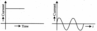
In our daily life,we use two types of electric current whose current-time graphs are given below:
$(i)$ Name the type of current in two cases.
$(ii)$ Identify any one source for each type of current.
$(iii)$ What is the frequency of current in case $(b)$ in our country?
$(iv)$ On the basis of these graphs,list two differences between the two currents.
$(v)$ Out of the two,which one is used in transmitting electric power over long distances and why?
Solution
(N/A) $(i)$ $(a)$ Direct current $(DC)$
$(b)$ Alternating current $(AC)$
$(ii)$ Source of direct current: Battery or cell. Source of alternating current: $AC$ generator or power plant.
$(iii)$ The frequency of $AC$ in our country is $50 \, Hz$.
$(iv)$ Two differences between the two currents are:
$1$. The magnitude of $DC$ remains constant with time,whereas the magnitude of $AC$ changes continuously with time.
$2$. The direction of $DC$ remains fixed,whereas the direction of $AC$ reverses periodically.
$(v)$ Alternating current $(AC)$ is used for transmitting electric power over long distances because it can be stepped up or down using transformers,which significantly reduces energy loss during transmission compared to $DC$.
0 likes
View Solution202
Medium
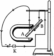
$(a)$ Describe an experiment with a diagram to show that force is exerted on a current-carrying conductor when placed perpendicular in a magnetic field.
$(b)$ How will this force change if the current in the conductor is increased?
$(c)$ Name a device that uses the above principle.
$(b)$ How will this force change if the current in the conductor is increased?
$(c)$ Name a device that uses the above principle.
Solution
(N/A) Experiment: Take a small aluminum rod $AB$ suspended horizontally from a stand by two connecting wires. Place a strong horseshoe magnet in such a way that the rod lies between the two poles with the magnetic field directed vertically upwards. Connect the ends of the rod in series with a battery,a key,and a rheostat. When current is passed through the rod from $B$ to $A$,the rod gets displaced. This displacement shows that a force is exerted on the current-carrying conductor when placed in a magnetic field.
$(b)$ The force acting on the conductor is directly proportional to the current flowing through it $(F \propto I)$. Therefore,if the current in the conductor is increased,the force acting on it will also increase,resulting in a larger displacement of the rod.
$(c)$ An electric motor is a device that works on this principle.
0 likes
View Solution203
Medium
$(a)$ Which effect of the electric current is utilised in the working of an electrical fuse?
$(b)$ Is a fuse connected in series or in parallel in a household circuit?
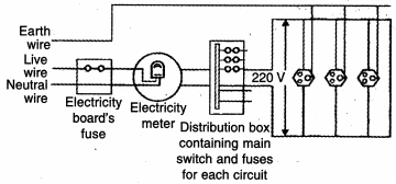
$(c)$ Draw a schematic labelled diagram of a domestic circuit which has a provision of a main fuse,meter,one light bulb,and a switch socket.
$(b)$ Is a fuse connected in series or in parallel in a household circuit?
$(c)$ Draw a schematic labelled diagram of a domestic circuit which has a provision of a main fuse,meter,one light bulb,and a switch socket.
Solution
(N/A) The heating effect of electric current is utilised in the working of an electrical fuse. When the current exceeds the safe limit,the wire melts due to excessive heat,breaking the circuit.
$(b)$ $A$ fuse is always connected in series with the live wire in a household circuit so that it can break the circuit if the current becomes too high.
$(c)$ The schematic diagram of a domestic circuit is provided below.
$(b)$ $A$ fuse is always connected in series with the live wire in a household circuit so that it can break the circuit if the current becomes too high.
$(c)$ The schematic diagram of a domestic circuit is provided below.
0 likes
View Solution204
Medium
Answer the following questions:
$(i)$ What is the direction of magnetic field lines outside a bar-magnet?
$(ii)$ Why two magnetic field lines cannot intersect each other?
$(iii)$ What is indicated by crowding of magnetic field lines in a given region?
$(iv)$ What is the frequency of $AC$ in India?
$(v)$ State one advantage of $AC$ over $DC$.
Solution
(N/A) $(i)$ Outside a bar magnet,the direction of magnetic field lines is from the North pole to the South pole.
$(ii)$ Two magnetic field lines cannot intersect each other because if they did,it would mean that at the point of intersection,the compass needle would point towards two different directions simultaneously,which is physically impossible.
$(iii)$ The crowding of magnetic field lines in a given region indicates that the magnetic field is stronger in that region.
$(iv)$ The frequency of $AC$ in India is $50 \, Hz$.
$(v)$ One major advantage of $AC$ over $DC$ is that $AC$ can be transmitted over long distances without significant loss of electrical energy.
0 likes
View Solution205
Medium
$(a)$ $A$ coil of insulated copper wire is connected to a galvanometer. What will happen if a bar magnet is:
$(i)$ pushed into the coil with its north pole entering first?
$(ii)$ withdrawn from inside the coil?
$(iii)$ held stationary inside the coil?
$(b)$ Name the above phenomenon and mention the name of the scientist who discovered it. State the law that relates the direction of current in the coil with the direction of motion of the magnet.
Solution
(D) $(i)$ $A$ momentary deflection occurs in the galvanometer due to the change in magnetic flux linked with the coil.
$(ii)$ $A$ momentary deflection occurs in the opposite direction because the change in magnetic flux is reversed.
$(iii)$ No deflection occurs because there is no change in magnetic flux when the magnet is stationary.
$(b)$ The phenomenon is called Electromagnetic Induction. It was discovered by Michael Faraday. The law that relates the direction of induced current to the direction of motion of the magnet is Fleming's Right-Hand Rule. It states that if you stretch the thumb,forefinger,and middle finger of your right hand such that they are mutually perpendicular,then the thumb points in the direction of motion of the conductor (or magnet),the forefinger points in the direction of the magnetic field,and the middle finger points in the direction of the induced current.
0 likes
View Solution206
Medium
$(a)$ When do we state that an electrical appliance is earthed? Mention the function of the earth wire in electric lines. Why is it necessary to earth electric appliances having a metallic body?
$(b)$ Explain what is short-circuiting and overloading in an electric supply.
$(b)$ Explain what is short-circuiting and overloading in an electric supply.
Solution
(N/A) An electrical appliance is said to be earthed when its metallic body is connected to a metal wire which is buried deep inside the earth. The function of the earth wire is to provide a low-resistance path for the current to flow into the ground in case of a leakage,thereby preventing electric shocks. It is necessary to earth appliances with metallic bodies because if a live wire touches the metal casing,the current flows to the earth instead of passing through the user,thus ensuring safety.
$(b)$ $(i)$ Short-circuiting: This occurs when the live wire and the neutral wire come into direct contact with each other,leading to a sudden surge in current.
$(ii)$ Overloading: This occurs when too many electrical appliances are connected to a single socket or circuit,exceeding the rated capacity of the wires,which can cause overheating.
0 likes
View Solution207
Medium
$(a)$ Define electromagnetic induction.
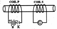
$(b)$ Two coils $P$ and $S$ are wound over the same iron core. Coil $P$ is connected to a battery and a key,and coil $S$ is connected to a galvanometer. Draw a suitable diagram of this arrangement and write your observations when:
$(i)$ current in the coil $P$ is started by closing the key.
$(ii)$ current continues to flow in coil $P$.
$(iii)$ current in coil $P$ is stopped by removing the key.
Explain the reason for such observations.
Solution
(N/A) Electromagnetic induction is the phenomenon of generating an electric current in a conductor by changing the magnetic field associated with it.
$(b)$ The diagram shows two coils $P$ (primary) and $S$ (secondary) wound on an iron core.
$(i)$ When the key is closed,the current in coil $P$ increases from zero to a maximum value. This causes a change in the magnetic field linked with coil $S$,resulting in a momentary deflection in the galvanometer.
$(ii)$ When the current flows steadily in coil $P$,the magnetic field associated with coil $S$ remains constant. Since there is no change in the magnetic flux,there is no induced current,and the galvanometer shows zero deflection.
$(iii)$ When the key is removed,the current in coil $P$ decreases to zero. This causes a rapid change in the magnetic field linked with coil $S$,resulting in a momentary deflection in the galvanometer in the opposite direction.
0 likes
View Solution208
Medium
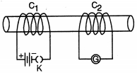
Two coils $C_{1}$ and $C_{2}$ are wrapped around a non-conducting cylinder. Coil $C_{1}$ is connected to a battery and a key $K$,and coil $C_{2}$ is connected to a galvanometer $G$. On pressing the key $K$,current starts flowing in the coil $C_{1}$. State your observations in the galvanometer for the following cases:
$(i)$ When key $K$ is pressed on.
$(ii)$ When current in the coil $C_{1}$ is switched off.
$(iii)$ When the current is passed continuously through coil $C_{1}$.
$(iv)$ Name and state the phenomenon responsible for the above observation. Write the name of the rule that is used to determine the direction of the induced current.
Solution
(N/A) $(i)$ The galvanometer will show a momentary deflection towards one side because the magnetic flux linked with coil $C_{2}$ changes as the current in $C_{1}$ increases from zero to a steady value.
$(ii)$ The galvanometer will show a momentary deflection in the direction opposite to the previous one because the magnetic flux linked with coil $C_{2}$ decreases as the current in $C_{1}$ drops to zero.
$(iii)$ The galvanometer will not show any deflection because the current in $C_{1}$ is steady,meaning the magnetic flux linked with $C_{2}$ remains constant.
$(iv)$ The phenomenon is electromagnetic induction. It is the process by which a changing magnetic field in one conductor induces an electromotive force $(EMF)$ and a current in another conductor placed near it. Fleming's right-hand rule is used to determine the direction of the induced current.
0 likes
View Solution209
Medium
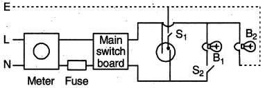
$(i)$ The given figure shows a domestic electric circuit. Study this circuit carefully. List any two errors in the circuit and justify your answer.
$(ii)$ Give one difference between the wires used in the element of an electric heater and in a fuse:
$(iii)$ List two advantages of parallel connection over series connection.
$(ii)$ Give one difference between the wires used in the element of an electric heater and in a fuse:
$(iii)$ List two advantages of parallel connection over series connection.
Solution
(N/A) $(i)$ Two errors are:
$(a)$ The fuse is incorrectly connected to the neutral wire $(N)$; it must be connected to the live wire $(L)$ to ensure safety by breaking the circuit during a fault.
$(b)$ Bulb $B_{2}$ is not connected to the neutral wire,meaning the circuit for $B_{2}$ is incomplete and it will not glow.
$(ii)$ The element of an electric heater is made of a material with a high melting point (like nichrome) to withstand high temperatures without melting. In contrast,a fuse wire is made of a material with a low melting point so that it melts and breaks the circuit when excessive current flows.
$(iii)$ Two advantages of parallel connection over series connection are:
$(a)$ Each appliance receives the same potential difference (voltage) as the power supply.
$(b)$ Each appliance has a separate switch,allowing it to be turned $ON$ or $OFF$ independently without affecting other appliances.
0 likes
View Solution210
Medium
$(i)$ Write the values of the following physical quantities in connection with domestic power supply in our country: $(a)$ potential difference between live wire and neutral wire.
$(b)$ frequency of $AC$.
$(ii)$ Explain the role of the following as safety measure in domestic electric appliances/circuits:
$(a)$ earth wire
$(b)$ fuse.
$(b)$ frequency of $AC$.
$(ii)$ Explain the role of the following as safety measure in domestic electric appliances/circuits:
$(a)$ earth wire
$(b)$ fuse.
Solution
(N/A) $(i)$
$(a) 220 \ V$
$(b) 50 \ Hz$
$(ii)$
$(a)$ Earth wire: The earth wire is a thick metal wire connected to a metal plate buried deep into the earth. It is used as a safety measure for appliances with a metallic body,$e.g.$,toasters,etc. The metallic body is connected to the earth wire,which provides a low-resistance conducting path for the current. It ensures that any leakage of current in the metallic body keeps its potential equal to that of the earth,preventing the user from getting a severe electric shock if touched.
$(b)$ Fuse: It is a piece of wire made of an alloy with a low melting point. If a current larger than the specified value flows through the circuit,the temperature of the fuse wire increases and it melts. This breaks the circuit and prevents the flow of an excessively high electric current in the device. In this way,a fuse of proper rating protects the appliance and the circuit from damage.
0 likes
View Solution211
Medium
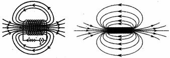
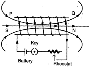
What is a solenoid? Draw the magnetic field lines for a solenoid and a bar magnet. Compare the two and state one similarity.
Solution
(N/A) solenoid is a coil of many circular turns of insulated copper wire wrapped closely in the shape of a cylinder.
The magnetic field lines for a solenoid and a bar magnet are shown in the provided image.
Comparison and Similarity:
$1$. Similarity: The pattern of magnetic field lines produced by a current-carrying solenoid is identical to that of a bar magnet. In both cases,the field lines emerge from the North pole and enter the South pole outside the magnet,and travel from South to North inside the magnet.
$2$. Comparison: $A$ solenoid acts as an electromagnet,meaning its magnetic field can be turned on or off by controlling the current,whereas a bar magnet is a permanent magnet with a constant magnetic field.
0 likes
View Solution212
Medium
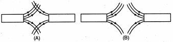
Magnetic field lines of two magnets are shown in figures $A$ and $B$. Select the figure that represents the correct pattern of the field lines. Give reasons for your answer. Also,name the poles of the magnets facing each other.
Solution
(B) Figure $(B)$ represents the correct pattern of magnetic field lines.
Reason: Magnetic field lines never intersect each other. If they were to intersect,it would mean that at the point of intersection,the magnetic field has two different directions at the same time,which is physically impossible.
The poles of the magnets facing each other are North poles,as the field lines are shown emerging from the magnets.
0 likes
View Solution213
Easy
You are given two identical-looking iron bars,out of which one of them is a magnet. Just using these two bars,how will you identify which one is a magnet?
Solution
(N/A) To identify the magnet,place one bar horizontally on a table and hold the other bar vertically. Bring the end of the vertical bar near the center of the horizontal bar.
$1$. If you feel a strong attraction,the vertical bar is the magnet.
$2$. If you feel no attraction or very weak attraction at the center,then the horizontal bar is the magnet.
Alternatively,move the vertical bar along the length of the horizontal bar. If the force of attraction is uniform,the vertical bar is the magnet. If the force is maximum at the ends and minimum at the center,the horizontal bar is the magnet.
0 likes
View Solution214
Medium
Describe an activity with a neat diagram to show the magnetic field lines around a bar magnet.
Solution
(N/A) $1$. Place a sheet of white paper on a drawing board and fix it using adhesive tape.
$2$. Place a bar magnet in the center of the paper and mark its boundary.
$3$. Place a small compass needle near the north pole of the magnet. The south pole of the compass needle will point towards the north pole of the magnet.
$4$. Mark the position of the two ends of the compass needle with a pencil.
$5$. Move the compass to a new position such that its south pole occupies the position previously occupied by the north pole.
$6$. Repeat this process step by step until you reach the south pole of the magnet.
$7$. Join the marked points with a smooth curve. This curve represents a magnetic field line.
$8$. Repeat the process to draw several such lines around the magnet.
0 likes
View Solution215
Medium
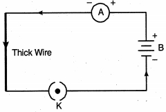
Describe an activity to show that the magnetic field produced by a given current in a wire decreases as the distance from the wire increases.
Solution
(N/A) To demonstrate this,we set up a circuit consisting of a battery $(12 \, V)$,a plug key $(K)$,an ammeter $(A)$,and a long thick copper wire as shown in the diagram.
$1$. Close the plug key $(K)$ to allow current to flow through the circuit.
$2$. Place a magnetic compass needle near the thick copper wire and observe its deflection.
$3$. Gradually move the compass needle away from the wire while keeping the current in the circuit constant.
$4$. We will observe that as the distance between the compass needle and the wire increases,the deflection of the needle decreases.
This observation confirms that the strength of the magnetic field produced by the current-carrying wire decreases as the distance from the wire increases.
0 likes
View Solution216
Medium
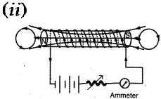
The diagram below shows a circuit containing a coil wound over a long and thin hollow cardboard tube. Copy the diagram and:
$(i)$ Show the polarity acquired by each face of the solenoid.
$(ii)$ Draw the magnetic field lines of force inside the coil and also show their direction.
$(iii)$ Mention two methods to increase the strength of the magnetic field inside the coil.
$(i)$ Show the polarity acquired by each face of the solenoid.
$(ii)$ Draw the magnetic field lines of force inside the coil and also show their direction.
$(iii)$ Mention two methods to increase the strength of the magnetic field inside the coil.
Solution
(N/A) $(i)$ Based on the direction of current flow,end $A$ acts as the North pole and end $B$ acts as the South pole.
$(ii)$ The magnetic field lines inside the solenoid are parallel to the axis of the solenoid,indicating a uniform magnetic field. The direction of the field lines is from the South pole to the North pole inside the coil.
$(iii)$ Two methods to increase the strength of the magnetic field inside the coil are:
$1$. Increase the magnitude of the current flowing through the coil.
$2$. Increase the number of turns in the coil or insert a soft iron core inside the solenoid.
0 likes
View Solution217
Medium
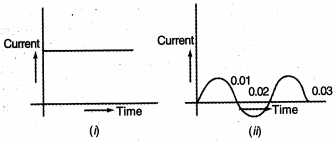
In the diagrams shown below:
$(i)$ Name the type of current in two cases.
$(ii)$ Identify any one source for each type of these currents.
$(iii)$ What is the frequency of current in case $(ii)$ in India?
$(iv)$ Use above graphs to write two differences between the current in two cases.
$(i)$ Name the type of current in two cases.
$(ii)$ Identify any one source for each type of these currents.
$(iii)$ What is the frequency of current in case $(ii)$ in India?
$(iv)$ Use above graphs to write two differences between the current in two cases.
Solution
(N/A) $(i)$ The current is direct current $(dc)$ in the first case and is alternating current $(ac)$ in the second case.
$(ii)$ $(a)$ Battery $(b)$ $ac$ generator.
$(iii)$ $50 \ Hz$.
$(iv)$
$(ii)$ $(a)$ Battery $(b)$ $ac$ generator.
$(iii)$ $50 \ Hz$.
$(iv)$
| $dc$ | $ac$ |
|---|---|
| Current always flows in the same direction. | Current changes magnitude and direction periodically. |
| Cannot be easily converted into $ac$. | Can be easily converted into $dc$. |
0 likes
View Solution218
Easy
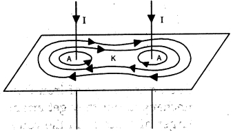
The following diagram shows two straight wires carrying current. Copy the diagram and draw the pattern of lines of force around them and mark their directions.
Solution
(N/A) According to the right-hand thumb rule,when current flows through a straight wire,the magnetic field lines form concentric circles around the wire.
Since both wires carry current in the same downward direction,the magnetic field lines around each wire will be in the clockwise direction.
As the lines of force from both wires interact,they form a combined pattern where the lines between the wires cancel each other out to some extent,resulting in the pattern shown in the figure below.
0 likes
View Solution219
Medium
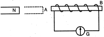
The diagram below shows a coil connected to a centre zero galvanometer $G$. The galvanometer shows a deflection to the right when the $N$ pole of a powerful magnet is moved to the right as shown.
$(i)$ Explain why the deflection occurs in the galvanometer.
$(ii)$ Does the direction of current in the coil appear clockwise or anticlockwise when viewed from end $A$?
$(iii)$ State the observation in $G$ when the coil is moved away from $N$.
$(iv)$ State the observation in $G$ when,both coil and the magnet,are moved to the right at the same speed.
Solution
(N/A) $(i)$ The deflection occurs due to the change in magnetic flux linked with the coil as the magnet moves. This change in magnetic flux induces an electromotive force $(emf)$ in the coil,which causes an induced current to flow through the galvanometer.
$(ii)$ According to Lenz's Law,the induced current will create a magnetic pole at end $A$ that opposes the approaching $N$ pole of the magnet. Thus,end $A$ acts as an $N$ pole. When viewed from end $A$,the direction of the current appears anticlockwise.
$(iii)$ When the coil is moved away from $N$,the magnetic flux linked with the coil decreases. This induces a current in the opposite direction,causing the galvanometer to show a deflection to the left.
$(iv)$ When both the coil and the magnet are moved to the right at the same speed,there is no relative motion between them. Consequently,there is no change in the magnetic flux linked with the coil,and the galvanometer shows no deflection (zero reading).
0 likes
View Solution220
Easy
State the energy change which takes place when a magnet is moved inside a coil having a galvanometer at its ends. Name this phenomenon.
Solution
(N/A) When a magnet is moved inside a coil,the mechanical work done in moving the magnet is converted into electrical energy,which is detected by the deflection in the galvanometer.
The phenomenon is known as electromagnetic induction.
The phenomenon is known as electromagnetic induction.
0 likes
View Solution221
Easy
You have just paid the electricity bill for your house.
$(i)$ What was it that your family consumed,for which you had to pay?
$(ii)$ In what unit was it measured?
$(i)$ What was it that your family consumed,for which you had to pay?
$(ii)$ In what unit was it measured?
Solution
(N/A) $(i)$ The family consumed electrical energy.
$(ii)$ The energy consumed was measured in kilowatt-hour $(kWh)$.
$(ii)$ The energy consumed was measured in kilowatt-hour $(kWh)$.
0 likes
View Solution222
Easy
Make a table with names of three electrical appliances used in your home in one column, their power, voltage rating, and approximate time for which each is used in one day in the other columns.
Solution
(N/A)
| Name of appliance | Power rating, Voltage rating, and Daily use |
|---|---|
| Fluorescent tube | $40 \, W, 220 \, V, 5 \, \text{hours}$ |
| Fan | $60 \, W, 220 \, V, 15 \, \text{hours}$ |
| Geyser | $2000 \, W, 220 \, V, 1.5 \, \text{hours}$ |
0 likes
View Solution223
Medium
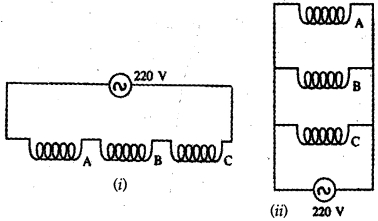
The diagram below shows two ways of connecting three bulbs $A, B$ and $C$ to a $220 \,V$ main in a room. Name the two arrangements. Which of them would you prefer for household electricity? Give two reasons.
Solution
(D) The arrangement shown in figure $(i)$ is a series arrangement. The arrangement in figure $(ii)$ is a parallel arrangement.
We would prefer the parallel arrangement for household electricity. The reasons are:
$(i)$ In a series arrangement,if one of the bulbs fuses,the circuit breaks and the other bulbs also cease to glow. However,in a parallel arrangement,if one bulb fuses,the other bulbs continue to glow because they are connected in independent branches.
$(ii)$ In a series arrangement,the total resistance of the circuit increases as more bulbs are added,which reduces the current and makes the bulbs glow less brightly. In a parallel arrangement,each bulb receives the full voltage of the source,so the brightness of one bulb remains unaffected when another bulb is switched on or off.
0 likes
View Solution224
Medium
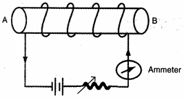
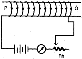
The figure shows a long solenoid,a cylindrical coil of a number of turns of insulated copper wire,connected to a battery through an ammeter $A$ and a rheostat $Rh$.
$(i)$ Which end of the solenoid is a $N$-pole and which end is a $S$-pole?
$(ii)$ Draw the magnetic field lines inside the solenoid and indicate their directions. Are magnetic field lines closed?
$(iii)$ How can you increase the strength of the magnetic field inside the solenoid? Give two methods.
$(i)$ Which end of the solenoid is a $N$-pole and which end is a $S$-pole?
$(ii)$ Draw the magnetic field lines inside the solenoid and indicate their directions. Are magnetic field lines closed?
$(iii)$ How can you increase the strength of the magnetic field inside the solenoid? Give two methods.
Solution
(N/A) $(i)$ Looking at end $P$,the current flows in a clockwise direction,therefore,$P$ acts as a south pole. Looking at end $Q$,the current appears to flow in an anti-clockwise direction,therefore,$Q$ acts as a north pole.
$(ii)$ Magnetic field lines inside a solenoid are shown in the figure. It is important to note that outside the solenoid,field lines are directed from the north pole to the south pole,but inside the solenoid,the field lines are directed from the south pole to the north pole. Yes,magnetic field lines are closed loops.
$(iii)$ The strength of the magnetic field inside a solenoid can be increased by:
$(a)$ Increasing the magnitude of the current flowing through the solenoid.
$(b)$ Increasing the number of turns of the copper wire in the solenoid.
0 likes
View Solution225
Medium
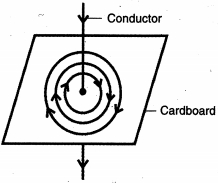
$A$ straight conductor passes vertically through a cardboard sprinkled with iron filings. Show the setting of iron filings when a weak current is passed in the downward direction and then the cardboard is gently tapped. Draw arrows to represent the direction of magnetic field lines.
What changes occur if,
$(i)$ the strength of current is increased?
$(ii)$ the single conductor is replaced by several parallel conductors each carrying same current flowing in the same direction?
What changes occur if,
$(i)$ the strength of current is increased?
$(ii)$ the single conductor is replaced by several parallel conductors each carrying same current flowing in the same direction?
Solution
(N/A) The image shows the pattern in which iron filings will set themselves. The arrows show the direction of magnetic field lines,which is clockwise for a downward current.
$(i)$ The arrangement of iron filings remains unchanged,but they get arranged up to a larger distance from the conductor when the strength of current is increased. This is because on increasing the strength of current,the strength of the magnetic field increases and it becomes effective up to a larger distance from the conductor.
$(ii)$ This increases the total magnetic field strength,as such the iron filings get arranged up to a larger distance from the conductors.
0 likes
View Solution226
Medium
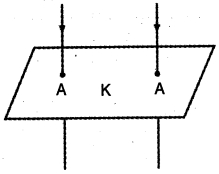
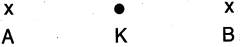
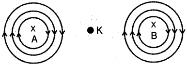
In the below figure,$A$ and $B$ represent two straight wires carrying equal currents in a direction at right angles to the plane of paper inwards. Sketch separately the magnetic field lines produced by each current. Give a reason why the magnetic field at $K$ (mid-point of the line joining $A$ and $B$) will be zero.
What will be the effect on the magnetic field at $K$ if the current in wire $B$ is reversed?
What will be the effect on the magnetic field at $K$ if the current in wire $B$ is reversed?
Solution
(N/A) The magnetic field lines produced by the current in wires $A$ and $B$ are concentric circles centered at the wires,with their direction determined by the Right-Hand Thumb Rule. Since both currents flow inwards,the field lines are clockwise.
Point $K$ is equidistant from wires $A$ and $B$. Since both wires carry equal currents,the magnetic fields produced at $K$ by wire $A$ and wire $B$ are equal in magnitude. According to the Right-Hand Thumb Rule,the magnetic field due to wire $A$ at $K$ points in one direction (e.g.,upwards),while the magnetic field due to wire $B$ at $K$ points in the opposite direction (e.g.,downwards). Because these two fields are equal in magnitude and opposite in direction,they cancel each other out,making the net magnetic field at point $K$ zero.
If the direction of current in wire $B$ is reversed (i.e.,it flows outwards),the direction of the magnetic field produced by wire $B$ at point $K$ also reverses. Consequently,both magnetic fields at point $K$ will now point in the same direction and add up,resulting in a non-zero net magnetic field.
0 likes
View Solution227
Medium
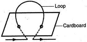
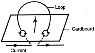
The figure below shows a current-carrying loop passing through a sheet of cardboard. Draw three magnetic field lines on the cardboard.
Give two factors on which the magnitude of the magnetic field at the centre of the loop depends.
Give two factors on which the magnitude of the magnetic field at the centre of the loop depends.
Solution
(N/A) The magnetic field lines around a current-carrying circular loop are concentric circles near the points where the wire passes through the cardboard. As we move towards the centre of the loop,the circles become larger and larger,and near the centre,the field lines appear as straight lines.
The magnitude of the magnetic field $(B)$ at the centre of a circular current-carrying loop depends on the following two factors:
$(i)$ The strength of the current $(I)$ flowing through the loop: The magnitude of the magnetic field is directly proportional to the current $(B \propto I)$.
$(ii)$ The radius of the loop $(r)$: The magnitude of the magnetic field is inversely proportional to the radius of the loop $(B \propto 1/r)$.
0 likes
View Solution228
Medium
$A$ student performs an experiment to study the magnetic effect of current around a current-carrying straight conductor. He reports that:
$(i)$ The direction of deflection of the north pole of a compass needle kept at a given point near the conductor remains unaffected even when the terminals of the battery sending current in the wire are interchanged.
$(ii)$ For a given battery,the degree of deflection of a $N$-pole decreases when the compass is kept at a point farther away from the conductor.
Which of the above observations of the student is incorrect and why?
Solution
(A) $(i)$ The first statement is incorrect because the direction of the magnetic field around the conductor is reversed when the direction of the current flowing in the conductor changes. Hence,the direction of deflection of the $N$-pole of the compass needle cannot remain unaffected when the terminals of the battery sending current in the wire or conductor are interchanged.
$(ii)$ The second statement is correct because the magnetic field strength decreases with an increase in the distance from the conductor.
$(ii)$ The second statement is correct because the magnetic field strength decreases with an increase in the distance from the conductor.
0 likes
View Solution229
EasyMCQ
$A$ current-carrying wire produces:
A
an electric field
B
a magnetic field
C
both electric and magnetic fields
D
neither electric nor magnetic field
Solution
(C) When a current flows through a wire,it creates a magnetic field around it,as demonstrated by Oersted's experiment. Additionally,because the wire contains charges (electrons) moving through it,there is also an electric field associated with the potential difference across the wire. Therefore,a current-carrying wire produces both electric and magnetic fields.
0 likes
View Solution230
MediumMCQ
By increasing the number of turns $3$ times in a toroidal solenoid,the magnetic field:
A
will remain unchanged
B
will become three times
C
will reduce to one-third
D
none of these
Solution
(B) The magnetic field $B$ inside a toroidal solenoid is given by the formula $B = \mu_0 n I$,where $n$ is the number of turns per unit length $(n = N / 2\pi r)$.
Substituting $n$,we get $B = \mu_0 (N / 2\pi r) I$.
Here,$N$ is the total number of turns,$I$ is the current,and $r$ is the radius of the toroid.
Since $B \propto N$,if the number of turns $N$ is increased by $3$ times,the magnetic field $B$ will also increase by $3$ times.
Substituting $n$,we get $B = \mu_0 (N / 2\pi r) I$.
Here,$N$ is the total number of turns,$I$ is the current,and $r$ is the radius of the toroid.
Since $B \propto N$,if the number of turns $N$ is increased by $3$ times,the magnetic field $B$ will also increase by $3$ times.
0 likes
View Solution231
EasyMCQ
The induced potential difference produced in a coil when a magnet is inserted into it does not depend upon:
A
Number of turns of the coil
B
The magnetic moment of the magnet
C
The resistance of the coil
D
The speed of approach of the magnet
Solution
(C) According to Faraday's law of electromagnetic induction,the induced electromotive force $(EMF)$ or potential difference is given by the formula: $e = -N \frac{d\phi}{dt}$.
Here,$N$ is the number of turns,and $\frac{d\phi}{dt}$ is the rate of change of magnetic flux.
$1$. The induced $EMF$ depends on the number of turns $(N)$.
$2$. The rate of change of flux $(\frac{d\phi}{dt})$ depends on the magnetic moment of the magnet (which determines the strength of the magnetic field) and the speed of approach of the magnet.
$3$. The resistance of the coil affects the induced current $(I = \frac{e}{R})$,but it does not affect the induced potential difference $(e)$ itself.
Therefore,the induced potential difference does not depend on the resistance of the coil.
0 likes
View Solution232
EasyMCQ
The laws of electromagnetism tell us that energy can be transferred from one object to another:
A
only in pulses but not continuously.
B
instantaneously
C
only if they are connected by a cable
D
even if there is no material medium
Solution
(D) According to the laws of electromagnetism,electromagnetic waves (such as light,radio waves,etc.) are capable of transferring energy through a vacuum. Unlike mechanical waves (like sound),which require a material medium to propagate,electromagnetic waves consist of oscillating electric and magnetic fields that sustain each other. Therefore,energy can be transferred from one object to another even in the absence of any material medium.
0 likes
View Solution233
EasyMCQ
$A$ soft iron bar is introduced inside a current-carrying solenoid. The magnetic field inside the solenoid:
A
will increase
B
will decrease
C
no change
D
uncertain
Solution
(A) When a soft iron bar is placed inside a current-carrying solenoid,it acts as a core.
Soft iron is a ferromagnetic material with high magnetic permeability.
When the solenoid is energized,the soft iron core gets strongly magnetized by the magnetic field of the solenoid.
The total magnetic field inside the solenoid becomes the sum of the magnetic field produced by the current in the solenoid and the magnetic field produced by the magnetized soft iron core.
Therefore,the overall magnetic field inside the solenoid increases significantly.
0 likes
View Solution234
EasyMCQ
Inside a current carrying solenoid,the magnetic field lines are:
A
circular and do not intersect
B
along the axis of the solenoid and parallel to each other
C
perpendicular to the axis of the solenoid
D
none of these
Solution
(B) solenoid is a long coil containing a large number of close turns of insulated copper wire.
When an electric current flows through the solenoid,it produces a magnetic field similar to that of a bar magnet.
Inside the solenoid,the magnetic field lines are in the form of parallel straight lines.
This indicates that the magnetic field is uniform at all points inside the solenoid and is directed along the axis of the solenoid.
0 likes
View Solution235
EasyMCQ
The material of the core of a strong electromagnet is:
A
steel
B
wrought iron
C
soft iron
D
brass
Solution
(C) An electromagnet is a type of magnet in which the magnetic field is produced by an electric current.
To create a strong electromagnet, the core material must have high magnetic permeability and low retentivity.
$soft \ iron$ is an ideal material for this purpose because it can be easily magnetized and demagnetized.
When the current is switched on, it becomes a strong magnet, and when the current is switched off, it loses its magnetism almost instantly.
Therefore, $soft \ iron$ is used for the core of a strong electromagnet.
0 likes
View Solution236
EasyMCQ
The direction of induced potential difference (induced current) is given by:
A
Cork screw rule
B
Right hand thumb rule
C
Fleming's left hand rule
D
Fleming's right hand rule
Solution
(D) The direction of the induced current in a conductor moving in a magnetic field is determined by Fleming's right-hand rule.
According to this rule,if you stretch the thumb,forefinger,and middle finger of your right hand such that they are mutually perpendicular to each other,then:
$1$. The thumb points in the direction of the motion of the conductor.
$2$. The forefinger points in the direction of the magnetic field.
$3$. The middle finger points in the direction of the induced current (or induced potential difference).
0 likes
View Solution237
EasyMCQ
The principle of which of these devices is based on electromagnetism?
A
Transformer
B
Motor
C
Galvanometer
D
All of these
Solution
(D) Electromagnetism is the physical phenomenon where an electric current produces a magnetic field.
$1$. $A$ transformer works on the principle of mutual induction,which is a direct application of electromagnetic induction.
$2$. An electric motor works on the principle that a current-carrying conductor placed in a magnetic field experiences a force (Lorentz force).
$3$. $A$ galvanometer works on the principle that a current-carrying coil placed in a magnetic field experiences a torque.
Since all these devices rely on the interaction between electricity and magnetism,they are all based on the principles of electromagnetism.
0 likes
View Solution238
EasyMCQ
The magnetic field around a current-carrying straight conductor is:
A
directly proportional to $r$
B
inversely proportional to $r$
C
directly proportional to $r^{2}$
D
inversely proportional to $r^{2}$
Solution
(B) According to the Biot-Savart Law,the magnetic field $B$ produced by a long straight current-carrying conductor at a distance $r$ from the conductor is given by the formula: $B = \frac{\mu_{0}I}{2\pi r}$.
From this expression,it is clear that the magnetic field $B$ is inversely proportional to the distance $r$ from the conductor $(B \propto 1/r)$.
From this expression,it is clear that the magnetic field $B$ is inversely proportional to the distance $r$ from the conductor $(B \propto 1/r)$.
0 likes
View Solution239
EasyMCQ
The strength of the magnetic field of a solenoid does not depend upon:
A
current through it
B
number of turns of the coil
C
area of the coil
D
core of the coil
Solution
(C) The magnetic field strength $(B)$ inside a long solenoid is given by the formula $B = \mu_0 n I$,where $\mu_0$ is the permeability of free space,$n$ is the number of turns per unit length,and $I$ is the current flowing through the solenoid.
If a core material is used,the field becomes $B = \mu n I$,where $\mu$ is the permeability of the core material.
From this formula,it is clear that the magnetic field depends on the current $(I)$,the number of turns per unit length $(n)$,and the nature of the core material $(\mu)$.
The magnetic field strength of an ideal long solenoid does not depend on the cross-sectional area of the coil.
0 likes
View Solution240
MediumMCQ
The phenomenon of electromagnetic induction is:
A
the process of charging a body
B
the process of generating a magnetic field due to current passing through a coil
C
the process of rotating a coil of an electric motor
D
producing induced current in a coil by relative motion between a magnet and a coil
Solution
(D) Electromagnetic induction is the phenomenon where an electromotive force $(EMF)$ or current is induced in a conductor due to a changing magnetic field.
This occurs when there is relative motion between a magnet and a coil,which changes the magnetic flux linked with the coil.
According to Faraday's laws of induction,this change in magnetic flux induces an electric current in the circuit.
Therefore,option $D$ is the correct definition of electromagnetic induction.
0 likes
View Solution241
EasyMCQ
$A$ device used for producing current is:
A
generator
B
voltmeter
C
ammeter
D
galvanometer
Solution
(A) An electric generator is a device that converts mechanical energy into electrical energy,thereby producing an electric current.
$A$ voltmeter is used to measure the potential difference between two points in an electric circuit.
$An$ ammeter is used to measure the magnitude of electric current flowing through a circuit.
$A$ galvanometer is an instrument used to detect and measure small amounts of electric current in a circuit.
0 likes
View Solution242
EasyMCQ
If the direction of current is reversed,the direction of magnetic field is also reversed.
A
True
B
False
Solution
(A) According to the Right-Hand Thumb Rule,the direction of the magnetic field produced by a current-carrying conductor depends on the direction of the current flow.
If the direction of the current is reversed,the orientation of the magnetic field lines also reverses,as predicted by the rule.
If the direction of the current is reversed,the orientation of the magnetic field lines also reverses,as predicted by the rule.
0 likes
View Solution243
EasyMCQ
To find the direction of the magnetic field around a current-carrying conductor,we use Fleming's left-hand rule.
A
True
B
False
Solution
(B) The statement is $False$.
Fleming's left-hand rule is used to determine the direction of the force acting on a current-carrying conductor placed in a magnetic field.
To find the direction of the magnetic field around a current-carrying conductor,we use the Right-Hand Thumb Rule (or Maxwell's Corkscrew Rule).
Fleming's left-hand rule is used to determine the direction of the force acting on a current-carrying conductor placed in a magnetic field.
To find the direction of the magnetic field around a current-carrying conductor,we use the Right-Hand Thumb Rule (or Maxwell's Corkscrew Rule).
0 likes
View Solution244
EasyMCQ
The magnetic field produced by a straight current-carrying conductor is in the form of concentric circles.
A
True
B
False
Solution
(A) According to the Right-Hand Thumb Rule,when a current flows through a straight conductor,the magnetic field lines generated around it are circular in shape.
These field lines are concentric,meaning they share the same center,which is the conductor itself.
As the distance from the conductor increases,the circles become larger and the magnetic field strength decreases.
These field lines are concentric,meaning they share the same center,which is the conductor itself.
As the distance from the conductor increases,the circles become larger and the magnetic field strength decreases.
0 likes
View Solution245
EasyMCQ
$A$ current-carrying solenoid behaves like a bar magnet.
A
True
B
False
Solution
(A) current-carrying solenoid produces a magnetic field pattern that is identical to that of a bar magnet.
One end of the solenoid acts as the North pole $(N)$,while the other end acts as the South pole $(S)$.
Therefore,it behaves exactly like a bar magnet.
One end of the solenoid acts as the North pole $(N)$,while the other end acts as the South pole $(S)$.
Therefore,it behaves exactly like a bar magnet.
0 likes
View Solution246
EasyMCQ
Inside a solenoid,the magnetic field is constant in magnitude and direction.
A
True
B
False
Solution
(A) The magnetic field inside a long solenoid carrying current is uniform,meaning it is constant in both magnitude and direction at all points within the solenoid. This is represented by parallel magnetic field lines.
0 likes
View Solution247
EasyMCQ
The magnetic field produced by a current-carrying solenoid depends directly upon the strength of the current.
A
True
B
False
Solution
(A) The magnetic field strength $(B)$ inside a current-carrying solenoid is given by the formula $B = \mu_0 n I$,where $\mu_0$ is the permeability of free space,$n$ is the number of turns per unit length,and $I$ is the current flowing through the solenoid.
Since $B \propto I$,the magnetic field is directly proportional to the strength of the current flowing through the solenoid.
Therefore,the statement is True.
Since $B \propto I$,the magnetic field is directly proportional to the strength of the current flowing through the solenoid.
Therefore,the statement is True.
0 likes
View Solution248
EasyMCQ
In order to find the force experienced by a current-carrying conductor,we can use Maxwell's corkscrew rule.
A
True
B
False
Solution
(B) The statement is $False$.
Maxwell's corkscrew rule (also known as the Right-Hand Grip Rule) is used to determine the direction of the magnetic field produced by a current-carrying conductor.
To find the force experienced by a current-carrying conductor placed in a magnetic field,we use Fleming's Left-Hand Rule.
Maxwell's corkscrew rule (also known as the Right-Hand Grip Rule) is used to determine the direction of the magnetic field produced by a current-carrying conductor.
To find the force experienced by a current-carrying conductor placed in a magnetic field,we use Fleming's Left-Hand Rule.
0 likes
View Solution249
EasyMCQ
Whenever the magnetic field through a coil is changed,a potential difference is produced in the coil.
A
True
B
False
Solution
(A) The statement is $True$. This phenomenon is known as electromagnetic induction. According to Faraday's law of electromagnetic induction,whenever the magnetic flux linked with a coil changes,an electromotive force $(EMF)$ or potential difference is induced in the coil. This induced $EMF$ causes a current to flow if the circuit is closed.
0 likes
View Solution250
EasyMCQ
The strength of the induced potential difference depends on the relative speed between the coil and the magnet.
A
True
B
False
Solution
(A) According to Faraday's law of electromagnetic induction,the magnitude of the induced electromotive force $(EMF)$ or potential difference in a coil is directly proportional to the rate of change of magnetic flux linked with the coil.
When a magnet moves relative to a coil,the magnetic flux changes.
The rate of change of magnetic flux depends on the relative speed between the magnet and the coil.
Therefore,a higher relative speed results in a faster change in magnetic flux,which induces a stronger potential difference.
When a magnet moves relative to a coil,the magnetic flux changes.
The rate of change of magnetic flux depends on the relative speed between the magnet and the coil.
Therefore,a higher relative speed results in a faster change in magnetic flux,which induces a stronger potential difference.
0 likes
View SolutionMagnetic Effects of Electric Current — Mix Examples - Magnetic Effects of Electric Current · Frequently Asked Questions
1Are these Magnetic Effects of Electric Current questions useful for JEE and NEET?
Yes. All questions in this section are mapped to JEE Main and NEET exam patterns. Previous year questions from JEE Main, NEET, GUJCET and state-level exams are included with full solutions.
2Can I switch to Hindi or Gujarati for these questions?
Yes. Use the language tabs in the hero section or the sidebar to view the same questions and solutions in English, Hindi or Gujarati.
3How do I generate a question paper from this subtopic?
Use the Vedclass Exam Paper Generator — select the chapter and subtopic, set difficulty, and generate Sets A, B, C, D automatically. First 3 chapters of every subject are free.
Vedclass Products
For Students
Vedclass Test Series
Mock tests in real JEE/NEET style with performance analysis. 5-day free trial.
Start Free TrialFor Teachers
Exam Paper Generator
Generate Set A/B/C/D papers from this chapter in 2 minutes. 3 chapters free.
Try FreeFor Institutes
Online Exam Module
Live online exams with unlimited students, 360° analytics & white-label branding.
See DemoFor Teachers & Institutes
Generate a Magnetic Effects of Electric Current Exam Paper in 2 Minutes
Select subtopic & difficulty — Sets A, B, C, D auto-generated with No Repeat logic.
First 3 chapters of every subject are free — no payment required.