
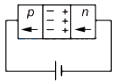
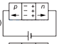
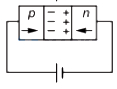
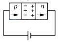
In the case of forward biasing of a $p-n$ junction diode,which one of the following figures correctly depicts the direction of conventional current (indicated by an arrow mark)?
- A
- B
- C
- D
Explore More
Similar Questions
The cut-in voltage for a silicon diode is approximately $V$.
Easy
View SolutionIf a diode having infinite reverse bias resistance is connected in a circuit as shown in the figure,then $I_1$ and $I_2$ are respectively:
The circuit shown contains a $12 \, V$ battery,a $4 \, \Omega$ resistor,and two branches in parallel,each containing an ideal diode and a resistor. Branch $1$ has diode $D_1$ and a $3 \, \Omega$ resistor,while branch $2$ has diode $D_2$ and a $2 \, \Omega$ resistor. Determine the current flowing through the circuit. (in $, A$)
Medium
View SolutionWhich of the following circuits is in forward bias?
Medium
View SolutionGiven below are two statements: one is labelled as Assertion $A$ and the other is labelled as Reason $R$.
Assertion $A$: $A$ diode under reverse-biased condition provides very small current which is nearly independent of voltage until a critical limit at which the current increases drastically.
Reason $R$: Below the critical voltage limit,only majority charge carriers flow which increases drastically above critical voltage.
Vedclass Products
For Students
Vedclass Test Series
Mock tests in real JEE/NEET style with performance analysis. 5-day free trial.
Start Free TrialFor Teachers
Exam Paper Generator
Generate Set A/B/C/D exam papers from 7.5L+ questions in 2 minutes. 3 chapters free.
Try FreeFor Institutes
Online Exam Module
Live online exams with unlimited students, 360° analytics & white-label branding.
See Demo