
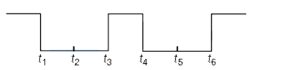
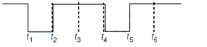
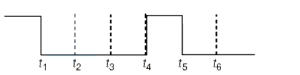
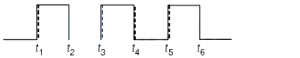
Consider the circuit given below. Choose the sketch depicting the output $Y$ of this circuit having inputs $A$ and $B$ as given below.
- A
- B
- C
- D
Explore More
Similar Questions
Input waveforms $A$ and $B$ as shown in Fig-$I$ are applied to the combination of gates as shown in Fig-$II$. Which of the waveforms shown in Fig-$(i)$ to Fig-$(iv)$ correctly represents the output waveform $Y$?
Difficult
View SolutionThe symbolic representations of four logic gates are given below. The logic symbols for $OR$,$NOT$,and $NAND$ gates are respectively:
MediumAIPMT 2009
View SolutionThe given figure shows the waveforms for two inputs $A$ and $B$ and that for the output $Y$ of a logic circuit. The logic circuit is
Medium
View SolutionThe logic gate equivalent to the combination of logic gates shown in the figure is
The new switching circuit for the following circuit by simplifying the given circuit is
Vedclass Products
For Students
Vedclass Test Series
Mock tests in real JEE/NEET style with performance analysis. 5-day free trial.
Start Free TrialFor Teachers
Exam Paper Generator
Generate Set A/B/C/D exam papers from 7.5L+ questions in 2 minutes. 3 chapters free.
Try FreeFor Institutes
Online Exam Module
Live online exams with unlimited students, 360° analytics & white-label branding.
See Demo