
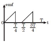
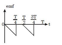
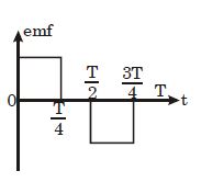
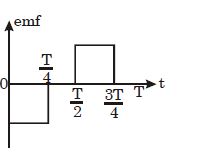
The current $i$ in a coil varies with time as shown in the figure. The variation of induced $emf$ with time would be:
- A
- B
- C
- D
Explore More
Similar Questions
The switches in figures $(a)$ and $(b)$ are closed at $t = 0$.
Medium
View SolutionThe figure shows a circuit that contains three identical resistors with resistance $R = 9.0 \,\Omega$ each,two identical inductors with inductance $L = 2.0 \,mH$ each,a capacitor $C$,and an ideal battery with $emf \,\varepsilon = 18 \,V$. The current $i$ through the battery just after the switch is closed is:
MediumNEET 2017
View SolutionDiscuss the types of $AC$ generator. How much power they deliver? What is the frequency of $AC$ generator?
Medium
View Solution$A$ special metal $S$ conducts electricity without any resistance. $A$ closed wire loop,made of $S$,does not allow any change in flux through itself by inducing a suitable current to generate a compensating flux. The induced current in the loop cannot decay due to its zero resistance. This current gives rise to a magnetic moment which in turn repels the source of magnetic field or flux. Consider such a loop,of radius $a$,with its center at the origin. $A$ magnetic dipole of moment $m$ is brought along the axis of this loop from infinity to a point at distance $r \gg a$ from the center of the loop with its north pole always facing the loop,as shown in the figure.
The magnitude of the magnetic field of a dipole $m$,at a point on its axis at distance $r$,is $\frac{\mu_0}{2 \pi} \frac{m}{r^3}$,where $\mu_0$ is the permeability of free space. The magnitude of the force between two magnetic dipoles with moments $m_1$ and $m_2$,separated by a distance $r$ on the common axis,with their north poles facing each other,is $\frac{k m_1 m_2}{r^4}$,where $k$ is a constant of appropriate dimensions. The direction of this force is along the line joining the two dipoles.
$(1)$ When the dipole $m$ is placed at a distance $r$ from the center of the loop (as shown in the figure),the current induced in the loop will be proportional to
$(A) \frac{m}{r^3} \quad (B) \frac{m^2}{r^2} \quad (C) \frac{m}{r^2} \quad (D) \frac{m^2}{r}$
$(2)$ The work done in bringing the dipole from infinity to a distance $r$ from the center of the loop by the given process is proportional to
$(A) \frac{m}{r^5} \quad (B) \frac{m^2}{r^5} \quad (C) \frac{m^2}{r^6} \quad (D) \frac{m^2}{r^7}$
The switch $S$ of the circuit shown in the figure is closed at $t = 0$. If $e$ denotes the induced emf in the inductor $L$ and $i$ denotes the current flowing through the circuit at time $t$,which of the following graphs correctly represents the variation of $e$ with time $t$?
Medium
View SolutionVedclass Products
For Students
Vedclass Test Series
Mock tests in real JEE/NEET style with performance analysis. 5-day free trial.
Start Free TrialFor Teachers
Exam Paper Generator
Generate Set A/B/C/D exam papers from 7.5L+ questions in 2 minutes. 3 chapters free.
Try FreeFor Institutes
Online Exam Module
Live online exams with unlimited students, 360° analytics & white-label branding.
See Demo