
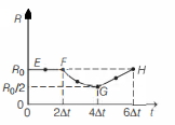
In the circuit shown below,the resistance and the emf source are both variable. The graph of seven readings of the voltmeter and the ammeter ($V$ and $I$,respectively) for different settings of resistance and the emf,taken at equal intervals of time $\Delta t$,are shown below by the dots connected by the curve $EFGH$. Consider the internal resistance of the battery to be negligible and the voltmeter and ammeter to be ideal devices. (Take $R_0 = \frac{V_0}{I_0}$). Then,the plot of the resistance as a function of time corresponding to the curve $EFGH$ is given by:
- A
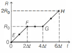
- B
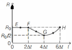
- C
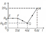
- D
Explore More
Similar Questions
In the circuit shown in the figure,the capacitor $C$ is initially uncharged and the key $K$ is open. In this condition,a current of $1 \,A$ flows through the $1 \,\Omega$ resistor. The key is closed at time $t=t_0$. Which of the following statement(s) is(are) correct?
[Given: $e^{-1}=0.36$]
$(A)$ The value of the resistance $R$ is $3 \,\Omega$.
$(B)$ The current through the $3 \,\Omega$ resistor (connected in parallel to the $1 \,\Omega$ and $R$ branches) is $2 \,A$ when $K$ is open.
$(C)$ At $t=t_0+7.2 \,\mu s$,the current in the capacitor branch is $0.6 \,A$.
$(D)$ For $t < \infty$,the charge on the capacitor is $12 \,\mu C$.
MediumIIT 2023
View SolutionSix similar bulbs are connected as shown in the figure with a $DC$ source of $emf\; E$,and zero internal resistance. The ratio of power consumption by the bulbs when $(i)$ all are glowing and $(ii)$ in the situation when two from section $A$ and one from section $B$ are glowing,will be
DifficultNEET 2019
View SolutionIn Circuit-$1$ and Circuit-$2$ shown in the figures,$R_1=1 \Omega, R_2=2 \Omega$ and $R_3=3 \Omega$. $P_1$ and $P_2$ are the power dissipations in Circuit-$1$ and Circuit-$2$ when the switches $S_1$ and $S_2$ are in open conditions,respectively. $Q_1$ and $Q_2$ are the power dissipations in Circuit-$1$ and Circuit-$2$ when the switches $S_1$ and $S_2$ are in closed conditions,respectively. Which of the following statement$(s)$ is(are) correct?
$(A)$ When a voltage source of $6 V$ is connected across $A$ and $B$ in both circuits,$P_2 > P_1$.
$(B)$ When a constant current source of $2 A$ is connected across $A$ and $B$ in both circuits,$P_1 > P_2$.
$(C)$ When a voltage source of $6 V$ is connected across $A$ and $B$ in Circuit-$1$,$Q_1 > P_1$.
$(D)$ When a constant current source of $2 A$ is connected across $A$ and $B$ in both circuits,$Q_1 > Q_2$.
The temperature of the cold junction of a thermocouple is $0\,^oC$ and the temperature of the hot junction is $T\,^oC$. The thermo e.m.f. is given by the relation $E = AT - \frac{1}{2}BT^2$ (where $A = 16$ and $B = 0.08$). The temperature of inversion is ............... $^oC$.
DifficultAIIMS 2001
View SolutionFor a thermocouple,the neutral temperature is $270^{\circ}C$ when its cold junction is at $20^{\circ}C$. What will be the neutral temperature and the temperature of inversion when the temperature of the cold junction is increased to $40^{\circ}C$?
Medium
View SolutionVedclass Products
For Students
Vedclass Test Series
Mock tests in real JEE/NEET style with performance analysis. 5-day free trial.
Start Free TrialFor Teachers
Exam Paper Generator
Generate Set A/B/C/D exam papers from 7.5L+ questions in 2 minutes. 3 chapters free.
Try FreeFor Institutes
Online Exam Module
Live online exams with unlimited students, 360° analytics & white-label branding.
See Demo