
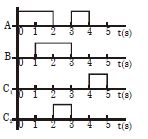
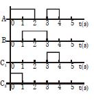
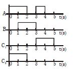
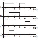
Draw the output signals $C_1$ and $C_2$ for the given combination of logic gates. (Up to $5 \ s$)
- A
- B
- C
- D
Explore More
Similar Questions
The $NOR$ gate is a combination of which two gates?
Easy
View SolutionIn the circuit shown, inputs $A$ and $B$ are in states $1$ and $0$ respectively. What is the only possible stable state of the outputs $X$ and $Y$?
The logic gate combination circuit shown in the figure performs the logic function of
Four $NOR$ gates are connected as shown in the figure. The truth table for the given figure is:
DifficultJEE MAIN 2021
View SolutionIn the circuit below,$A$ and $B$ represent two inputs and $C$ represents the output. The circuit represents:
Medium
View SolutionVedclass Products
For Students
Vedclass Test Series
Mock tests in real JEE/NEET style with performance analysis. 5-day free trial.
Start Free TrialFor Teachers
Exam Paper Generator
Generate Set A/B/C/D exam papers from 7.5L+ questions in 2 minutes. 3 chapters free.
Try FreeFor Institutes
Online Exam Module
Live online exams with unlimited students, 360° analytics & white-label branding.
See Demo